Language selection

Search

Patent 2298989 Summary

Third-party information liability

Some of the information on this Web page has been provided by external sources. The Government of Canada is not responsible for the accuracy, reliability or currency of the information supplied by external sources. Users wishing to rely upon this information should consult directly with the source of the information. Content provided by external sources is not subject to official languages, privacy and accessibility requirements.

Claims and Abstract availability

Any discrepancies in the text and image of the Claims and Abstract are due to differing posting times. Text of the Claims and Abstract are posted:

  • At the time the application is open to public inspection;
  • At the time of issue of the patent (grant).
(12) Patent: (11) CA 2298989
(54) English Title: PRODUCT SENSORS FOR AIR SEEDER
(54) French Title: CAPTEURS DE PRODUITS POUR SEMOIR PNEUMATIQUE
Status: Deemed expired
Bibliographic Data
(51) International Patent Classification (IPC):
  • A01C 7/20 (2006.01)
  • A01C 7/04 (2006.01)
  • A01C 7/10 (2006.01)
  • A01C 7/12 (2006.01)
  • G01F 1/05 (2006.01)
(72) Inventors :
  • GREGOR, DAVID WALTER (United States of America)
  • DETRICK, STEVE BLAINE (United States of America)
(73) Owners :
  • DEERE & COMPANY (United States of America)
(71) Applicants :
  • DEERE & COMPANY (United States of America)
(74) Agent: BORDEN LADNER GERVAIS LLP
(74) Associate agent:
(45) Issued: 2003-11-18
(22) Filed Date: 2000-02-18
(41) Open to Public Inspection: 2000-12-28
Examination requested: 2000-02-18
Availability of licence: N/A
(25) Language of filing: English

Patent Cooperation Treaty (PCT): No

(30) Application Priority Data:
Application No. Country/Territory Date
09/340,968 United States of America 1999-06-28

Abstracts

English Abstract

The product meter of an air seeder is vertically positioned between a product tank and a primary air distribution manifold. The product meter is provided with an inlet passage and an outlet passage. Product from the product tank is received in the inlet passage where it is directed to the metering chamber. A meter roller is located in the metering chamber for metering the product received from the product tank. After the product has been metered it is transported though the outlet passage to the primary distribution manifold. Optical product sensors may be located in either the inlet passage or the outlet passage to detect the operation of the product meter.


French Abstract

Le doseur de produit d'un semoir pneumatique est positionné verticalement entre un réservoir de produit et un collecteur de distribution d'air principal. Le doseur de produit est doté d'un passage d'entrée et d'un passage de sortie. Le produit provenant du réservoir de produit est reçu dans le passage d'entrée où il est dirigé vers la chambre de dosage. Un rouleau doseur est situé dans la chambre de dosage pour mesurer le produit reçu à partir du réservoir de produit. Une fois qu'un produit a été dosé, il est transporté à travers le passage de sortie vers le collecteur de distribution principal. Des capteurs de produit optiques peuvent être situés dans le passage d'entrée ou le passage de sortie pour détecter le fonctionnement du doseur de produit.

Claims

Note: Claims are shown in the official language in which they were submitted.


The embodiments of the invention in which an exclusive property or privilege
is
claimed are defined as follows:

1. A seed cart for an air seeder, the seed cart comprising:
a frame;
rotatable wheels mounted to the frame;
a product tank mounted to the frame for holding a granular product;
a product meter associated with the product tank for metering the product, the
product meter having an outlet passage;
a primary air distribution manifold located below the product meter for
receiving
metered product from the outlet passage of the product meter, the primary air
distribution
manifold having a venturi;
a blower mounted to the frame for directing an air stream through the venturi
for
transporting the metered product received from the product meter; and
a sensor mounted in the outlet passage for sensing the passage of metered
product
through the outlet passage as the metered product passes from the product
meter to the
primary air distribution manifold.

2. A seed cart as defined by claim 1 wherein the sensor is an optical sensor.

3. A seed cart as defined by claim 2 wherein the product tank is pressurized
by the
blower.

4. A seed cart as defined by claim 3 wherein the product meter comprises an
inlet
passage for receiving product from the product tank, a metering chamber
positioned
between the inlet passage and the outlet passage and a fluted metering roller
rotatively
positioned in the metering chamber.

5. A product meter for an air seeder, the product meter comprising:
a metering chamber having an inlet passage for receiving product and an outlet
passage for dispensing metered product;
a rotatable meter roller located in the metering chamber; and
a sensor mounted in the outlet passage for sensing the passage of metered
product
out of the metering chamber.

6. A product meter as defined by claim 5 wherein the sensor is an optical
sensor.

Description

Note: Descriptions are shown in the official language in which they were submitted.


CA 02298989 2000-02-18
PRODUCT SENSORS FOR AIR SEEDER
Background of the Invention
1. Field of the Invention:
The present invention is directed to improved optical sensor locations in the
product
meter of an air seeder.
2. Description of the Prior Art:
Air seeders are commonly towed by tractors to apply seed and/or fertilizer to
a field.
As an example, an air seeder may be towed in combination with a tilling
implement, one
behind the other, to place seed and fertilizer under the surface of the soil.
An air seeder has
as its central component a wheeled seed cart which comprises one or more frame-
mounted
product tanks for holding granular product, such as seed and/or fertilizer.
Air seeders are
also provided with product meters associated with each product tank for
dispensing metered
product from the respective product tank into a pneumatic distribution system
for delivering
the metered product to the field.
Typically, air seeders are provided with volumetric meters which measure a
fixed
volume of granular product per unit of linear distance. These volumetric
meters typically
comprise either augers or fluted cylinders (meter rollers). The product meters
rotate to feed
metered product into a pneumatic distribution system. The pneumatic
distribution system of
an air seeder generally utilizes a blower to provide at least one airstream
which flows
through the pneumatic distribution system to seed boots where product is
deposited in the
soil. Metered product is introduced into the air stream at a primary air
distribution manifold
located below the product meter. Product is carried by the air stream through
distribution
lines to a series of secondary distribution manifolds ("headers"), which in
turn distribute
product through individual lines to seed boots mounted behind ground openers
on the tilling
implement.
Current air seeders do not provide a method of sensing product flow in the
meter.
For positive pressure air systems, the product tank of the air seeder must be
pressurized to
meter product correctly. When pressure is lost in the tank, the flow of
metered product
would be slowed or even stop. Current sensors sense product flow downstream
from the
manifolds. In applications where two products from two separate tanks are
metered into a
single rank of tubes at different locations, the product flow from individual
meters cannot be
sensed because of the product meters being connected to the same air lines.
One meter
can stop metering while others continue to function properly thus giving no
warning to the
operator that the flow of one product has stopped or slowed because of the
continual flow of
product from the other meters.

CA 02298989 2000-02-18
Summary
It is an object of the present invention to provide improved air seeder sensor
by
locating the sensors in the product meter itself.
It is a feature of the present invention that optical product sensors are
located in
either the inlet or outlet passage of the product meter.
The product meter of an air seeder is vertically positioned between a product
tank
and a primary air distribution manifold. The product meter is provided with an
inlet passage
and an outlet passage. Product from the product tank is received in the inlet
passage where
it is directed to the metering chamber. A meter roller is located in the
metering chamber for
metering the product received from the product tank. After the product has
been metered it
is transported though the outlet passage to the primary distribution manifold.
Optical product
sensors may be located in either the inlet passage or the outlet passage to
detect the
operation of the product meter.
BRIEF DESCRIPTION OF THE DRAWINGS
Figure 1 is a side view of an air seeder.
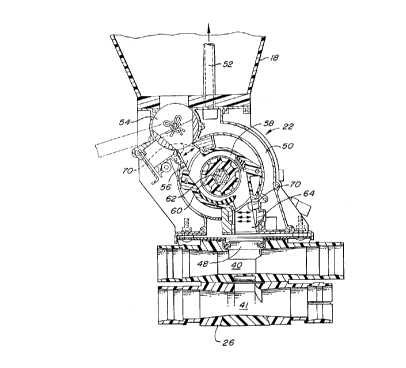
Figure 2 is a cross sectional view of the product meter and the primary
distribution
manifold.
DETAILED DESCRIPTION
As shown in Figure 1, air seeder 10 comprises a seed cart 12 and a tilling
implement
14. The seed cart 12 is typically towed by a tractor through a field to be
seeded. The seed
cart 12 has a frame 16 supporting a first product tank 18 and a second product
tank 19.
Wheels 20 are rotatably mounted to the frame. Both product tanks 18 and 19 are
provided
with identical product meters 22 and primary air distribution manifolds 26.
Only the product
meter and primary distribution manifold associated with product tank 18 is
illustrated. Both
product meters 22 are located below the product tanks 18 and 19 and receive
product
therefrom for controlled feeding of product into a pneumatic distribution
system 24. The
primary air distribution manifolds 26 are located below the product meters 22.
Both
manifolds are part of the pneumatic distribution system 24. Figure 1
illustrates a double shot
air seeder wherein a first product contained in product tank 18 is directed to
the top rank
portion of the air stream and the second product contained in product tank 19
is directed to
the bottom rank portion of the air stream. The tilling implement 14 is towed
behind the seed
cart 12 and comprises a frame 28 to which ground openers 30 are mounted. The
tilling
implement may be provided with seed row finishing equipment such as packers 32
The pneumatic distribution system 24 distributes metered product from the
product
2

CA 02298989 2000-02-18
tanks 18 and 19 to the ground openers 30. The product contained in the product
tanks 18
and 19 may include seed, fertilizer or other granular products. The pneumatic
distribution
system 24 comprises a blower 34 driven by a hydraulic motor which directs a
stream of
pressurized air through an adjustable damper 36. The damper 36 in turn directs
the
modified air stream to a top rank of tubes 38 and to a bottom rank of tubes
39. Typically
both ranks of tubes would include multiple tubes for receiving metered
product. The top rank
of tubes 38 directs the top rank portion of the air stream into the top rank
of venturis 40 in
the primary air distribution manifolds 26 associated with both product tanks.
Similarly, the
bottom rank of tubes 39 directs the bottom rank portion of the air stream into
a bottom rank
of venturis 41 in the primary distribution manifolds 26.
Each of the top rank tubes 38 that extend rearwardly from the primary
distribution
manifold associated with product tank 19 proceeds to an individual secondary
air distribution
manifold 44. Each of the secondary air distribution manifolds have individual
tubes 46
which extend to the ground openers 30. Similarly each of the bottom rank of
tubes 39
extend from the primary air distribution manifold 22 associated with the
product tank 19 to an
individual secondary air distribution manifold 44. The secondary air
distribution manifolds 44
are identical and comprise an upwardly extending tube having a header which
distributes the
product contained in the air stream to the individual ground openers 30
through individual
tubes 46.
Product from tanks 18 and 19 is metered by the respective product meter 22.
The
product enters the air stream through the venturis 40 or 41. The primary air
distribution
manifolds 26 are provided with a first selector valve 48 positioned between
the first product
meter 22 and the venturis 40 and 41 for selectively directing metered product
to either the
top rank venturi 40 or the bottom rank venturi 41. For example, product in
tank 18 may be
directed to the top rank air stream, and product in tank 19 maybe directed to
the bottom rank
air stream as dictated by the position of selector valve 48,
Pressurized air from the air stream is used to pressurize the product tanks.
More
specifically, a portion of the air stream is directed through passage 50 in
the product meter
and into tube 52 for pressurizing tank 18.
Product in tank 18 is directed past shutoff valve 54 through inlet passage 56
into
metering chamber 58 having a fluted metering roller 60 which is rotatively
driven by hex
shaft 62. The metered product is directed through outlet passage 64 to one of
the venturis
or 41 depending upon the position of the selector valve 48.
Optical sensors 70 maybe located in inlet passage 56 or outlet passage 64 for
3

CA 02298989 2002-11-08
sensing the passage of product through these passages. Outlet 64 is the more
desirable
location as a sensor located in this passage directly senses product flow from
the product
meter to the pneumatic distribution system 24. The optical sensors 70 may be
of the type
disclosed in US Patents 5,650,609 and 5,847,389.
The invention should not be limited to the above described embodiment, but
should
be limited solely to the claims that follow:
4

Representative Drawing
A single figure which represents the drawing illustrating the invention.
Administrative Status

For a clearer understanding of the status of the application/patent presented on this page, the site Disclaimer , as well as the definitions for Patent , Administrative Status , Maintenance Fee  and Payment History  should be consulted.

Administrative Status

Title Date
Forecasted Issue Date 2003-11-18
(22) Filed 2000-02-18
Examination Requested 2000-02-18
(41) Open to Public Inspection 2000-12-28
(45) Issued 2003-11-18
Deemed Expired 2019-02-18

Abandonment History

There is no abandonment history.

Payment History

Fee Type Anniversary Year Due Date Amount Paid Paid Date
Request for Examination $400.00 2000-02-18
Registration of a document - section 124 $100.00 2000-02-18
Application Fee $300.00 2000-02-18
Maintenance Fee - Application - New Act 2 2002-02-18 $100.00 2002-02-15
Maintenance Fee - Application - New Act 3 2003-02-18 $100.00 2003-02-17
Final Fee $300.00 2003-08-29
Maintenance Fee - Patent - New Act 4 2004-02-18 $100.00 2004-02-03
Maintenance Fee - Patent - New Act 5 2005-02-18 $200.00 2005-02-02
Maintenance Fee - Patent - New Act 6 2006-02-20 $200.00 2006-01-30
Maintenance Fee - Patent - New Act 7 2007-02-19 $200.00 2007-01-30
Maintenance Fee - Patent - New Act 8 2008-02-18 $200.00 2008-01-30
Maintenance Fee - Patent - New Act 9 2009-02-18 $200.00 2009-01-30
Maintenance Fee - Patent - New Act 10 2010-02-18 $250.00 2010-02-02
Maintenance Fee - Patent - New Act 11 2011-02-18 $250.00 2011-01-31
Maintenance Fee - Patent - New Act 12 2012-02-20 $250.00 2012-01-30
Maintenance Fee - Patent - New Act 13 2013-02-18 $250.00 2013-01-30
Maintenance Fee - Patent - New Act 14 2014-02-18 $250.00 2014-02-17
Maintenance Fee - Patent - New Act 15 2015-02-18 $450.00 2015-02-16
Maintenance Fee - Patent - New Act 16 2016-02-18 $450.00 2016-02-15
Maintenance Fee - Patent - New Act 17 2017-02-20 $450.00 2017-02-13
Owners on Record

Note: Records showing the ownership history in alphabetical order.

Current Owners on Record
DEERE & COMPANY
Past Owners on Record
DETRICK, STEVE BLAINE
GREGOR, DAVID WALTER
Past Owners that do not appear in the "Owners on Record" listing will appear in other documentation within the application.
Documents

To view selected files, please enter reCAPTCHA code :


To view images, click a link in the Document Description column. To download the documents, select one or more checkboxes in the first column and then click the "Download Selected in PDF format (Zip Archive)" or the "Download Selected as Single PDF" button.

List of published and non-published patent-specific documents on the CPD .

If you have any difficulty accessing content, you can call the Client Service Centre at 1-866-997-1936 or send them an e-mail at CIPO Client Service Centre.


Document
Description 
Date
(yyyy-mm-dd) 
Number of pages   Size of Image (KB) 
Cover Page 2000-12-15 1 44
Abstract 2000-02-18 1 16
Representative Drawing 2000-12-15 1 18
Claims 2002-11-08 1 42
Description 2002-11-08 4 189
Cover Page 2003-10-15 1 46
Description 2000-02-18 4 190
Claims 2000-02-18 2 83
Drawings 2000-02-18 2 72
Assignment 2000-02-18 4 154
Prosecution-Amendment 2002-05-31 1 28
Prosecution-Amendment 2002-11-08 4 105
Correspondence 2003-08-29 1 24