Language selection

Search

Patent 2299107 Summary

Third-party information liability

Some of the information on this Web page has been provided by external sources. The Government of Canada is not responsible for the accuracy, reliability or currency of the information supplied by external sources. Users wishing to rely upon this information should consult directly with the source of the information. Content provided by external sources is not subject to official languages, privacy and accessibility requirements.

Claims and Abstract availability

Any discrepancies in the text and image of the Claims and Abstract are due to differing posting times. Text of the Claims and Abstract are posted:

  • At the time the application is open to public inspection;
  • At the time of issue of the patent (grant).
(12) Patent: (11) CA 2299107
(54) English Title: TUBULAR CORE ASSEMBLIES FOR ROLLS OF PAPER OR OTHER SHEET MATERIAL
(54) French Title: TUBES-SUPPORTS POUR ROULEAUX DE PAPIER OU AUTRES MATERIAUX EN FEUILLES
Status: Deemed expired
Bibliographic Data
(51) International Patent Classification (IPC):
  • B65H 75/30 (2006.01)
  • B65H 75/10 (2006.01)
  • B65H 75/18 (2006.01)
(72) Inventors :
  • KEWIN, DANIEL D. (Canada)
(73) Owners :
  • KEWIN, DANIEL D. (Canada)
(71) Applicants :
  • KEWIN, DANIEL D. (Canada)
(74) Agent: NA
(74) Associate agent: NA
(45) Issued: 2007-01-09
(22) Filed Date: 2000-02-22
(41) Open to Public Inspection: 2000-08-23
Examination requested: 2005-02-08
Availability of licence: N/A
(25) Language of filing: English

Patent Cooperation Treaty (PCT): No

(30) Application Priority Data:
Application No. Country/Territory Date
09/255,276 United States of America 1999-02-23

Abstracts

English Abstract

A tubular core assembly for roll of paper or other sheet material has a hollow cylindrical core member formed of paperboard material and an annular end member of plastic material within each opposite end portion of the core member. Each end member has an outer annular surface secured to the inner annular surface of the core member and an inner surface shaped to receive a roll supporting chuck. Each end member also has at least two radially-projecting lugs at the respective end of the tubular core assembly positioned so as to be rotationally balanced. The core member has at least two lug-receiving notches at each end receiving lugs of the respective end member to rotationally equalize continuous torque and axial chuck pressure from each end member to the core member. Each end member also has an inner annular surface at the end which is continuous and of constant radius around the circumference thereof.


French Abstract

Un ensemble à noyau tubulaire pour un rouleau de papier ou d'autre matériau en feuilles comprend un noyau cylindrique creux en carton et un élément annulaire d'extrémité fait de plastique dans chaque extrémité opposée de l'élément à noyau. Chaque élément d'extrémité est pourvu d'une surface annulaire extérieure fixée à la surface annulaire intérieure de l'élément à noyau et une surface intérieure dont la forme est prévue pour loger un mandrin de support du rouleau de papier. Chaque élément terminal est également pourvu d'au moins deux ergots saillant radialement à l'extrémité respective de l'ensemble à noyau qui sont positionnés de manière à assurer l'équilibre en rotation. L'élément noyau possède au moins deux encoches à chaque extrémité afin de recevoir les ergots de l'élément d'extrémité respectif, pour répartir également en rotation le couple continu et la pression axiale du mandrin de chaque élément d'extrémité appliqués à l'élément noyau. Chaque élément d'extrémité possède également une surface annulaire intérieure à l'extrémité qui est continue et dont le rayon est constant autour de la circonférence.

Claims

Note: Claims are shown in the official language in which they were submitted.


CLAIMS:
1. A tubular core assembly for roll of paper or other sheet material having:
a hollow cylindrical core member formed of paperboard material, and an annular
end member of plastic material within each opposite end portion of the core
member, each end member having an outer annular surface secured to the inner
annular surface of the core member and an inner surface shaped to receive a
roll
supporting chuck,
each end member having at least two radially-projecting lugs at the respective
end of the tubular core assembly positioned so as to be rotationally balanced,
said
core member having at least two lug-receiving notches at each end receiving
said lugs
of the respective end member to rotationally equalize continuous torque and
axial
chuck pressure from each end member to the core member, and
each end member having an inner annular surface at said end which is
continuous and of constant radius around the circumference thereof.
2. A tubular core assembly according to claim 1 wherein the annular end
member has two diametrically opposite radially-projecting lugs and the core
member
has two diametrically opposite lug-receiving notches.
3. A tubular core assembly according to claim 1 wherein each annular end
member has three radially-projecting lugs at 120° intervals around the
end member
and the core member has three similarly positioned lug-receiving notches.
4. A tubular core assembly according to claim 1 wherein each annular member
-7-


has four radially-projecting lugs at 90° intervals around the end
member and the core
has 4 similarly positioned lug-receiving notches.
5. A tubular core assembly according to claim 1 wherein each end member has
an internal diameter in the range of from about 3 to about 6 inches, an outer
diameter in the range of from about 3.25 to about 7 inches and a length in the
range
of from about 1.5 to about 6 inches, and each lug is solid and has a height
above the
outer annular surface of the end member in the range of from about 0.2 to
about 1
inch, a circumferential width in the range of from about 0.25 to about 3
inches, and
an axial length in the range of from about 0.5 to about 4 inches.
6. An annular end member of plastic material for insertion into an end portion
of a hollow cylindrical core member of a tubular core assembly for roll of
paper or
other sheet material, said end member having an outer annular surface
securable to
an inner annular surface of a core member and an inner annular surface shaped
to
receive a roll supporting chuck, at least two radially-projecting lugs
adjacent an end
thereof positioned so as to be rotatably balanced and engageable in lug-
receiving
notches in a core member, and an inner annular surface at said end which is
continuous and of constant radius around the circumference thereof.
7. An annular end member according to claim 6 having two diametrically
opposite radially-projecting lugs.
8. An annular end member according to claim 6 having three radially-projecting
-8-


lugs at 120° intervals.
9. An annular end member according to claim 6 having four radially-projecting
lugs at 90° intervals.
10. An annular end member according to claim 6 having an internal diameter in
the range of from about 3 to about 6 inches, an outer diameter in the range of
from
about 3.25 to about 7 inches and a length in the range of from about 1.5 to
about
6 inches, each lug being solid and having a height above the outer annular
surface
in the range of from about 0.2 to about 1 inch, a circumferential width in the
range
of from about 0.25 to about 3 inches, and an axial length in the range of from
about
0.5 to about 4 inches.
-9-

Description

Note: Descriptions are shown in the official language in which they were submitted.


CA 02299107 2006-O1-24
TUBULAR CORE ASSEMBLIES FOR ROLLS OF PAPER
OR OTHER SHEET MATERIAL
This invention relates to tubular core assemblies for rolls of paper or
other sheet material.
BACKGROUND OF THE INVENTION
Tubular core assemblies which have a hollow cylindrical core member of paper
board material and an annular end member of plastic material within each
opposite end portion of the core member are known, see for example U.S.
Patent No. 5,236,141 issued August 17, 1993, U.S. Patent No. 5,595,356 issued
January 21, 1997, U.S. Patent No. 5,615,845 issued April 1, 1997, U.S. Patent
No. 5,725,178 issued March 10, 1998 and U.S. Patent No. 5,829,713 issued
November 3, 1998.
U.S. Patent No. 5,615,845 and U.S. Patent No. 5,829,713 mentioned above are
particularly concerned with tubular core assemblies intended for mounting on
chucks having radially movable portions which are movable radially outwardly
to engage the inner surface of a tubular core assembly and on chucks which are
movable under axial pressure into engag:,ment witlf the ends of the tubular
core
assembly. Some of the tubular core assemblies described in these two prior
patents are also suitable for use with chucks having a single key which
engages
in a notch in the tubular core assembly.
In the printing industry, paper rolls have until recently usually been mounted
on
chucks by means of equipment which is manually controlled. However,
equipment which automatically mounts paper rolls on chucks without requiring
manual control is now being provided in press rooms. When such automated


CA 02299107 2000-02-22
equipment is used, chucks without keys are moved under axial pressure into
engagement with the ends of a tubular core assembly, because it is difficult
to mount
a paper roll on chucks with keys with such automated equipment.
For various reasons, it is advantageous to use with such automated equipment
tubular core assemblies which comprise a hollow cylindrical core member of
paperboard material with an annular end member of plastic material within each
opposite end portion thereof. As described in the previously mentioned prior
patents, each annular end member is provided with at least one radially-
projecting
lug adjacent an end thereof which is engaged in a lug-receiving notch in the
core
member to facilitate transmission of torque and axial chuck pressure from the
end
member to the core member. The prior patents also teach that each annular end
member should preferably be provided with a pair of notches at diametrically
opposite positions for receiving a key of a roll supporting chuck.
When automated equipment is used to mount paper rolls on axially movable
chucks without keys in a press room, it has been found to be necessary for the
chucks to engage the ends of the tubular core assemblies with very high
continuous
axial or radial pressure for efficiently transmitting torque thereto,
especially when
very heavy paper rolls are used, for example paper rolls having a weight when
fully
wound of about 3,000 lbs. or more.
It has been found that, when tubular core assemblies with end members as
described above are subjected to such very high continuous axial or radial
pressure,
the transmission of such pressure through the annular end members to the core
member may cause the core member to become distorted under continuous static
and/or dynamic loads. Since the core members of heavy paper rolls may be of
-2-


CA 02299107 2000-02-22
considerable length, for example about 5 feet or longer, such distortion may
cause
serious problems with roll unwinding at high speed during a printing
operation,
especially if the rolls are slightly out of round.
It is therefore an object of the invention to provide a tubular core assembly
comprising a core member with annular end members which is more suitable for
use
with automated roll mounting equipment.
SUMMARY OF INVENTION
The present invention is based on the discovery that the problem mentioned
above is substantially reduced if each plastic annular end member has at least
two
radially projecting lugs adjacent an end thereof positioned so as to be
rotatably
balanced, i.e. equi-angularly spaced around the end member, and also has an
inner
annular surface at said end which is continuous and of constant radius around
the
circumference thereof, thereby maximizing the cylindrical hoop strength of the
annular end member.
The annular end member may have a pair of radially-projecting lugs which
are diametrically opposite, or may have three radially-projecting lugs
angularly
spaced at 120° intervals, or may have four radially-projecting lugs
angularly spaced
at 90° intervals.
DESCRIPTION OF THE DRAWINGS
Embodiments of the invention will now be described, by way of example,
with reference to the accompanying drawings, of which:
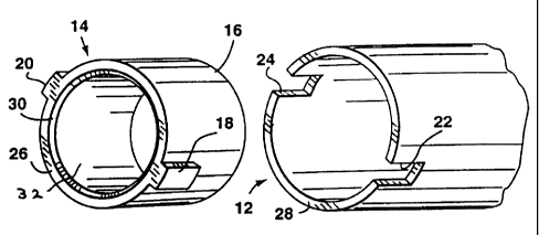
Fig. 1 is an exploded view of one end portion of a tubular core assembly in
-3-


CA 02299107 2000-02-22
accordance with one embodiment of the invention;
Fig. 2 is a perspective view of the tubular core assembly of Fig. 1 in an
assembled condition;
Fig. 3 is an exploded view of one end portion of a tubular core assembly in
accordance with a second embodiment;
Fig. 4 is a perspective view of the tubular core assembly of Fig. 3 in an
assembled condition;
Fig. 5 is an exploded view of one end portion of a tubular core assembly in
accordance with a third embodiment; and
Fig. 6 is a perspective view of the tubular core assembly of Fig. 5 in an
assembled condition.
DESCRIPTION OF PREFERRED EMBODIMENTS
Referring to the drawings, Figs. 1 and 2 show one end portion of a tubular
core assembly for a paper roll which comprises a hollow cylindrical core
member
12 of paperboard material, and an annular end member 14 of synthetic plastic
material with a sleeve portion 16 within each opposite end portion of the core
member 12. The core member 12 has multiple spirally-wound wraps (i.e.
laminated
plies) of paperboard material, and the synthetic plastic material may be of
suitable
polymeric material such as injection moulding grade 25% glass filled nylon
type 6.
The sleeve portion 16 of each end member 12 has an outer annular surface
which is a compression fit, i.e. a friction fit, in a respective end portion
of the core
member 12. Each end member 14 has a pair of diametrically opposite solid lugs
18,
20 of rectangular section projecting radially outwardly from the end of the
sleeve
-4-


CA 02299107 2000-02-22
portion 16 at the end of the core member 12. The lugs 18, 20 are located in
diametrically opposite notches 22, 24 of rectangular section in the end of the
core
member 12, and rotationally equalize continuous torque and axial pressure from
the
end members 14 to the core member 12. The lugs 18, 20 are the same size as the
notches 22, 24 so as to be a close fit therein.
Each end member 14 also has an end surface 26 adjacent the respective end
28 of the core member 12, and the end surface 26 has a radially inwardly and
rearwardly bevelled radially inner portion 30 for engagement by a chuck (not
shown) inserted into the end member 16.
Each end member 14 has an internal diameter in the range of about 3 to
about 6 inches, an outer diameter in the range of from about 3.25 to about 7
inches
and a length in the range of from about 1.5 to about 6 inches. The core member
12 has an outer diameter in the range of from about 4 to about 9 inches and a
length
in the range of from about 2 to about 10 feet. The ratio of end member roll
thickness to core member thickness is in the range of from about 0.75:1 to
about
1.5:1.
The lugs 18, 20 each have a height above the outer annular surface of the end
member 14 in the range of from about 0.2 to about 1 inch, a circumferential
width
in the range of from about 0.25 to about 3 inches, and an axial length in the
range
of from about 0.5 to about 4 inches. The notches 22,24 are of course similarly
sized.
In a specific example of the invention, the sleeve member 16 of each end
member 14 has an internal diameter of 3 inches, an external diameter of 3.75
inches
and a length of 3 inches. The core member 12 has an outer diameter of 4.4
inches
and a length of 4.5 ft, and the ratio of end member roll thickness to core
member
-5-


CA 02299107 2000-02-22
thickness is 1.15:1. Each lug 18, 20 has a height above the outer annular
surface of
the end member 14 of 0.325 inches, a circumferential width of 0.75 inches, and
an
axial length of 0.75 inches. The notches 22, 24 are of course of substantially
the
same size.
Each end member 14 has no notches and thus has an inner surface 32
extending throughout the length of the annular member 14 which is continuous
and
of constant radius around the circumference thereof, thereby reducing the
likelihood
of distortion of the end member 14 and consequent distortion of the core
member
12 when the tubular core assembly is used with a heavy paper roll. It is also
advantageous that each lug 18, 20 is solid.
Figs. 3 and 4 show a further embodiment which is generally similar to the
embodiment shown in Figs. 1 and 2, except that each end member 14 has three
solid
lugs 18,19,20 spaced at 120° intervals around the end member and the
core member
12 has three similarly located notches 22, 23, 24.
Figs. 5 and 6 show a further embodiment which is generally similar to the
previous embodiments, except that the end member 14 has four lugs 18, 19, 20,
21
spaced at 90° intervals around the end member 14 and the core member 12
has four
similarly positioned notches 22, 23, 24, 25.
Other embodiments of the invention will be readily apparent to a person
skilled in the art, the scope of the invention being defined in the appended
claims.
02111030.9pa
-6-

Representative Drawing
A single figure which represents the drawing illustrating the invention.
Administrative Status

For a clearer understanding of the status of the application/patent presented on this page, the site Disclaimer , as well as the definitions for Patent , Administrative Status , Maintenance Fee  and Payment History  should be consulted.

Administrative Status

Title Date
Forecasted Issue Date 2007-01-09
(22) Filed 2000-02-22
(41) Open to Public Inspection 2000-08-23
Examination Requested 2005-02-08
(45) Issued 2007-01-09
Deemed Expired 2014-02-24

Abandonment History

There is no abandonment history.

Payment History

Fee Type Anniversary Year Due Date Amount Paid Paid Date
Application Fee $300.00 2000-02-22
Maintenance Fee - Application - New Act 2 2002-02-22 $50.00 2002-02-07
Maintenance Fee - Application - New Act 3 2003-02-24 $50.00 2003-01-09
Maintenance Fee - Application - New Act 4 2004-02-23 $50.00 2004-01-07
Maintenance Fee - Application - New Act 5 2005-02-22 $100.00 2005-01-14
Request for Examination $400.00 2005-02-08
Maintenance Fee - Application - New Act 6 2006-02-22 $100.00 2006-01-19
Final Fee $150.00 2006-10-13
Expired 2019 - Corrective payment/Section 78.6 $750.00 2007-01-15
Back Payment of Fees $1.00 2007-01-15
Maintenance Fee - Patent - New Act 7 2007-02-22 $200.00 2007-01-15
Maintenance Fee - Patent - New Act 8 2008-02-22 $200.00 2008-01-17
Maintenance Fee - Patent - New Act 9 2009-02-23 $200.00 2009-01-21
Maintenance Fee - Patent - New Act 10 2010-02-22 $250.00 2010-01-21
Maintenance Fee - Patent - New Act 11 2011-02-22 $250.00 2011-01-17
Maintenance Fee - Patent - New Act 12 2012-02-22 $250.00 2012-01-13
Owners on Record

Note: Records showing the ownership history in alphabetical order.

Current Owners on Record
KEWIN, DANIEL D.
Past Owners on Record
None
Past Owners that do not appear in the "Owners on Record" listing will appear in other documentation within the application.
Documents

To view selected files, please enter reCAPTCHA code :


To view images, click a link in the Document Description column. To download the documents, select one or more checkboxes in the first column and then click the "Download Selected in PDF format (Zip Archive)" or the "Download Selected as Single PDF" button.

List of published and non-published patent-specific documents on the CPD .

If you have any difficulty accessing content, you can call the Client Service Centre at 1-866-997-1936 or send them an e-mail at CIPO Client Service Centre.


Document
Description 
Date
(yyyy-mm-dd) 
Number of pages   Size of Image (KB) 
Description 2000-02-22 6 260
Claims 2000-02-22 3 100
Representative Drawing 2000-08-21 1 6
Abstract 2000-02-22 1 27
Drawings 2000-02-22 2 52
Cover Page 2000-08-21 1 37
Description 2006-01-24 6 257
Representative Drawing 2006-11-23 1 10
Cover Page 2006-12-29 1 43
Fees 2002-02-07 2 98
Fees 2005-01-14 1 46
Fees 2006-01-19 1 46
Correspondence 2007-01-23 1 13
Prosecution-Amendment 2007-01-15 1 61
Assignment 2000-02-22 2 92
Correspondence 2002-01-30 1 32
Correspondence 2002-02-07 1 30
Correspondence 2002-02-19 1 12
Correspondence 2002-02-19 1 13
Correspondence 2002-04-04 3 114
Correspondence 2002-02-07 1 35
Prosecution-Amendment 2005-02-08 2 75
Prosecution-Amendment 2005-08-02 3 118
Prosecution-Amendment 2006-01-24 4 150
Correspondence 2006-10-13 1 47
Prosecution-Amendment 2007-01-15 2 73
Correspondence 2007-03-07 1 17
Fees 2008-01-17 1 45