Note: Descriptions are shown in the official language in which they were submitted.
CA 02299438 2002-10-29
ATM-BASED DISTRIBUTED VIRTUAL TANDEM SWITCHING SYSTEM
BACKGROUND OF THE INVENTION
1. Field of the Invention
The present invention relates to a telecommunications architecture.
More particularly, the present invention relates to tandem switching systems
for use
within a public switched telephone network (PSTN). The present invention
enables
voice trunking over an asynchronous transfer mode (ATM) network by replacing
tandem switches with a distributed virtual tandem switching system that
includes a high
speed ATM network. The replacement is virtual because as far as the end ofFces
are
concerned, the ATM-based distributed virtual tandem switching system is
functionally
equivalent to the traditional time division multiplexed (TDM) tandem switching
system.
2. Background Information
Within the public switched telephone network (PST2~, an originating
caller communicates with a destination by establishing a connection between an
end
oi~ce serving the originating caller and an end once serving the destination.
Fig. 1
shows the architecture of the current PSTN. In today's PSTN, end oi~ce
switches 10
are connected to each other via tandem trunk groups 12, direct trunk groups
14, or
both tandem trunk groups 12 and direct trunk groups 14. Each trunk within a
trunk
group is typically a digital service level 0 (DSO) (i.e., 64 kilobits per
second)
communication line that transmits between the end offices 10 in a time
division
multiplexed (TDM) manner. When an end once utilizes a direct trunk group 14,
the
connection between the end oiEces 10 is without
CA 02299438 2000-O1-31
WO 99/57851 PCT/US99/06555
any intermediaries. When an end/central office 10 utilizes a tandem trunk
group 12, the
connection between end offices 10 is via a tandem switch 16.
The tandem switch or office 16 is an intermediate switch or connection,
between
an originating telephone call location and the final destination of the call,
which passes the
call along. Tandem switches are often utilized to handle overflow calls. That
is, when all
paths are busy on a primary route, e.g., the direct interoffice trunk group 14
between the
originating and destination end offices 10, alternative routes through the
tandem switch 16
handle the overflow call volume. The tandem switch 16 can also function as a
physical
path to non-directly-connected offices in addition to functioning as an
overflow path for
directly connected offices. If the overflow route through the tandem switch 16
becomes
full, an alternate final route may be provided. The alternate final route is
via another end
office 10, thus employing two interoffice trunk groups 14.
Signaling is needed within the PSTN to establish a connection (i.e., setup a
telephone call) between a calling party and a destination. The signaling
enables line
acquisition and sets up call routing, in addition to performing other
functions. The
signaling can be transmitted through a channel common with the voice data (in-
band
signaling) or can be transmitted through a dedicated channel (out of band
signaling). The
dominant signaling protocol currently in use today is transmitted via the
dedicated channel
and is called Signaling System 7 (SS7).
A conventional connection setup between two end offices 20, 22 in a tandem
network is now described with reference to Figs. 2 and 3. When a calling party
19 (e.g.,
235-1111) dials a telephone number (e.g., 676-2222), the originating central
office 20
interprets the dialed digits and routes the call to either a direct
interoffice trunk group 14
between end offices 20, 22 or a pair of tandem office trunk groups 12 and the
corresponding tandem switch 16 between end offices 20, 22. Assuming the pair
of tandem
office trunk groups 12 and the corresponding tandem switch 16 is utilized, a
trunk from
each of the trunk groups 12 needs to be selected and reserved by signaling
within the SS7
network. Thus, necessary information is transmitted from the originating end
office 20 to
its associated signaling transfer point 18. Although only a single signaling
transfer point
is shown in the figures, a network typically includes many signaling transfer
points. Thus,
-2-
CA 02299438 2000-O1-31
WO 99/57851 PCT/US99/06555
each signaling transfer point 18 transfers signals from one signaling
link~~~to anot~ier'~
signaling link in the SS7 network that transports SS7 messages.
The transmitted information is in the form of an ISUP (ISDN user part)
message.
It contains a unique point code, which uniquely identifies each end office,
corresponding
to the originating end office (originating point code (OPC)) and the
destination (destination
point code (DPC)). Because the message must first go to the tandem office 16,
the ISUP
message contains the destination point code of the tandem office. The message
also
contains a circuit identification code (CIC) that corresponds to the physical
circuit that will
be employed to transport the data. Thus, interoffice trunks are identified by
originating
point code (OPC), destination point code (DPC), and circuit identification
code (CIC).
As shown in the example illustrated in Fig. 3, initially an ISUP message is
sent
containing a DPC equal to 246 1 2, an OPC equal to 246 1 1, and a CIC equal to
22.
Consequently, a circuit will be setup between the originating end office 20
and the tandem
office 16. The tandem switch 16 receives the SS7 message and determines from
the called
number, which is embedded in the protocol, where to route the call, i.e., the
appropriate
destination end office 22. Then, via the SS7 network, the call is setup
between the tandem
switch 16 and the appropriate terminating office 22 in a similar manner. Thus,
because the
tandem office 16 needs to transport the data to the destination end office 22,
the tandem
office 16 sends an ISUP message to the signaling transfer point 18, including
the
destination end office=s destination point code, i.e., 246 1 3, the tandem
office's
origination point code, i.e., 246 I 2, and the circuit identification code
corresponding to
the circuit between the tandem office 16 and the destination office 20, e.g.,
circuit 7. After
this ISUP message is sent to the signaling transfer point 18, the signaling
transfer point 18
forwards the ISUP message to the destination end office 22 in order to setup
the
connection between the tandem office 16 and the destination office 22, thus
reserving the
circuit. The terminating central office switch 22 receives the SS7 message and
determines
where to terminate the call by interpreting the called number embedded in the
protocol.
A call flow scenario is now described with reference to Fig. 2. A cailer 19
dials the
telephone number of a destination 23. The first end office 20 (end office A)
collects the
digits of the called number and checks routing tables to determine to which
end office 22
J
CA 02299438 2000-O1-31
WO 99/57851 PCT/US99/06555
the dialed telephone number belongs. Then the originating end office 20"'f
rids a"dii-ecf"
trunk group 14 between itself and the end office owning the dialed telephone
number.
Subsequently, the originating end office finds an idle trunk within the trunk
group 14. The
originating end office 20 selects and reserves the idle trunk of the trunk
group 14 and
S initiates an SS7 IAM (initial address message) message containing the
following: signaling
transfer point routing address of the destination end office; the calling
telephone number;
the called telephone number, and the trunk ID (CIC) for the selected trunk of
the trunk
group.
The signaling transfer point 18 receives the IAM message and forwards it to
the
destination end office 22. The destination end office 22 then receives the IAM
message
and uses the CIC information to reserve the selected trunk within the trunk
group 14. The
destination end office 20 (end office B) then checks the called telephone
number 23 for on-
hook and feature support and holds the line, assuming the dialed telephone
number is on
hook. The destination end office 22 then applies a ring to the line and ring
tone to the
selected trunk in the trunk group 14. Next, the destination end office 22
connects the
dialed telephone number line to the selected trunk in the trunk group 14,
initiates an SS7
ACM (Address Complete Message) message and forwards it to the signaling
transfer point
18.
The signaling transfer point receives the ACM message and forwards it to the
originating end office 20 that receives the ACM message. The originating end
office 20
then connects the calling telephone number line to the selected trunk.
Consequently, the
caller of the calling number hears a ring tone and the called party at the
called telephone
number picks up the phone. The destination end office 22 detects the off hook
on the
called telephone number 23 and removes the ring tone. The destination end
office 22 then
initiates an SS7 ANM (answer) message to the signaling transfer point 18. The
signaling
transfer point 18 receives the ANM message and forwards it to the originating
end office
20. The originating end office 20 receives the ANM message and starts
necessary billing
measurement. Ultimately, the caller speaks with the called party.
Another call flow scenario according to the prior art is now described with
reference
to Fig. 2. Initially, a caller, e.g., 235-1111 dials a destination, e.g., 676-
2222. The
-4-
CA 02299438 2000-O1-31
WO 99/57851 PCT/US99/06555
originating end office 20 (end office A) collects digits of the called~number
and'c''liec'k's'
routing tables to determine which end office handles 676. The originating end
office 20
finds that 676 belongs to a destination end office 22 (end office B). End
office A then
locates a direct trunk group 14 to end office B. Assume in this example that
no idle trunk
exist within the direct trunk group 14. Thus, end office A chooses and
reserves a first
tandem trunk group 12, and a selected trunk from the first reserved trunk
group 12.
Subsequently, end office A initiates an SS7 IAM message containing the
following:
signaling transfer point routing address of the tandem; calling telephone
number; called
telephone number; and trunk identification (CIC) for the selected trunk of the
first reserved
trunk group 12.
The signaling transfer point I8 receives the IAM message and forward it to the
tandem switch 16. The tandem office 16 receives the IAM message and utilizes
the CIC
information to reserve the selected trunk of the first reserved trunk group
12. The tandem
office 16 then checks a routing table to determine the destination and
reserves a selected
trunk of a second trunk group 12, which connects to the destination.
Subsequently, the
tandem 16 initiates an SS7 IAM message to the signaling transfer point 18 with
the
following information: signaling transfer point routing address of end office
B; calling
telephone number; called telephone number; and trunk identification (CIC) for
the selected
trunk of the second trunk group 12.
The signaling transfer point 18 receives the IAM message and forwards it to
end
office B. End office B receives the IAM message and utilizes the CIC
information to
reserve the selected trunk of the second trunk group I2. End office B checks
whether the
called telephone number is on-hook and holds the line, assuming that 676-2222
is on-hook.
End office B applies ringing to the line and a ring tone to the selected trunk
of the second
trunk group 12. End office B then connects the line to the selected trunk of
the second
trunk group 12 and initiates an SS7 ACM message to the signaling transfer
point 18.
The signaling transfer point 18 receives the ACM message and forward it to the
tandem switch 16. The tandem switch 16 receives the ACM message from the
signaling
transfer point 18 and consequently, the tandem switch initiates an ACM message
to the
signaling transfer point 18.
-5-
CA 02299438 2000-O1-31
WO 99!57851 PCT1US99/06555
The signaling transfer point 18 receives the ACM message anc~ forwards it to
end-
office A. End office A receives the ACM message and connects 235-111 I to the
selected
trunk of the first reserved trunk group 12. Next, the caller at 235-111 I
hears a ring tone
and the called party at 676-2222 picks up the phone.
Consequently, end office B detects an off hook on 676-2222. Accordingly, end
office B removes the ring tone and initiates an ANM message to the signaling
transfer
point 18. The signaling transfer point 18 receives the ANM message and
forwards it to the
tandem switch 16. The tandem switch 16 receives the ANM message from the
signaling
transfer point 18 and the tandem switch 16 initiates an ANM message to the
signaling
transfer point I 8.
The signaling transfer point 18 receives the ANM message from the tandem
switch
and forwards it to end office A. End office A receives the ANM message from
the
signaling transfer point 18 and starts necessary billing measurement. Finally,
the calling
party at 235-11 I 1 talks to the called party at 676-2222.
The current system has disadvantages. In order to minimize overflow call
volume,
the size of a trunk group needs to be forecast so that the trunk group can
handle the
expected call volume. Then, appropriately sized trunk groups are
preprovisioned, each
having a dedicated bandwidth. The process of forecasting and preprovisioning
is
expensive. Moreover, the current trunking architecture requires a large number
of small
trunk groups to link end offices because of the large number of end offices
that each end
office must connect with. This form of trunking leads to inefficiencies due to
the relatively
small size of a significant number of the trunk groups. That is, the small
size reduces the
call carrying capacity per trunk and therefore requires a larger percentage of
overflow
trunking. In addition, the large number of trunk groups requires huge
investments in
hardware and software for systems that keep track of individual interoffice
trunks. Further,
the trunk forecasting and provisioning is necessary for thousands of
individual trunk
groups.
The ATM Forum's VTOA Group has attempted to solve the problems associated
with voice trunking over ATM. The VTOA Group developed a specification for
carrying
voice over ATM in a private network environment. For example, see ATM Forum
-6-
CA 02299438 2000-O1-31
WO 99/57851 PCT/US99/06555
Technical Committee, "Circuit Emulation Service
Interoperab'ility'~pecification ~ersiori
2.0" (January 1997). That specification allows private businesses to employ an
ATM
network to establish voice channels across the ATM network using a protocol,
such as
private network-network interface (PNNI), which facilitates moving cells from
one point
in the ATM network to another point in the ATM network. However, the
specification is
limited to application within a private environment, which is not appropriate
for
applications in the PSTN. That is, interaction is not supported with systems
that include
out-of band signaling, e.g., Signaling System 7 (SS7), which is essential to
supporting
capabilities such as an advanced intelligent network (AIN).
Within these private networks, the signaling is typically in-band signaling.
Thus,
no interface with an out-of band signaling network would be required.
Moreover, if a
calling party within the private network would like to contact someone outside
of the
private network, the calling party must communicate over the normal PSTN, thus
leaving
the scope of the VTOA Group's system.
United States patent number 5,483,527 addresses voice trunking within the
PSTN.
The patent discloses a system that interposes an ATM network between two
central
offices. Signaling is sent from the central office via a signaling transfer
point (STP) to the
ATM switch. Within each ATM switch, a processing system is provided for
interfacing
the ATM switch with the STP. Thus, the ATM switches are modified to be able to
communicate with the signaling transfer point, which is a very expensive
process.
Furthermore, due to the interface being provided within each ATM switch, the
path across
the ATM network is established relatively slowly. Finally, the distributed
placement of
the interface between the signaling transfer points and the ATM network has
its own
disadvantages.
Glossary of Acronyms
AAL ATM Adaptation Layer
ACM Address Complete Message
ADPCM Adaptive Differential Pulse Code
Modulation
ADSL Asymmetric Digital Subscriber Line
AIN Advanced Intelligent Network
_7_
CA 02299438 2000-O1-31
WO 99/57851 PCT/US99106555
ANM Answer Message
ANSI American National Standards Institute
ATM Asynchronous Transfer Mode
B-ISUP Broadband ISDN User Part
CAS Channel Associated Signaling
CBR Constant Bit Rate
CCS Common Channel Signaling
CES Circuit Emulation Service
CIC Circuit Identification Code
CS-IWF Control and Signaling Interworking Function
DPC Destination Point Code
DSO Digital Signal Level 0 (64 Kbps digital signal
format)
DS 1 Digital Signal Level 1 ( 1.544 Mbps digital
signal format)
IAM Initial Address Message
1 IP Internet Protocol
S
ISDN Integrated Service Digital Network
ISUP ISDN User Part
ITU-T International Telecommunications Union - Telecommunications
IWF Interworking Function
IXC Interexchange Carrier
OAM&P Operations, Administration, Maintenance, and
Provisioning
OC12 Optical Carrier level 12 signal (622 Mbps)
OC3 Optical Carrier level 3 signal (155 Mbps)
OPC Originating Point Code
PCM Pulse Code Modulation
PNNI Private Network-Network Interface
POTS Plain Old Telephone Service
PSTN Public Switched Telephone Network
SS7 Signaling System 7
SSP Service Switching Point
_g_
CA 02299438 2000-O1-31
WO 99/5?851 PCT/US99/06555
STP Signal Transfer Point
SVC Switched Virtual Connection
TDM Time Division Multiplexing
T-IWF Trunk Interworking Function
UNI User-to-Network Interface
VTOA Voice and Telephony over ATM
SUMMARY OF THE INVENTION
In view of the foregoing, the present invention is directed to providing a
replacement for the current trunking system operating between end offices, as
well as
between end offices and an interexchange carrier network.
Accordingly, an Asynchronous Transfer Mode (ATM) based distributed virtual
tandem switching system is provided. The system comprises an ATM switching
network,
a trunk interworking function (T-IWF) device, and a centralized control and
signaling
interworking function (CS-IWF) device. The trunk interworking function (T-IWF)
device is adapted to receive end office voice trunks from time division
multiplexed (TDM)
channels and convert the trunks to ATM cells. The centralized control and
signaling
interworking function (CS-IWF) device performs call control functions and is
adapted to
interface narrowband and broadhand signaling for call processing and control
within the
ATM switching network. Thus, the ATM based distributed virtual tandem
switching
system replaces a standard tandem switch.
According to a preferred embodiment, the T-IWF includes a circuit emulation
service. Further, the T-IWF can include ATM adaptation layer 1 (AAL 1 ).
Alternatively,
the T-IWF adapts circuit traffic to ATM cells utilizing ATM adaptation layer 2
(AAL2).
If AAL2 is employed, silence suppression and/or voice compression can be
supported.
According to a preferred embodiment, each voice trunk is setup dynamically as
an
individual switched virtual connection in the ATM switching network. Moreover,
the T-
IWF and the end office switch are positioned at the same location.
According to a preferred embodiment, the narrowband signaling is SS7
signaling.
In addition, the broadband signaling is preferably PNNI, B-ISUP, and/or UNI.
-9-
CA 02299438 2000-O1-31
WO 99/57851 PCTNS99/06555
A method is provided for transporting voice from an originating location to a
destination across an Asynchronous Transfer Mode (ATM) network. The method
includes
transmitting the voice from the originating location to an originating trunk
that leaves an
end office switch; converting the originating trunk to ATM cells; and
interfacing between narrowband and broadband signaling for call processing and
control
within the ATM network. Moreover, the method includes transmitting the voice
within
the ATM cells across the ATM network utilizing the broadband signaling;
converting the
ATM cells to a destination trunk; and transmitting the voice from the
destination trunk to
the destination.
According to a preferred embodiment, the transporting is enabled by emulating
a
circuit by employing a circuit emulation service. Further, the voice may be
converted to
ATM cells utilizing ATM adaptation layer 1 (AAL 1 ). Alternatively,
the voice may be converted to ATM cells utilizing ATM adaptation layer 2
(AAL2). If
AAL2 is selected, silence suppression and/or voice compression is employed.
1 S According to a preferred embodiment, each voice trunk is setup dynamically
as an
individual switched virtual connection in the ATM network. Moreover,
converting the
originating trunk to ATM cells occurs in the T-IWF within an originating end
office and
converting the ATM cells to a destination trunk occurs in the T-IWF within a
destination
end office.
According to a preferred embodiment, the narrowband signaling is SS7
signaling.
In addition, the broadband signaling preferably is PNNI, B-ISUP, and/or UNI.
According to a preferred embodiment, an Asynchronous Transfer Mode (ATM)-
based distributed virtual tandem switching system is provided in which a
network of ATM
based devices is combined to create a distributed virtual tandem switch. The
system
includes an ATM switching network setup dynamically with individual switched
circuits.
The system also includes a trunk interworking function device and a
centralized control
and signaling interworking device. The trunk interworking function converts
end office
trunks from TDM channels to ATM cells by employing a circuit emulation
service. The
centralized control and signaling interworking function device performs call
control
functions and interfaces narrowband signaling and broadband signaling for call
processing
- 10-
CA 02299438 2000-O1-31
WO 99/57851 PCT/US99/06555
and control within the ATM switching network. Consequently, the ATM based
distri~uted"~~
virtual tandem switching system replaces a standard tandem switch.
BRIEF DESCRIPTION OF THE DRAWIN S
The present invention is further described in the detailed description that
follows,
by reference to the noted plurality of drawings by way of non-limiting
examples of
preferred embodiments of the present invention, in which like reference
numerals represent
similar parts throughout several views of the drawings, and in which:
Fig. 1 shows a prior art system for communicating between end offices;
Fig. 2 shows a known trunk group architecture;
Fig. 3 shows a known dedicated out-of band signaling network associated with a
tandem network and exemplary ISUP messages;
Fig. 4 shows an exemplary architecture of an ATM-based distributed virtual
tandem
switching system according to an aspect of the present invention;
Fig. 5 shows an exemplary architecture of an ATM-based distributed virtual
tandem
switching system including an out-of band signaling network, according to an
aspect of
the present invention;
Fig. 6 shows an exemplary trunk group architecture according to an aspect of
the
present invention; and
Fig. 7 shows an alternative architecture for an ATM-based distributed virtual
tandem switching system.
DETAILED DESCRIPTION OF THE PREFERRED EMBODIMENTS
An ATM-based distributed virtual tandem switching system is provided for
replacing standard tandem switches and facilitating the reduction of necessary
trunk groups
without decreasing call processing volume.
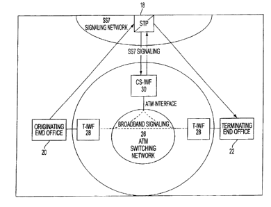
Referring now to Fig. 4, the ATM-based distributed virtual tandem switching
system according to the present invention is described. Originating end office
20 and
terminating end office 22 are similar to the central offices 10 shown in Fig.
I . The end
offices 10 are typically Class 5 switches such as the SESS available from
Lucent
-11-
CA 02299438 2000-O1-31
WO 99/57851 PCT/US99/06555
Technologies, Inc. of Murray Hill, New Jersey, or the DIVIS~100available
frorri Northei~ri
Telecom Ltd. (Nortel Networks) of Canada. 1-Iowever, any other Class ~ end
office switch
may be substituted for the Nortel and Lucent switches. Also shown is a
signaling transfer
point (STP) 18. The signaling transfer point 18 is well known in the art and
may be
provided, for example, by Alcatel of France. The signaling transfer point 18
communicates with the end offices 20, 22 via SS7 signaling as described above.
An
asynchronous transfer mode {ATM) switching network 26 is also provided. The
ATM
switches within the network can be provided by vendors such as, but not
limited to,
Lucent, Cisco Systems, Inc. of San 3ose, California, or Nortel.
A trunk interworking function (T-IWF) device 28 is also provided. Although
described as a device, the T-IWF 28 can be multiple devices or any combination
of
hardware and software. The T-IWF 28 converts end office 20, 22 voice trunks
from TDM
channels to ATM cells. More particularly, the T-IWF 28 segments the 64 Kbps
bearer
channels into ATM cells in one direction and reassembles ATM cells in the 64
Kbps
channels in the other direction. Preferably, the T-IWFs 28 are distributed
throughout the
PSTN with a T-IWF 28 corresponding to each end office 20, 22. An exemplary T-
IWF
28 is a Succession Multiservice Gateway (SMG) 4000, provided by Nortel.
However, any
other T-IWF 28 may be employed.
The ATM-based distributed network also requires a centralized control and
signaling interworking function (CS-IWF) device 30. Although described as a
device, the
CS-IWF 30 can be multiple devices or any combination of hardware and software.
The
CS-IWF 30 performs necessary call control functions as well as conversion
between a
narrowband signaling, e.g., Signaling System 7 (SS7), protocol, and a
broadband signaling
protocol for call processing and control within the ATM network. Preferably, a
single CS-
IWF 30 serves all the T-IWFs 28 in a metropolitan area. An exemplary CS-IWF 30
is a
Succession Call Server {SCS), provided by Nortel. However, any other CS-IWF 30
may
be employed.
The T-IWFs 28, the CS-IWF 30, the ATM switching network 26, and the
interconnecting links together comprise the ATM-based distributed virtual
tandem
switching system. The system is distributed because the tandem functions are
carried out
- 12-
CA 02299438 2000-O1-31
WO 99/57851 PCT/US99/06555
in part by the T-IWFs 28 that are located near the end offices 20, 22 in a
distributed
manner. The system is virtual because as far as the end offices 20, 22 are
concerned, the
ATM-based distributed virtual tandem switching system is functionally
equivalent to the
traditional time division multiplexed (TDM) tandem switching system 1 G. Thus,
end
offices 20, 22 require only slight configuration changes in order to utilize
the present
invention. The virtual aspect also refers to the fact that the individual
trunks are no longer
DSO time slots that need to be statistically provisioned. Rather, the trunks
are realized
through dynamically established ATM switched virtual connections.
Deployment of the ATM-based distributed virtual tandem switching system allows
an end office 20, 22 to handle normal call volumes while having only one or a
few large
trunk groups connecting to the ATM switching network, thus eliminating the
need to
provision separate trunk groups to different destination end offices. In
addition, the total
trunking bandwidth is shared by traffic to all destinations because ATM
virtual
connections are provisioned on demand by signaling. Consequently, bandwidth is
not
dedicated to any TDM voice channels between predetermined locations, but
rather is
dynamically shared.
According to a preferred embodiment, end offices 20, 22 have a single large
trunk
group that connects with the virtual tandem switch, although exceptions may
exist where
more than one trunk group is needed, for example, if an end office limits the
number of
members in a trunk group connected to the end office. Consequently, the direct
interoffice
trunks 14 between end offices 10 (shown in Fig. 1 ) are eliminated.
Thus, the present invention reduces the total number of trunks needed in an
end
office 20, 22, improves trunk utilization, and reduces or eliminates the task
of trunk
forecasting and provisioning. Furthermore, growth in trunking needs by the end
office
switches 20, 22 can be more easily met because the virtual tandem switching
system of the
present invention allows scalability supported by ATM networks. The
scalability is
achieved because of the ATM network's greater bandwidth and the ATM network's
statistical multiplexing, which more efficiently utilizes existing bandwidth.
The trunk
interworking function T-IWF 28 is a device that is preferably located in the
same structure
or building that houses each end office switch 20, 22. More particularly, the
T-IWF 28 is
-13-
CA 02299438 2000-O1-31
WO 99/57851 PCT/US99/06555
implemented with one or more physical devices that are external to the switch
20; 2~, ~iut
within the same end office that houses the corresponding switches) 20, 22. The
reason
for the co-location is that the sooner the TDM trunks are converted to ATM,
the earlier the
advantages of ATM statistical multiplexing gains are enjoyed. Because the T-
IWF 28 is
physically located in the central office 20, 22, the T-IWF 28 must meet the
central office
environmental requirements. In a preferred embodiment, network equipment
building
standards (NEBS) level 3 is satisfied.
Because ATM is a packet oriented rather than circuit oriented technology, ATM
must emulate circuit characteristics in order to carry constant bit rate (CBR)
traffic such
as voice. This emulation is referred to as a circuit emulation service (CES).
The T-IWF
28 converts between the 64 Kbps trunks and ATM cells by employing a well known
method of circuit emulation that is described in "Circuit Emulation Service
Interoperability
Specification Version 2.0" by The ATM Forum Technical Committee (January
1997),
which is expressly incorporated herein by reference in its entirety.
Preferably, the
structured digital service level 1 (DS 1 ) nx64 Kbps service described in the
CES
interoperating specification is employed to connect DS 1 equipment across
emulated
circuits carried on an ATM network. The structured DS 1 nx64 Kbps circuit
emulation
system efficiently carries TDM trunks through the ATM trunking network. The
structured
DS 1 CES requires ATM switches to treat one or more DSOs in a T 1 circuit as
individual
ATM virtual connections.
According to the structured DS 1 CES service, each interworking function is
connected to an ATM network 26 via physical interfaces. The physical
interfaces are
ATM user network interface (LTNI) physical interfaces that have two
characteristics or
requirements. The first requirement is that the ATM interface provides
adequate
bandwidth to carry nx64 traffic after segmentation. The second requirement is
that the
ATM interface must be able to convey timing traceable to a primary reference
source from
the ATM network to the interworking function when external connection to
network
timing is not supported. The interworking functions are also connected to
standard
constant bit rate {CBR) circuits, such as end offices 20, 22. Connected in
this manner, the
interworking functions extend the constant bit rate (CBR) circuit across the
ATM network
- 14-
CA 02299438 2000-O1-31
WO 99/57851 PCT/US99/06555
26 in a manner transparent to the switches 20, 22.
An important function of the circuit emulation service operating within the T-
IWF
28 is the adaptation of circuit traffic to ATM cells. This function is called
the ATM
adaptation. As described above, when time division multiplexed trunks are
converted to
ATM cells, the ATM adaptation process occurs. More generally, ATM adaptation
refers
to converting non-ATM formatted information into the size and format of ATM
cells. For
circuit traffic such as voice to be converted into ATM format, two adaptation
layers that
can be suitably used are ATM adaptation layer 1 (AAL 1 ) and ATM adaptation
layer 2
(AAL2). However, the present invention is not limited to AALI and AAL2 and
other
layers that can satisfactorily convert the traffic into ATM cells, such as
AALS, may be
employed.
According to one preferred embodiment, the structured DS 1 nx64 Kbps circuit
emulation service employs AAL 1 such that circuit traffic is treated as
constant bit rate
(CBR) traffic within the ATM tandem switching system. However, the system is
not
limited to AAL 1 and other protocols such as AAL2 may be adopted to
incorporate
bandwidth saving features such as voice compression and silence suppression,
which can
further improve bandwidth efficiency.
AAL 1 has been standardized in both International Telecommunications Union
Telecommunication (ITU-T) and American National Standards Institute (ANSI)
since
1993 and is preferred for use with circuit emulation services due to its
simplicity. AAL 1
is designed to support constant bit rate services and allows the specification
of peak cell
rate, cell loss ratio, and cell delay variation. Depending on implementation,
the peak cell
rate bandwidth may be dedicated or guaranteed.
There is a difference between dedicated and guaranteed bandwidth. When the
peak
cell rate bandwidth is said to be dedicated to the constant bit rate service,
no other services
can utilize any of the constant bit rate's bandwidth, even if it is not
utilized by the constant
bit rate service itself. However, if the peak cell rate bandwidth is
guaranteed to the
constant bit rate service, the unused portion of the constant bit rate's
dedicated bandwidth
can be utilized by other services, so long as the other services agree to
return the
bandwidth when the constant bit rate service needs it.
-15-
CA 02299438 2000-O1-31
WO 99/57851 PCTNS99/06555
AAL 1 introduces additional delay because each AA~,1 ATM-
conriectiori°cames
information for only a single user. With voice input at 64 Kbps, it takes
5.875
milliseconds, or approximately six milliseconds to fill an AAL 1 payload of an
ATM cell.
One alternative to AAL 1 is AAL2. AAL2 started as a contribution to committee
T 1 S 1.5, an ANSI standards subcommittee. AAL2 was later introduced to the
ITU-T Study
Group 13 on May, 1996 under the temporary name of AAL-CU where CU stood for
composite user. AAL2 has now been defined in the ITU-T Recommendation 1363.2.
AAL2 enables voice to be carried as variable bit rate (VBR) data while
maintaining
its delay sensitive nature. AAL2's support for variable bit rate (VBR) traffic
allows many
bandwidth saving features, such as voice compression and silence suppression
to be
employed. These features are discussed in more detail below.
AAL2 enables multiple users to share a single ATM connection, while allowing
each user to select a potentially different quality of service parameter. The
structure of
AAL2 also allows for the packing of short length packets into one or more ATM
cells. In
contrast to AAL 1, which has a fixed payload size, AAL2 offers a variable
payload within
cells and across cells. The variable payload provides a dramatic improvement
in
bandwidth efficiency of the structured circuit emulation over AALl .
An important aspect of AAL2 is the packet fill delay parameter. The packet
fill
delay parameter allows the network operator to set a time period during which
AAL2
protocol data units are assembled and then segmented into ATM cells. The
setting of this
parameter allows the network operator to control the cell construction delay.
This allows
the operator to trade off delay and bandwidth efficiency in order to meet the
delay
requirements of some voice connections. For example, for 64 Kbps pulse code
modulation
(PCM) voice to fill up an ATM cell, it takes six milliseconds. AAL2 can reduce
this delay
by half by setting the packet fill delay to 3 milliseconds, which would result
in each ATM
cell payload being half filled. Thus, 50% bandwidth loss is traded for 50%
less delay.
Essentially what AALI or AAL2 allow is the choice of carrying voice trunks
through an ATM network as constant bit rate traffic or variable bit rate
traffic. If voice is
sent as constant bit rate traffic, then ATM Forum's structured DS 1 nx64 Kbps
circulation
emulation service using AAL 1 is employed. If voice is sent as real time
variable bit rate
- 16-
CA 02299438 2000-O1-31
WO 99/57851 PCT/US99/06555
traffic, then AAL2 as the ATM adaptation layer is employed, thus taking
advantage oftTie
many efficiency and performance enhancing features supported by AAL2.
The ATM network 26 will now be discussed. From a physical connection point of
view, the ATM trunks between switching offices may be setup with direct point-
to-point
fibers or by means of a synchronous optical network (SONET) ring. However,
logically
ATM allows the interoffice trunks to be setup in many different ways. Thus,
within the
ATM switching network 26, originating and terminating trunks are preferably
connected
by means of virtual connections setup in one of three ways.
According to a preferred embodiment of the invention, individual switched
virtual
connections (SVC) are provided in which an ATM switched virtual connection is
established for each nx64 Kbps call. When utilizing individual switched
virtual
connections, the switched virtual connections are dynamically provisioned via
signaling
and a peak cell rate is set equal to nx64 Kbps. Available ATM network
bandwidth that
would otherwise be dedicated to carrying voice traffic can be utilized by
other data
1 S applications on a dynamic basis. Individual switched virtual connections
have the
advantage that they are automatically setup, and on demand provisioning
results in trunk
bandwidth efficiency.
According to another embodiment, a mesh permanent virtual path (PVP) is
provided. The mesh permanent virtual path establishes an ATM permanent virtual
path
across the ATM tandem network between every two end offices. Thus, the
permanent
virtual paths are manually provisioned with a peak cell rate equal to the size
of the existing
trunk group between the two end offices. As with individual switched virtual
connections,
available ATM network bandwidth that would otherwise be dedicated to carrying
voice
traffic can be utilized by other data applications on a dynamic basis. Among,
the
advantages of the mesh permanent virtual path are that little or no signaling
is required
depending upon how many virtual connections are used within the permanent
virtual paths.
That is, all that is required is getting allocated within a path; no setup is
required. In
addition, every end office perceives direct trunks with every other end
office. However,
the mesh permanent virtual path requires manual provisioning and the
preallocated and
guaranteed constant bit rate bandwidth reduces trunk bandwidth efficiency.
-17-
CA 02299438 2000-O1-31
WO 99/57851 PCT/US99/06555
According to yet another embodiment, a star permanent virtual path
is~provided.~~
With a star permanent virtual path, a single ATM permanent virtual path is
established
between each end office and the ATM tandem network. The permanent virtual path
is
manually provisioned such that only one permanent virtual path is provisioned
and a peak
cell rate is set equal to the sum of all the trunks of the end office. As with
the other two
systems, available ATM network bandwidth that would otherwise be dedicated to
carrying
voice traffic can be utilized by other data applications on a dynamic basis.
Similar to the
mesh permanent virtual path, the star permanent virtual path has the advantage
of little or
no signaling, depending on if and how virtual connections are used in the
permanent
virtual path. Moreover, each end office perceives a single tandem trunk. In
addition,
switch translation is easy because it appears that a single trunk leaves each
end office.
Thus, all traffic is directed to that trunk group. However, the star permanent
virtual path
has the drawbacks of manual provisioning, and preallocated and guaranteed
constant bit
rate bandwidth reduces trunk bandwidth efficiency.
The star permanent virtual path and the mesh permanent virtual path remove the
majority of the call setup load from the switch by utilizing manually
provisioned
permanent virtual paths. Utilizing the individual switched virtual connection
increases call
setup load due to the elimination of direct trunks. That is, calls previously
using direct
trunks will now traverse to the ATM tandem switch.
The function of the CS-IWF 30 is to bridge between narrowband signaling in the
PSTN and broadband signaling within the ATM network 26. Two types of
interoffice
signaling methods are employed in present day networks, common channel
signaling
(CCS) (i.e., narrowband signaling) and channel associated signaling (CAS). CAS
is an
older kind of signaling in which signaling information is carried in the same
bearer channel
as the user information and is of little concern to the present invention.
Because the dominant interoffice signaling protocol currently in use is
Signaling
System 7 (SS7), the CS-IWF 30 is provided for interacting with SS7 and
enabling support
of SS7 within the ATM network 26. SS7 is a common channel signal (CCS)
protocol for
call control information. The protocol is transported via a physically
separate network
3U from that of the voice bearer channels.
-18-
CA 02299438 2000-O1-31
WO 99/57851 PCT/US99/06555
With reference to Fig. 5, explanation is provided as to how the present
invention
supports the SS7 signaling within the ATM network 26 by preserving the
existing SS7
signaling process and the ISUP message integrity. The originating end office
20 sends its
ISUP message to the signaling transfer point 18 as described above.
Subsequently, the
signaling transfer point 18 forwards the message to the CS-IWF 30, which
translates
incoming ISUP messages into ATM signaling messages. For example, the unique
point
codes are translated into ATM addresses. An ATM connection is then established
between
the two T-IWFs 28 via an ATM signaling protocol such as broadband-ISDN user
part (B-
ISUP) defined by the ITU-T, PNNI defined by the ATM Forum, or UNI 3.0, 3.1,
4.0
defined by the ATM Forum. On the destination side, the T-IWF 28 composes an
ISUP
message and sends it to the signaling transfer point 18, which then completes
the
connection setup with ISUP messages to the destination end office 22.
An exemplary call flow according to the present invention is now described
with
reference to Fig. S. After the originating end office creates an ISUP message,
the
originating end office sends the ISUP message to the signaling transfer point
18. The
signaling transfer point 18 routes the ISUP message to the CS-IWF 30 via a set
of A-links
(connections between the end office and the STP). At the CS-IWF 30, the ISUP
message
is processed and call control information is distributed to the T-IWFs 28 via
the ATM
network 26. The CS-IWF 30 also formulates an ISUP message regarding the
receiving
trunk and sends it back to the signaling transfer point 18. The signaling
transfer pointl8
routes the ISUP message to the terminating end office 22. The terminating end
office then
reserves the corresponding trunk. At this point, an ATM virtual connection can
be
established between the T-IWFs 28 to carry the voice traffic. Thus, the CS-IWF
30
converts between narrowband and ATM signaling to establish connections. The
ATM
virtual connections are dynamically setup by the system via signaling as
described above
with reference to the SVCs. Although the signaling protocols must be standards
based,
such as ATM UNI or PNNI, the exact protocol may vary among implementations.
Transporting the ISUP messages from the end offices 20, 22 can be accomplished
in two ways. The ISUP messages can be carried in the SS7 network without
change, or
the ISUP messages can be carried in the ATM network in a special ATM
connection.
-19-
CA 02299438 2000-O1-31
WO 99/57851 PCT/US99/06555
According to a preferred embodiment, the ISUP messages are cazried in the SS7
netwoTk~
because it simplifies the IWF's responsibility and preserves the out of band
nature of the
SS7 signaling network.
The CS-IWF 30 should have a unique point code. For a system with a redundant
pair of CS-IWFs, two point codes may be assigned. Two sets of T1 interfaces to
a mated
pair of signaling transfer points should also be provided. In addition, an ATM
OC-3 user
to network interface (LTNI) to the ATM network should be provided. Preferably,
the CS-
IWF 30 currently supports a trunking network of at least 500,000 trunks and is
able to
connect 3,000,000 calls in a busy hour. As new processors are developed,
capacity will
increase.
Preferably, the T-IWF 28 scales from less than 100 to 16,000 trunks. Similar
to the
CS-IWF 30, as new processors are developed, capacity will increase. According
to a
preferred embodiment, the interface is T1, T3, and OC-3 compatible on the TDM
end and
DS-3, OC-3, and OC-12 on the ATM side. Preferably the ATM signals are LTNI
3.1, UNI
4.0, or PNNI 1.0 on the ATM side. Each call is earned by an ATM switch virtual
connection setup via signaling. The T-IWF 28 is a multiplexer as opposed to a
switch.
That is, the switching function is not within the T-IWF 28 for cost
considerations.
From an implementation point of view, the T-IWF 28 and the CS-IWF 30 can be
separate (as described above in the preferred embodiment), or integrated. If
they are
implemented as separate entities, one CS-IWF 30 may serve one T-IWF 28, or the
CS-
IWF 30 may centrally serve multiple T-IWFs 28.
Multiple implementations are possible for the T-IWF 28. It may be integrated
into
the switch 20, 22, may be integrated into an ATM edge switch, or may be
provided as a
stand-alone special purpose device having no switching capability. Providing
the T-IWF
28 within the ATM edge switch or as a stand-alone requires minimum or no
change to
existing switches 20, 22. Preferably, the T-IWF 28 is closely co-located with
the switch
20, 22 in the same end office in order to maximize trunking efficiency.
The CS-IWF 30 may be integrated into the switch 20, 22 or an ATM edge switch,
or may be a stand-alone, special purpose device having no switching
capability. The CS-
IWF 30 can also be integrated into the signal transfer point 18. As shown in
Fig. 7, if the
-20-
CA 02299438 2000-O1-31
WO 99/57851 PCT/US99/06555
CS-IWF 30 is part of the ATM edge switch, the ATM edge switch pre~'erab~y
opeiates~as
an integrated IWF 40, i.e., containing both the T-IWF 28 and the CS-IWF 30. In
this case
because the CS-IWF 30 and the T-IWF 28 are physically integrated into the ATM
edge
switch, they maintain a one-to-one relationship. Preferably, the ATM edge
switch is then
co-located with the switch in the end office. According to this embodiment,
the CS-IWFs
30 are seen as distributed to each end office.
According to an embodiment of the present invention, silence suppression is
employed. Silence suppression is a mechanism for saving extra network
bandwidth by not
transmitting the pauses in a voice conversation into the network. Silence
suppression can
be employed on the sender's end by not generating voice samples when the
speech level
is below a threshold. With adaptive differential pulse code modulation (ADPCM)
the
silence suppression results in fewer bits per sample during speech inactivity.
Silence
suppression can be performed in an ATM trunking network, for example, by a
voice
module on an ATM edge switch. The voice module detects silence and stops the
transmission of these silent intervals into the ATM network.
Silence suppression also suffers from side effects. For example, because
silence
suppression removes background noise, a listener may think that the line has
been
disconnected when a pause in the conversation occurs. Silence suppression also
increases
the ATM cell construction delay and adds variability to the delay. Silence
suppression
should always be disabled when fax or modem tones are detected. For ATM
trunking, the
silence suppression feature is not required, however, the availability of
silence suppression
does improve the network efficiency.
Voice compression is another way of saving network bandwidth. Voice
compression employs algorithms such as ADPCM to reduce standard PCM 64Kbps
voice
tone to 32Kbps, 24 Kbps, l6Kbps, or even 8Kbps. However, the side effects of
voice
compression are degraded voice quality and increased ATM cell construction
delay. As
with silence suppression, voice compression is not required but may be
employed in an
embodiment of the present invention.
ATM trunking for narrowband services introduces delay additional to the delay
caused by transport over the ATM network. The additional delay is primarily
associated
-21 -
*rB
CA 02299438 2000-O1-31
WO 99/57851 PCT/US99/06555
with buffering to accommodate cell delay variation introduced by the ATM
network aria -
cell construction delay. Thus, the three types of delay that voice traffic may
experience
when carried by an ATM network are: ATM switch and network transit delay,
buffering
delay in the ATM switch to accommodate cell delay variation, and ATM cell
construction
delay. While the first two types of delay are dependent on switch design,
physical
medium, distance, and traffic condition, etc., the ATM cell construction
delay, when
employing the AAL 1 circuit emulation service, is fixed. As mentioned above,
for 64Kbps
pulse code modulated (PCM) voice, it takes six milliseconds to fill an ATM
cell with a
single voice channel. The total echo path time is thus 12 milliseconds plus
additional
transit and buffering delays. For compressed voice, for example 32 Kbps using
ADPCM,
the delay will be doubled to 24 milliseconds because it now takes twice as
long to fill an
ATM cell with the speech data of a single voice channel.
In order to counteract excessive delay, appropriate echo control measures are
employed on all speech connections where end delay is significant. According
to a
preferred embodiment, an active echo control device is employed on all
connections that
exceed the total one way talk or echo transmission path of 25 milliseconds.
A call flow scenario according to the present invention is now described with
reference to Fig. 6. Initially, a calling party 19, e.g., 235-1111 dials a
destination 23, e.g.,
676-2222. The calling party' s end office 20 (end office A) collects the
dialed digits
corresponding to the called number and checks routing tables to determine the
end office
that is connected to the dialed destination. After determining the destination
end office 22
(end office B), end office A finds a trunk (e.g., trunk 6) connecting to end
office A=s T-
IWF 28. Assuming that the trunk is idle, end office A reserves trunk 6.
End office A then initiates an SS7 IAM message containing, among other
information, the following: signaling transfer point routing address of the CS-
IWF 30;
calling telephone number; called telephone number; and trunk identification
(CIC) for
trunk 6. After the signaling transfer point 18 receives the IAM message, the
signaling
transfer point 18 forwards the message to the CS-IWF 30. The CS-IWF 30, based
on the
calling telephone number, identifies the originating T-IWF 28 (T-IWF A) with
its ATM
address or other identifier. The CS-IWF 30 then sends the CIC to T-IWF A via
an ATM
-22-
CA 02299438 2000-O1-31
WO 99/57851 PCT/US99/06555
message through the ATM network (i.e., in-band signaling). The CS-IWF 3~,
based on
the called telephone number, identifies the destination T-IWF 28 (T-IWF B)
with its ATM
address or other identifier. The CS-IWF 30 then sends a request to T-IWF B for
an idle
trunk, via an ATM connection (i.e., inband signaling) in the ATM network 26.
T-IWF A receives the message from the CS-IWF 30 and based on the received CIC,
determines the corresponding DSO channel on its line interfaces. T-IWF B also
receives
a request from the CS-IWF 30. Accordingly, T-IWF B finds an idle DSO channel
on its
line interfaces and reserves it, e.g., trunk 35. T-IWF B determines the CIC
for this DS0
and sends the CIC to the CS-IWF 30 via an ATM message.
The CS-IWF 30 receives the message from T-IWF B and sends an IAM message
to the signaling transfer point 18 containing, among other information, the
following:
signaling transfer point routing address of end office B; calling telephone
number; called
telephone number; and trunk identification (CIC). The signaling transfer point
18 receives
the IAM message and forwards it to end office B.
End office B receives the IAM message and uses the received CIC to reserve the
corresponding trunk, trunk 35. End office B checks the called telephone number
for on-
hook and active call features. End office B holds the line, applies ringing to
the line and
a ring tone to trunk 35 (assuming that 676-2222 is on-hook). End office B then
connects
the line to trunk 35 and initiates an SS7 ACM message to the signaling
transfer point 18.
The signaling transfer point 18 receives the ACM message and forwards it to
the
CS-IWF 30. When the CS-IWF 30 receives the ACM message, the CS-IWF 30 sends
the
message to T-IWF A, requesting that T-IWF A establishes an ATM connection with
T-
IWF B or vice versa. That is, T-IWF B can establish a connection with T-IWF A.
In response to the received message, T-IWF A establishes a 64Kbps CBR
connection with T-IWF B. T-IWF A also maps the appropriate DSO to the outgoing
switched virtual connection. At the same time, T-IWF B associates the incoming
switched
virtual connection to the corresponding DSO. After the connection is
established, T-IWF
A sends an ATM message to the CS-IWF 30, indicating the establishment of the
ATM
connection.
The CS-IWF 30 receives the message from T-IWF A and the CS-IWF 30 sends an
- 23 -
CA 02299438 2000-O1-31
WO 99/57851 PCT/US99/06555
ACM message to the signaling transfer point 18. The signaling transfer point
18 receives
the ACM message and forwards it to end office A. End office A receives the ACM
message from the signaling transfer point 18 and connects 235-I 111 to trunk
6.
Consequently, the calling party 19 at 235-1111 hears the ringing tone. When
the
destination 23 at 676-2222 picks up the phone, end office B detects the off
hook and
removes the ringing tone. End office B then initiates an ANM message to the
signaling
transfer point 18. The signaling transfer point 18 receives the ANM message
and forwards
it to the CS-IWF 30. The CS-IWF 30 receives the ANM message from the signaling
transfer point 18 and initiates an ANM message to the signaling transfer point
18.
The signaling transfer point 18 receives the ANM message from the CS-IWF 30,
and forwards it to end office A. End office A receives the ANM message from
the
signaling transfer point 18 and starts necessary billing measurement. Finally,
the calling
party 19 at 235-11 I 1 talks to the destination 23 at 676-2222.
The present invention thus allows for savings in three broad categories: end
office
trunk termination reduction and/or growth offsets, bandwidth reduction on
transport
facilities associated with end office trunk termination reduction, and
administrative savings
associated with trunk forecasting and trunk record keeping.
The use of large trunk groups according to the present invention creates an
increased carrying capacity that results in a reduction in end office trunk
unit requirements.
The reduction allows for a decrease in capital outlays for trunk units and/or
allows for
more rapid response to the increasing trunk requirements brought about by new
traffic such
as Internet access traffic.
Bandwidth reduction on transport facilities also occurs because current
interoffice
trunks utilize bandwidth whether the trunk is in use or not. The present
invention permits
trunks to utilize bandwidth on transport facilities only when the trunk is in
use. When the
trunk is idle, no bandwidth on the transport facility is required. During low
traffic periods
such as late evenings and early mornings, available bandwidth on the transport
facilities
could increase in excess of SO%. Consequently, the bandwidth is available for
other
applications, such as data or file transfers.
Administrative savings are realized in two areas, trunk forecasting and trunk
record
-24-
CA 02299438 2000-O1-31
WO 99/57851 PCT/US99/06555
keeping. The nature of trunking today requires huge investments in hardware
and software
for systems to keep track of individual interoffice trunks. The present
invention negates
the need for such detailed record keeping by individual trunk because the
trunks are
virtual. Therefore, individual trunks spanning the network exist only when the
calls are
in progress. Consequently, keeping records on individual interoffice trunks
can be
drastically reduced.
Trunk forecasting and provisioning for thousands of individual trunk groups
can
be reduced to just a few trunk groups per end office. Call loads for the end
office can be
used to forecast trunk requirements rather than individual trunk and trunk
group
measurements. Data collection can also be simplified due to a reduction in the
amount of
data needed to accurately measure office carrying capacity loads.
According to another embodiment, the Class 5 feature set may reside within the
CS-
IWF 30. Further, a switch management system may be provided to manage all
switch
peripherals and do all OAM&P (operations, administration, maintenance, and
provisioning) for the switch. The switch management system will do paint-to-
point private
line setups.
The present invention has utility in many environments other than tandem
switching
systems, such as a wireless environment and a digital subscriber line
environment. For
wireless services, a T-IWF can be placed in the mobile switching center to
convert the
trunk traffic to ATM traffic and send it to the ATM-based virtual tandem
switch. The T-
IWF may operate with asymmetric digital subscriber lines (ADSL) by hosting the
digital
subscriber line access multiplexer (DSLAM) function.
The present invention also applies to Internet services providers. The present
invention facilitates a more efficient way of carrying dial up Internet
connections.
Currently, an Internet user typically accesses the Internet by connecting to
the Internet
service provider via a dial up modem. That style of connection consumes
resources in the
PSTN network just like a regular voice connection. However, unlike a voice
connection,
a modem connection carries bursty data with Internet Protocol (IP) packets. It
is wasteful
for bursty data to be carried by TDM circuits. Thus, the T-IWF provides an
ideal place to
implement a modem pool that terminates the dial up connections and converts
them to
- 25
CA 02299438 2000-O1-31
WO 99/57851 PCT/US99/06555
ATM connections. These ATM connections can be carried by the ATM network fo
tf~e
respective Internet service providers. Depending on the Internet service
provider's ability
to receive ATM connections, these connections may be delivered to the Internet
service
provider as ATM, or be converted back to IP packets. The modem termination
capability
on the T-IWF helps make more efficient use of network resources by carrying
Internet
traffic as data traffic using ATM connections.
The present invention also applies to broad band advanced intelligent networks
(AIN). The CS-IWF is an ideal place for broad band advanced intelligent
network
capabilities to reside. Keeping the CS-IWF as a central point of intelligence
with an open
interface allows new services and capabilities to be developed and deployed in
the entire
network very quickly.
The present invention also has applicability in provisioning leased private
lines (i.e.,
High Cap circuits). Provisioning leased private lines in today's network is a
complicated
and error prone process. Using the proposed ATM network, much of the
complexity and
provisioning can be eliminated, owing to ATM's capability of automatically
setting up
connections via signaling. Only the tail circuits at the end points need to be
manually
provisioned and maintained.
Interexchange carrier networks may also take advantage of the present
invention.
For end offices having trunks to an interexchange carrier (IXC) network, the
IXC trunks
remain time division multiplexed and unchanged. End offices not having direct
trunks to
the interexchange carrier network can choose to utilize either the time
division multiplexed
tandem network or the ATM band system to carry their traffic to the
interexchange
Garners. If the interexchange carrier trunks are carried by the ATM tandem
network, a T-
IWF will need to be placed at the interface between the local exchange carrier
and the
interexchange Garner networks to act as a gateway. For the ATM-based system, a
similar
T-IWF is provided at the interface between the local exchange carrier and the
interexchange carrier network to act as a gateway. Further, the T-IWF may be
provided
with the ability to terminate trunks from an interexchange carrier. The T-IWF
also ensures
that billing is done correctly. This arrangement applies not only to
interexchange carrier
switches, but also to switches owned and operated by independent local
telephone service
-26-
CA 02299438 2000-O1-31
WO 99/57851 PCT/US99/06555
providers or competitive local exchange carriers.
Although the invention has been described with reference to several exemplary
embodiments, it is understood that the words that have been used are words of
description
and illustration, rather than words of limitation. Changes may be made within
the purview
of the appended claims, as presently stated and as amended, without departing
from the
scope and spirit of the invention in its aspects. Although the invention has
been described
with reference to particular means, materials and embodiments, the invention
is not
intended to be limited to the particulars disclosed; rather, the invention
extends to all
functionally equivalent structures, methods, and uses such as are within the
scope of the
appended claims.
_ ?~ _