Language selection

Search

Patent 2299446 Summary

Third-party information liability

Some of the information on this Web page has been provided by external sources. The Government of Canada is not responsible for the accuracy, reliability or currency of the information supplied by external sources. Users wishing to rely upon this information should consult directly with the source of the information. Content provided by external sources is not subject to official languages, privacy and accessibility requirements.

Claims and Abstract availability

Any discrepancies in the text and image of the Claims and Abstract are due to differing posting times. Text of the Claims and Abstract are posted:

  • At the time the application is open to public inspection;
  • At the time of issue of the patent (grant).
(12) Patent: (11) CA 2299446
(54) English Title: STRIP-SHAPED OR RECIPROCATING KNIFE
(54) French Title: DISPOSITIF COUPANT ALTERNATIF OU SOUS FORME DE BANDE
Status: Deemed expired
Bibliographic Data
(51) International Patent Classification (IPC):
  • B26D 1/00 (2006.01)
  • B26D 1/46 (2006.01)
(72) Inventors :
  • BALKE, AXEL (Germany)
(73) Owners :
  • BALKE, AXEL (Germany)
(71) Applicants :
  • BALKE, AXEL (Germany)
(74) Agent: RIDOUT & MAYBEE LLP
(74) Associate agent:
(45) Issued: 2004-06-29
(86) PCT Filing Date: 1998-11-05
(87) Open to Public Inspection: 1999-05-20
Examination requested: 2000-04-06
Availability of licence: N/A
(25) Language of filing: English

Patent Cooperation Treaty (PCT): Yes
(86) PCT Filing Number: PCT/DE1998/003223
(87) International Publication Number: WO1999/024228
(85) National Entry: 2000-02-02

(30) Application Priority Data:
Application No. Country/Territory Date
197 49 561.3 Germany 1997-11-10

Abstracts

English Abstract


A strip-shaped or
reciprocating knife has at least one elongated
cutting blade (1) provided with a
plurality of cutting teeth (2) and
intermediate cutting gaps (5), the
cutting teeth {2) being provided with
additional, finer teeth (8). In
order to achieve from beginning to
end a smooth and clean cut of the
goods to be cut, the additional teeth
(8) are produced by providing
opposite tooth spaces (9) on both sides
of the knife arranged so close to
one another that sharp teeth (12) are
formed between the spaces. The
additional teeth provided on both
sides of the knife form a sharp
cutting edge which is symmetrically
arranged on both sides of the knife
and extends over the cutting teeth
(2).


French Abstract

Dispositif coupant alternatif ou sous forme de bande présentant au moins une lame coupante allongée (1) pourvue d'une pluralité de dents coupantes (2) et d'espaces coupants intermédiaires (5), ces dents coupantes (2) comportant une denture supplémentaire (8) plus fine. Dans le but d'exécuter une coupe et un sectionnement nets et sans bavures de l'article à couper et de simplifier la fabrication de ce dispositif, on produit la denture supplémentaire (8) au moyen d'entredents (9) situés des deux côtés du dispositif les uns en face des autres et placés à proximité si étroite les uns des autres qu'ils créent entre eux des dents pointues (12), de sorte que la denture supplémentaire des deux côtés du dispositif constitue un bord coupant aiguisé s'étendant au-dessus des dents coupantes (2) et symétriquement des deux côtés du dispositif coupant.

Claims

Note: Claims are shown in the official language in which they were submitted.


7
CLAIMS:
1. A strip-shaped or reciprocating knife comprising at least
one elongated cutting blade (1) provided with numerous cutting
teeth (2, 3, 4) and intermediate cutting gaps (5, 6, 7), the
cutting teeth (2, 3, 4) being provided with additional, finer
teeth (8), characterised in that the additional teeth (8) are
produced by providing opposite tooth spaces (9, 10, 11) on both
sides of the knife arranged so close to one another that sharp
teeth (12, 13, 14) are formed between the spaces and that the
additional teeth provided on both sides of the knife form a sharp
cutting edge which is symmetrically arranged on both sides of the
knife and extends over the cutting teeth (2, 3, 4).
2. Strip-shaped or reciprocating knife as per Claim 1,
characterised in that the additional teeth provided on both sides
also extend over the cutting gaps (5, 6, 7).
3. Strip-shaped or reciprocating knife as per Claim 1 or 2,
characterised in that the cutting teeth (2, 3, 4) are provided
with a land (15) on both sides.
4. Strip-shaped or reciprocating knife as per one of Claims 1
to 3, characterised in that the cutting teeth (2, 3) are of acute
design in the longitudinal cross-section.


8
5. Strip-shaped or reciprocating knife as per one of Claims 1
to 3, characterised in that the cut-
ting teeth (4) are designed in the shape of a convex curve
in the longitudinal cross-section.

Description

Note: Descriptions are shown in the official language in which they were submitted.


CA 02299446 1999-02-02
WO 99/24228 PCT/DG98/03223
1
Strip-shaped or reciprocating knife
The invention relates to a strip-shaped or reciprocating knife
with at least one elongated cutting blade provided with numer
ous cutting teeth and intermediate cutting gaps, the cutting
teeth being provided with additional, finer teeth.
A strip-shaped knife of this kind is known from DE 41 38 025
A1. The cutting edge of the strip-shaped knife disclosed in
this document consists of oblique ground surfaces on one or
both sides of the knife. If the ground surface is on one side,
the tooth spaces of the additional teeth are also provided on
one side. If there are ground surfaces on both sides, the
tooth spaces of the additional teeth are cut into the ground
surfaces in alternating sections of both sides of the knife.
If only one side of the cutting edge of the known knife has an
oblique ground surface with tooth spaces cut into it, the two
sides of the cutting edge are asymmetrical to one another
along their entire length. One disadvantage of this asymmetri-
cal design has proven to be the fact that, when cutting the
material, the knife is deflected from its linear path, trans-
verse to the direction of motion towards the side facing away
from the ground surface. Thus, a straight, smooth cut cannot
be achieved.
The fact that, on a cutting edge with ground surfaces on both
sides, the tooth spaces of the additional teeth are cut into
consecutive, alternating sections of both sides, results in
cutting sections in the tooth spaces of the additional teeth
which are offset relative to one another in the transverse di-
rection of the strip-shaped knife. The cutting sections, which
are offset relative to one another over a specific width, lead

CA 02299446 1999-02-02
WO 99/24228 fCT/UG98/03223
2
to increased frictional resistance when cutting the material.
The frictional resistance causes the knife and the cut mate-
rial to heat up. In addition, the offset of the cutting sec-
tions, which extends over a specific width, causes a loss of
material. This lost material, or other residue from the mate-
rial, easily becomes trapped in the cutting gaps and tooth
spaces of the additional teeth. If further heating occurs, the
lost material and residue clogs the knife, this being particu-
larly noticeable in the case of fresh baked goods. Thus, a
lateral offset of the cutting sections does root produce an op-
timally smooth, clean cut into and through the material.
Moreover, the manufacture of the strip-shaped knifed known
from DE 41 38 025 Al is relatively complex. In order to pro-
duce the cutting edge, the oblique ground surfaces are first
applied on both sides of the strip-shaped knife. This is fol-
lowed by the grinding of the undulating cutting teeth, the
cutting gaps and the additional teeth in specific, alternating
sections on both sides.
The present invention is based on the object of designing a
strip-shaped or reciprocating knife which ensures an optimally
smooth, clean cut into and through the material and is simple
to manufacture.
According to the invention, the object is solved in that the
additional teeth on a strip-shaped or reciprocating knife of
the type described at the beginning are produced by providing
opposite tooth spaces on both sides of the knife, arranged so
close to one another that sharp teeth are formed between the
spaces and that the additional teeth provided on both sides of
the knife form a sharp cutting edge which is symmetrically ar-
ranged on both sides of the knife and extends over the cutting
teeth.

CA 02299446 1999-02-02
WO 99/24228 !'CT/DG98/03223
3
The design of the strip-shaped or reciprocating knife accord-
ing to the invention results in a cutting blade, the cross-
section of which is synunetrical on both sides, with a cutting
section extending over the cutting teeth in she plane of sym-
metry. This reduces the frictional resistance to a minimum. A
smooth, clean cut of the material with a uniform cutting pat-
tern is achieved. The loss of material to be cut is also sub-
stantially reduced. Due to the fact that the additional teeth
provided on both sides form the cutting edge of the knife, the
separate, preceding step of grinding the cut~.ing blade in the
form of ground surfaces on both sides of the knife can be dis-
pensed with. This greatly reduces the complehity of manufac-
ture.
The fine teeth preferably extend over the entire cutting
blade, so that the cutting gaps are also provided with addi-
tional teeth.
In a particularly advantageous configuration, the fine teeth
are manufactured by applying tooth spaces on both sides, such
that teeth are formed between the tooth spaces provided and
the teeth and tooth spaces are each opposite one another on
both sides. The tooth spaces can be provided by grinding,
milling or stamping, for example.
Surprisingly, the additional teeth according to the invention
have shown that even high-speed strip-shaped knives no longer
heat up as much as conventional strip-shaped knives when cut-
ting the product. On the one hand, this contributes to the ma-
terial having far less of a tendency to clog the cutting gaps
and cutting teeth, thus resulting in a uniform cut. On the
other hand, the material to be cut can he processed at a
higher temperature, thus shortening the cooling time of, for
example, the baked goods to be cut, and enabling greater pro
ductivity of the entire production and work process.

CA 02299446 1999-02-02
WO 99/24228 1'CT/DE98/03223
4
It has also surprisingly become evident t:uat the additional
teeth substantially reduce noise generation, particularly that
of high-speed strip-shaped knives, compared to conventional
strip-shaped knives.
In a preferred configuration, the sectior~~: of the cutting
teeth and cutting gaps sharpened on both sides are formed by
the additional teeth provided on both sides.
The cutting teeth can be provided with a land on both sides.
The design of the fine cutting teeth can be adapted to the re-
quirements of the product to be cut. In particular, the cut-
ting teeth can be of acute design, such that their flanks on
both sides are of concave shape and graduai~.y merge into the
likewise concave cutting gaps. On the other r:and, the cutting
teeth can be of convex shape, such that the7r flanks on both
sides have a convex curve which merges intc the concave curve
of the cutting gaps.
Three practical examples of the invention are described in
more detail below based on the drawing. The drawing shows the
following:
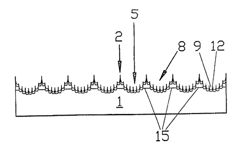
Fig. 1 A section of the cutting blade <>>f a strip-shaped
- or reciprocating knife with acute cutting teeth,
Fig. 2 A section of the cutting blade of, a strip-shaped
or reciprocating knife with acute cutting teeth,
the spacing of which is greater than, and the
height less than the cutting tips of the knife
shown in Fig. 1, and
Fig. 3 A section of the cutting blade of a strip-shaped
or reciprocating knife with cutr_ing teeth of con
vex shape.

CA 02299446 1999-02-02
WO 99/24228 1'CT/DE98/(13223
As the drawing shows, the strip-shaped or Lc.ciprocating knife
consists of at least one elongated cuttinblade 1 provided
with numerous cutting teeth 2, 3 and 4 anal intermediate cut-
ting gaps 5, 6 and 7. Cutting teeth 2, 3 ~,nd 4 and cutting
5 gaps 5, 6 and 7 are si:arpened with the sarr:e chamfer angle on
both sides.
The sharpened section.:; of cutting teeth 2, :~ and 4 and cutting
gaps 5, 6 and 7 are pLovided with additional, finer teeth 8.
Teeth 8 are produces', by grinding, milling ;r stamping tooth
spaces 9, 10 and 11 on both sides, such th._u_ teeth 12, 13 and
14 are formed between tooth spaces 9, 10 anal 11, and teeth 12,
13 and 14 and tooth ~~~aces 9, 10 and 11 are each opposite one
another on both side:. Additional teeth ~ arranged on both
sides form the sharpe~,ed sections of cutting teeth 2, 3 and 4
and cutting gaps 5, 6 and 7. A separate, ~:~receding step of
sharpening cutting teeth 2, 3 and 4 and cutting gaps 5, 6 and
7 with a specific charmer angle can thus be dispensed with.
However, cutting teeth 2, 3 and 4 are proviclF~d with a land 15
on both sides, such treat teeth 12, 13 and l~ arranged on their
tips display an acute ~:ross-section.
In the practical ex~r:L~les shown in Figs. ? and 2, cutting
teeth 2 and 3 are of acute design in the _i.,~e view. The two
practical examples ditfe'r in the space between cutting teeth 2
and 3 and in their height. .
In the practical example shown in Fig. 3, chanting teeth 4 are
of convex shape, where their flanks gradually merge into the
concave curve of cutting gaps 7.

CA 02299446 1999-02-02
WO 99/24228 I'CT/DG98/03223
6
List of reference numbers
1 Cutting blade


2 Cutting tooth


3 Cutting tooth


4 Cutting tooth


5 Cutting gap


6 Cutting gap


7 Cutting gap


8 Additional teeth


9 Tooth space


10 Tooth space


11 Tooth space


12 Tooth


13 Tooth


14 Tooth


15 Land


Representative Drawing
A single figure which represents the drawing illustrating the invention.
Administrative Status

For a clearer understanding of the status of the application/patent presented on this page, the site Disclaimer , as well as the definitions for Patent , Administrative Status , Maintenance Fee  and Payment History  should be consulted.

Administrative Status

Title Date
Forecasted Issue Date 2004-06-29
(86) PCT Filing Date 1998-11-05
(87) PCT Publication Date 1999-05-20
(85) National Entry 2000-02-02
Examination Requested 2000-04-06
(45) Issued 2004-06-29
Deemed Expired 2009-11-05

Abandonment History

There is no abandonment history.

Payment History

Fee Type Anniversary Year Due Date Amount Paid Paid Date
Application Fee $150.00 2000-02-02
Request for Examination $200.00 2000-04-06
Maintenance Fee - Application - New Act 2 2000-11-06 $50.00 2000-11-03
Maintenance Fee - Application - New Act 3 2001-11-05 $50.00 2001-10-17
Maintenance Fee - Application - New Act 4 2002-11-05 $50.00 2002-09-11
Maintenance Fee - Application - New Act 5 2003-11-05 $75.00 2003-08-22
Final Fee $150.00 2004-04-16
Maintenance Fee - Patent - New Act 6 2004-11-05 $100.00 2004-10-05
Maintenance Fee - Patent - New Act 7 2005-11-07 $100.00 2005-09-21
Maintenance Fee - Patent - New Act 8 2006-11-06 $100.00 2006-10-24
Maintenance Fee - Patent - New Act 9 2007-11-05 $100.00 2007-08-17
Owners on Record

Note: Records showing the ownership history in alphabetical order.

Current Owners on Record
BALKE, AXEL
Past Owners on Record
None
Past Owners that do not appear in the "Owners on Record" listing will appear in other documentation within the application.
Documents

To view selected files, please enter reCAPTCHA code :


To view images, click a link in the Document Description column. To download the documents, select one or more checkboxes in the first column and then click the "Download Selected in PDF format (Zip Archive)" or the "Download Selected as Single PDF" button.

List of published and non-published patent-specific documents on the CPD .

If you have any difficulty accessing content, you can call the Client Service Centre at 1-866-997-1936 or send them an e-mail at CIPO Client Service Centre.


Document
Description 
Date
(yyyy-mm-dd) 
Number of pages   Size of Image (KB) 
Representative Drawing 2000-04-06 1 4
Representative Drawing 2003-06-13 1 6
Drawings 1999-02-02 1 17
Abstract 1999-02-02 1 62
Description 1999-02-02 6 231
Claims 1999-02-02 2 41
Cover Page 2000-04-06 1 45
Claims 2003-12-12 2 37
Cover Page 2004-06-01 1 37
Assignment 1999-02-02 3 117
PCT 1999-02-02 11 372
Prosecution-Amendment 2000-04-06 1 44
PCT 2000-02-03 4 150
Prosecution-Amendment 2002-05-21 2 59
Prosecution-Amendment 2003-06-16 2 38
Fees 2003-08-22 1 30
Fees 2004-10-05 1 28
Prosecution-Amendment 2003-12-12 3 94
Fees 2001-10-17 1 30
Fees 2000-11-03 1 30
Fees 2002-09-11 1 34
Correspondence 2004-04-16 1 32
Fees 2005-09-21 1 27
Fees 2006-10-24 1 28
Correspondence 2007-08-17 1 21
Fees 2007-08-17 1 30