Language selection

Search

Patent 2299566 Summary

Third-party information liability

Some of the information on this Web page has been provided by external sources. The Government of Canada is not responsible for the accuracy, reliability or currency of the information supplied by external sources. Users wishing to rely upon this information should consult directly with the source of the information. Content provided by external sources is not subject to official languages, privacy and accessibility requirements.

Claims and Abstract availability

Any discrepancies in the text and image of the Claims and Abstract are due to differing posting times. Text of the Claims and Abstract are posted:

  • At the time the application is open to public inspection;
  • At the time of issue of the patent (grant).
(12) Patent: (11) CA 2299566
(54) English Title: DOWEL JIG
(54) French Title: GABARIT POUR CHEVILLES
Status: Deemed expired
Bibliographic Data
(51) International Patent Classification (IPC):
  • B27C 3/06 (2006.01)
  • B23B 47/28 (2006.01)
  • B25B 11/02 (2006.01)
(72) Inventors :
  • FENELON, ANTHONY DESMOND (Australia)
(73) Owners :
  • FENELON, ANTHONY DESMOND (Australia)
  • FENELON, ROSEMARIE (Australia)
(71) Applicants :
  • FENELON, ANTHONY DESMOND (Australia)
  • FENELON, ROSEMARIE (Australia)
(74) Agent: NORTON ROSE FULBRIGHT CANADA LLP/S.E.N.C.R.L., S.R.L.
(74) Associate agent:
(45) Issued: 2005-10-18
(86) PCT Filing Date: 1998-08-12
(87) Open to Public Inspection: 1999-02-25
Examination requested: 2002-04-30
Availability of licence: N/A
(25) Language of filing: English

Patent Cooperation Treaty (PCT): Yes
(86) PCT Filing Number: PCT/AU1998/000637
(87) International Publication Number: WO1999/008846
(85) National Entry: 2000-02-02

(30) Application Priority Data:
Application No. Country/Territory Date
34171/97 Australia 1997-08-13

Abstracts

English Abstract


A dowelling jig for preparing aligned bores in
corresponding joint faces of two work pieces which are to
be joined using dowels, includes a spacer plate having
opposite flat sides against which the side faces of the
work pieces are placed and held. First and second drill
guide arms are removable secured by securing arrangements
to the spacer plate and to extend away therefrom in
opposite directions, each arm providing a flat surface
against which a joint surface of one of the work pieces is
to abut. At least one line of through-bores are provided in
each of the drill guide arms for guiding a drill bit at
right angles into the work piece. The thickness of each
guide arm is such that each through-bore has an axial
length sufficient for guiding a hand held drill to drill a
work piece bore substantially at right angles to the joint
surface. The line extending along the guide arm parallel to
an edge which abuts the spacer plate and the line of
through bores on one arm corresponding in position to a
through-bores on the other arm is such that the bores align
when the joint faces of the work piece are brought into
abutment.


French Abstract

Ce gabarit possède une plaque de calage (10) contre les cotés opposés de laquelle se positionnent les faces latérales des pièces à usiner et ce, afin d'y être maintenues en place. Il est également pourvu de deux pièces guide-foret (11 12) conçues pour s'assujettir à la plaque de calage. Ces pièces partent de la plaque de calage dans deux directions opposées, constituant ainsi une surface contre laquelle vient porter une surface de joint de l'une des pièces à usiner. Dans chaque pièce guide-foret est ménagé au moins un alésage traversant qui guide l'outil de forage en le positionnant à angle droit dans la pièce à travailler. La longueur axiale de chacun de ces alésages traversant (17, 18) est suffisante pour guider un foret à main perçant un alésage dans la pièce à usiner perpendiculairement à la surface de joint. Un alésage traversant d'une pièce guide-foret correspond par sa position à un alésage traversant de l'autre pièce guide-foret et, de ce fait, ces alésages se trouvent dans un même alignement lorsque les surfaces de joint de la pièce à usiner viennent appuyer l'une contre l'autre.

Claims

Note: Claims are shown in the official language in which they were submitted.


-9-


THE CLAIMS DEFINING THE INVENTION ARE AS FOLLOWS:

1. A dowelling jig for guiding a drill for preparing
aligned bores in corresponding joint faces of two work
pieces which are to be joined using dowels, each work
piece having a side face at right angles to its joint
face, the jig comprising:
(a) a spacer plate having opposite sides against
which the side faces of the work pieces are to
be placed and held,
(b) first and second drill guide arms adapted to be
secured to the spacer plate and to extend away
therefrom in opposite directions, each arm
providing a flat surface against which a joint
surface of one of the work pieces is to abut,
(c) at least one through-bore in each of the drill
guide arms for guiding a drill bit at right
angles into the work piece, each through-bore
having an axial length sufficient for guiding a
hand held drill to drill a work piece bore
substantially at right angles to the joint
surface, and
(d) a through-bore on one arm corresponding in
position to a through-bore on the other arm such
that the bores align when the joint faces of the
work piece are brought into abutment.
2. A dowelling jig as claimed in claim 1 and wherein the
dowelling jig is T-shaped in end view, the leg of the
T acting as the spacer plate and also having
through-bores to facilitate the boring of further
drill holes in the side face of the work piece.


-10-


3. A dowelling jig as claimed in claims 1 or 2 wherein
the dowelling jig further comprises a stop plate which
is detachably mounted to one end of the jig and when
in position acts as a stop against which an end face
of the work piece is in use inserted.
4. A dowelling jig as claimed in claim 3 wherein the stop
plate is detachably mounted to one end of the jig by
means of mounting members which engage with
corresponding mounting member receiving means located
on one end face of the spacer plate.
5. A dowelling jig as claimed in claim 4 wherein the
mounting member comprises a screw and the
corresponding mounting member receiving means
comprises a threaded bore.
6. A dowelling jig as claimed in any one of claims 1 to 5
and wherein the drill guide arms are adapted to be
fixed and clamped to the respective sides of the
spacer plate by spaced screws which extend through the
arms and the spacer plate, the jig further including a
screw threaded clamp member into which the free ends
of each fixing screw is threadably inserted to clamp
the components together.
7. A dowelling jig as claimed in claim 6 wherein the
dowelling jig further includes spacer elements which
are optionally selected for insertion between one or
both of the drill guide arms and the spacer plate to
vary the spacing from the spacer plate of the
respective through-bores, whereby the device is
adapted to accommodate work place configurations of
different thickness and dowel positions relative to
the work piece side face.
8. A dowelling jig as claimed in claim 6 or claim 7,


-11-


wherein the dowelling jig further comprises a stop
plate which is detachably mounted to one end of the
jig and when in position acts as a stop against which
an end face of the work piece is in use inserted and
wherein the stop plate is detachably mounted to one
end of the jig utilising one of the spaced screws.
9. A dowelling jig as claimed in claim 8 wherein the stop
plate is substantially L-shaped and comprises a stop
portion which acts, when in position, as a stop
against which the end face of the work piece is in use
inserted, and a mounting portion which is arranged to
engage with the one of the spaced screws in a manner
such that the stop plate is detachably mountable to
one end of the jig.
10. A dowelling jig as claimed in claim 9 wherein a width
of the clamp portion does not exceed the thickness of
the drill guide arms.
11. A dowelling jig as claimed in any one of claims 1 to
wherein each of the drill guide arms has at least
first and second sets of through-bores, one set being
of a first diameter and the other set being of a
second diameter for guiding drill bits of different
diameter, the arms being arranged such that
through-bores being of the same diameter are
corresponding in position on the guide arms such that
the bores being of the same diameter align when the
joint faces of the work pieces are brought into
abutment.
12. A dowelling jig as claimed in claim 11 wherein the
sets of through-bores are each arranged in a row
extending along the drill guide arms.
13. A dowelling jig as claimed in claim 12 wherein the


-12-

arms are reversible so that either set of
through-bores can be closer to the spacer plate in
use.

14. A dowelling jig as claimed in any one of claims 1 to
14, wherein each drill guide arm is of a substantial
thickness and of relatively hard material resistant to
being enlarged inside by unintended contact with a tip
of a drill.

15. A dowelling jig as claimed in claim 14 wherein the
thickness of each drill guide arm is from about 15 to
20mm and is being made from hardened metal.

16. A dowelling jig as claimed in any one of claims 1 to
15 wherein the dowelling jig is adapted to be hand
held so that the respective work pieces can simply be
held in the desired drilling position with one hand
and an electric drill can be used to drill the bores.

17. A dowelling jig as claimed in claim 16 wherein the
length of the dowelling jig is of the order of 10cm.

18. A dowelling jig adapted to be assembled from a kit of
parts for guiding a drill to bore joint faces of
workpieces for receiving dowels whereby a joint is
formed when the workpiece joint faces are brought
together, the jig having:
(a) an abutment plate having flat opposed sides
against which a side face which is perpendicular
to the joint face of a workpiece, can be abutted
and held,
(b) first and second generally planar drill guide
plates each having a line of drill guide bores
therethrough and extending along a line parallel
to an edge face which is adapted to be clamped


-13-

to the abutment plate,
(c) spaced, corresponding transverse bores through a
substantially central plane of each of the guide
plates and through the abutment plate for
receiving elongate securing elements,
(d) clamping means for engaging the securing
elements when installed to clamp the guide
plates to the abutment plate at right angles,
(e) each guide plate having a thickness to provide
guiding of a hand held drill passing through a
bore to drill a workpiece at right angles to a
joint face, and
(f) the drill guide plates being capable of
assembly:
(i) end-to-end to one side of the abutment
plate,
(ii) on opposite sides of the abutment plate in
a mirror-image configuration of the
respective lines of drill guide bores, or
(iii) with spacer means of selected thickness
mounted between the abutment plate and
each guide plate to position the line of
guide bores a desired distance from the
edge of the workpiece.

19. A dowelling jig as claimed in claim 18, wherein the
jig further includes:
(a) a stop plate adapted to be detachably mounted to
an end of the jig to provide an abutment stop
for a workpiece.


-14-

20. A dowelling jig as claimed in claim 19, wherein the
stop plate is of an L-shaped configuration with an
arm extending perpendicularly from a planar main
portion which provides the abutment stop for the
workpiece, the arm being adapted to be clamped to an
edge of one of the guide plates.

21. A dowelling jig as claimed in any one of claims 18 to
20, wherein each line of drill guide bores is
uniformly and regularly spaced along the associated
guide plate and the transverse bores are centrally
located through the guide plates and extend along
respective axes at right angles in the central plane
and at locations midway between adjacent guide bores
near the ends of the guide plate.

22. A dowelling jig as claimed in any one of claims 18 to
21, wherein the guide plates are identical and each
has a second line of drill guide bores of different
diameter to the first line of guide bores and
extending along a second line parallel to the first
line, each guide plate being rectangular with side
edges at right angles to the faces of the guide plate
whereby either may be placed in abutment with the
abutment plate.

23. A dowelling jig as claimed in any one of claims 18 to
22, wherein the elongate securing elements comprise
screws which are a clearance fit through the
transverse bores and the clamping means comprises an
elongate strip having threaded bores spaced there
along and corresponding in position to the transverse
bores for threadably engaging the screws and thereby
clamping the dowelling jig together.

24. A dowelling jig as claimed in any one of claims 18 to


-15-

23, wherein the guide plates are about l5mm to 20mm
thick and are of hardened metal.

25. A dowelling jig as claimed in any one of claims 18 to
24, wherein each guide plate is of rectangular form
of the order of 10cm long.

26. A dowelling jig as claimed in any one of claims 18 to
25, and further including spacer elements adapted to
be selected for insertion between the edge of each
guide plate and the abutment plate and mounted on the
securing elements whereby the spacing of the line of
guide bores relative to the edge of the workpiece can
be selected.

27. A method of forming dowel joints between work pieces
comprising:
(i) taking a dowelling jig having:
(a) an abutment plate having flat opposed
sides against which a side face which is
perpendicular to the joint face of a
workpiece, can be abutted and held,
(b) first and second generally planar drill
guide plates each having a line of drill
guide bores therethrough and extending
along a line parallel to an edge face
which is adapted to be clamped to the
abutment plate,
(c) spaced, corresponding transverse bores
through a substantially central plane of
each of the guide plates and through the
abutment plate for receiving elongate
securing elements,


-16-

(d) clamping means for engaging the securing
elements when installed to clamp the guide
plates to the abutment plate at right
angles,
(e) each guide plate having a thickness to
provide guiding of a hand held drill
passing through a bore to drill a
workpiece at right angles to a joint face,
and
(f) the drill guide plates being capable of
assembly:
(1) end-to-end to one side of the
abutment plate,
(2) on opposite sides of the abutment
plate in a mirror-image
configuration of the respective
lines of drill guide bores, or
(3) with spacer means of selected
thickness mounted between the
abutment plate and each guide plate
to position the line of guide bores
a desired distance from the edge of
the workpiece,
(ii) assembling the dowelling jig into a separate
configuration,
(iii) using the jig to guide a drill into
corresponding dowel bores in the workpieces,
(iv) inserting dowels into the bores, and
(v) assembling the joint to form a product.


-17-

28. A product having at least one dowel joint between
workpiece components and formed by the method of
claim 27.

Description

Note: Descriptions are shown in the official language in which they were submitted.


CA 02299566 2002-04-30
9-1607-45
- 1 -
DOWEL JIG
The present invention relates to a dowelling jig
which is used to guide a drill to .form bores in respective
work pieces in accurately corresponding positions so that a
dowel or bolts can be inserted into the corresponding
bores, and joint surfaces of the work pieces brought
together to form an accurate joint.
Complex and expensive workshop tooling is available
to aid the drilling of bores for receiving dowels in joints
which are extensively used in woodworking. One system has
been devised to use biscuit-shaped connection elements
instead of cylindrical dowels but in each case, complex and
expensive machinery is used and intended for workshop use.
Furthermore, simple marking guides have been available to
assist the drilling of bores for dowels but because
considerable accuracy is required for the formation of a
successful joint it is important that significant skill,
care arid attention is used if successful and neat joints
are to be formed.
Examples of commonly required dowelling joints are
in right angle joints between posts and rails in furniture,
mitre joints in picture frames and joints between the edges
of boards which are formed together, for example, to
provide a table top. This latter application can be
considered particularly demanding because a series of
spaced dowels are required and any misalignment of a single
bore will create problems. It is highly desirable that the
joint when formed is neat and essentially no further
working upon the surfaces of the joint is required. For
example, with moulded products such as picture frames and
the like; it is most important that the joint faces meet


CA 02299566 2002-04-30
9-1607-45
precisely and neatly and require no more than light
sanding.
Although the invention is not confined to
embodiments when the dowelling jig is hand held,; an
embodiment which facilitates the hand holding of the work
piece and the jig is highly desirable. This permits a high
degree of portability. and use in a simple workshop or on a
site where a construction work is taking place. There :is a
need for a device which can be used without high levels of
skill or particular attention and yet the drilling process
can be effected very speedily. Thus at least preferred
embodiments of the invention lend themselves to significant
practical advantage both to professionals who can operate
easily and speedily with a simple hand held electric drill
or even an unskilled handyman.
According to the present invention, there is
provided a dowelling jig for guiding a drill for preparing
aligned bores in corresponding joint faces of two work
pieces which are to be joined using dowels each work piece
having a side face at right angles to its joint face, 'the
j ig compr,ising
(a) a spacer plate having opposite sides against
which the side faces of the work pieces are to be placed
and held,
(b) first and second drill guide arms adapted to
be secured to the spacer plate and to extend away therefrom
in opposite directions, each arm providing a surface
against which a j oint surf ace of one of the work pieces is
to abut,

CA 02299566 2002-04-30
9-1607-45
- 3 -
(c) at least one through-bore in each of the drill
guide arms for guiding a drill bit at right angles into the
work piece, each through-bore having an axial length
sufficient for guiding a hand held drill to drill a'-work
piece bore substantially at right angles \to the joint
surface, and
(d) a through-bore on one arm corresponding in
position to a through-bore on the other arm such that the
bores align when the joint faces of the work piece are
brought into abutment.
Preferably the dovuelling jigs are T-shaped.in end
view, the leg of the T acting as the spacer plate and also
having through-bores to facilitate the boring of further
drill holes in the side face of the work piece, the
dowelling jig further comprising a stop plate which is
detachably mounted to one end of the T-shaped structure and
when in position acts as a stop against which an end face
of the work piece is inserted.
In a preferred embodiment of the invention the
drill guide arms are adapted to be fixed and clamped to the
respective sides of the spacer plate by spaced screws which
extend through the arms and the spacer plate, the ,jig
further including a screw threaded clamp member into which
the free ends of each fixing screw is threadably inserted
to clamp the components together, the dowelling jig further
including spacer elements which are optionally selected for
insertion between one or both of the drill guide arms; and
the spacer plate to vary the spacing from the spacer p7.ate
of the respective through-bores, whereby the device is
adapted to accommodate workplace configurations of
different thickness and dowel positions relative to the
work piece side face, each of the drill guide arms having

CA 02299566 2002-04-30
9-1607-45
- 4 -
at least first and second sets of through bores, one set
being of a first diameter and the other set being'the
second diameter for guiding drill bits of different
diameter; the arms being reversible so that either set of
through bores is closer to the spacer plate.
A preferred embodiment of the invention is one in
which each drill guide arm is of a substantial thickness
and of relatively hard material resistant to being enlarged
inside by unintended contact with a tip of a drill; the
thickness of each drill guide arm being preferably l5 to 20
mm and being of hardened metal.
Preferably the entire unit is adapted to be hand
held so that the respective work pieces can simply be held
in the desired drilling position with one hand an electric
drill used to drill the bores. In this embodiment the
length of the dowelling jig is advantageously of the order
of 10 cm.
The drilling j ig can be supplied as a kit of parts
adapted to be assembled by the user into the desired form.
The kit usefully can include at least one secondary spacer
of the same thickness as the spacer plate and this is
adapted to be inserted between the work pieces at a remote
location and preferably a simple hand clamp is used so that
the work pieces over an extended length are spaced apart by
the desired amount. At least after the drilling of the
first set of dowel holes, the optional end can be pivoted
away or unscrewed from its position whereby the dowelling
jig can be simply slid along the elongated' work pieces.
This is most useful when, for example, joining together 'the
long boards.

. CA 02299566 2002-04-30
9-1607-45
- 5 -
For illustrative purposes only, embodiments of the
invention will now be described with reference to. the
accompanying drawings, of which:
FIG. 1 is a perspective view of a first embodiment
of the invention when assembled;
FIG. 2 is a plan view of the first embodiment of
the invention when assembled;
FIG. 3 is a side view of the first embodiment of
the present invention when assembled;
FIG. 4 is an end view of the first embodiment of
the present invention when assembled;
FIG. 5 is a cross sectional view illustrating the
utilisation of the first embodiment in accordance with the
scope of the present invention;
FIG. 6 is a cross sectional view of two work pieces
joined after utilisation of the first embodiment of the
present invention; and
FIG. 7 is a perspective view of a second embodiment
of the invention when assembled.
The illustrated embodiment is a device adapted to
be hand held and can be-used for a wide range of dowelling
joints to be formed in pre-cut and finished components.;
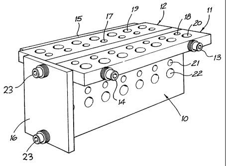
Turning initially to FIG. 1, the jig comprises a
main plate 10, side arms 11 and 12 and a pair of clamp
screws I3 and 14 which pass through the side arms and the
main plate 10 to clamp the components together using a
clamping ,member 15 having respective screw threaded bores
into which the ends of the clamp screws engage.


CA 02299566 2002-04-30
- 6 -
9-1607-45
Alternatively, wing nuts could be used instead of a
clamping strip.
This embodiment includes end stop 16 having its own
secondary clamp screw 23 which is screw threadably engaged
into a threaded blind bore in the end of the main plate 10.
The drawings illustrate one possible array of
through-bores formed in each side arm (see also FIG. 2).
The through bores comprise in this example a first set of
through bores 17 and 18 of 6 mm diameter and, in this
assembly; positioned nearer the main plate 10 and a second
set of through bores 19 and 20 of 8 mm diameter positioned
further away from the spacer plate.
This embodiment also incorporates an optional set
of through-bores 21 of 6 mm diameter and through bores 22
of 8 mm diameter in the main plate 10 as illustrated in
FIG. 3. The additional through-bores in the main plate do
permit the work piece to be bored as desired on both an end
face and a side face.
Hardened steel would be a suitable material for at
least the side arms so that inadvertent wear on the bores
due to drilling operations does not readily occur but other
materials could be used.
To provide adjustability of the line along which
bores are formed relative to the side face of the 'work
piece, the respective side arms may be rotated 180° from
the configuration shown in the drawing so that the 8 mm
sets of bores are closer to the main plate and therefore
the edge of the work piece. Furthermore adjustability.can
readily be provided for by the provision packing elements;
conveniently standard washers which can be inserted over,


. . CA 02299566 2002-04-30
9-1607-45
_ 7 _
each screw and between the main plate 10 and the adj acent
side arms 11 and 12 so that symmetric (or even if desired
asymmetric) spacing can be achieved (see also FIG. 4).
It has been found that at least this preferred
embodiment of the invention is easy and accurate to use
without special skills or even good eyesight, even with
demanding applications. Tests have been conducted on thin
hardwood planks which are preferably about 15 to 20 mm
thick and are obtained by surface dressing, disused timber
palings as used in fences. Accurate joints have readily
been formed e.g. for furniture purposes requiring minimal
final surface finishing and with minimal risk of work piece
splitting or cracking. The joining of such thin boards is
particularly difficult, yet a hand held device has proved
successful. In FIGS. 5 and 6, there is illustrated the
utilisation of the described preferred embodiment in
joining to work pieces 24, 25.
Turning now to FIG. 7, there is shown an
alternative embodiment of the jig. The jig comprises a'main
plate 30, side arms 32 and 34 and a pair of . clamp screws
36. In this embodiment, the jig comprises an alternative
end stop 38 when compared to the embodiment illustrated in
FIG. 1 (see end stop 16) . The end stop 38 is substantially
an L-shaped plate having a wider stop portion 40 and a
narrower clamp portion 42. The width of the clamp portion
42 is in this embodiment chosen to be equal to the
thickness of the side arm 32, whereas the width of the stop
portion 40 is larger than the thickness of the side arm 32
in order'to provide in use a stop surface to position work
pieces underneath the side arms. The stop portion 40 is
longer than the width of the side arms 32, 34 to provide a
stop surface underneath both the side arm 32 and 34 at the

CA 02299566 2002-04-30
9-1607-45
_ 8 _
same time: The end stop 38 is clamped to the jig utilising
one of the clamp screws 36. The clamp portion 42 comprises
a slot 44. The width of the slot 44 is substantially the
same as the thickness of the stem of the clamp screw 36,
i.e. smaller than the head portion 48 of the clamp screw
36. The clamp screw 36 is in this embodiment utilised to
mount the end stop to the jig and at the same time to hold
the side arms 32, 34 and the main plate 30 together. In the
embodiment illustrated in FIG. 7, the thickness of the main
plate 30 can be reduced when compared to the embodi:inent
illustrated in FIG. 1 aS there is no requirement to provide
corresponding threaded blind bores in the main plate to
mount the end stop to the jig. The main plate 30 may
further comprise a set of through-bores to permit a work
piece to be bored as desired on both an end face and a ide
face. It is noted that the thickness of the main plate
should in that case be sufficient to guide a drill.
If the thickness of the end stop 38 is chosen to be
the same as the thickness of the main plate 30, the'end
stop 38 rnay alternatively be used as a spacer plate to be
inserted between the work pieces at a remote location so
that the work pieces over an extended length are spaced
apart by the desired amount given by the main plate 30.
The embodiments shown in the drawings typically
will have a length of around 10 czn; main spacer plate
height of about 50 mm and a thickness of the side arms is
around 15 to 20 mm.

Representative Drawing
A single figure which represents the drawing illustrating the invention.
Administrative Status

For a clearer understanding of the status of the application/patent presented on this page, the site Disclaimer , as well as the definitions for Patent , Administrative Status , Maintenance Fee  and Payment History  should be consulted.

Administrative Status

Title Date
Forecasted Issue Date 2005-10-18
(86) PCT Filing Date 1998-08-12
(87) PCT Publication Date 1999-02-25
(85) National Entry 2000-02-02
Examination Requested 2002-04-30
(45) Issued 2005-10-18
Deemed Expired 2013-08-13

Abandonment History

There is no abandonment history.

Payment History

Fee Type Anniversary Year Due Date Amount Paid Paid Date
Application Fee $150.00 2000-02-02
Maintenance Fee - Application - New Act 2 2000-08-14 $50.00 2000-02-02
Registration of a document - section 124 $100.00 2000-03-07
Maintenance Fee - Application - New Act 3 2001-08-13 $50.00 2001-07-20
Request for Examination $200.00 2002-04-30
Maintenance Fee - Application - New Act 4 2002-08-12 $50.00 2002-07-29
Maintenance Fee - Application - New Act 5 2003-08-12 $75.00 2003-07-28
Maintenance Fee - Application - New Act 6 2004-08-12 $100.00 2004-07-16
Final Fee $150.00 2005-07-05
Maintenance Fee - Application - New Act 7 2005-08-12 $100.00 2005-07-19
Back Payment of Fees $100.00 2006-07-19
Maintenance Fee - Patent - New Act 8 2006-08-14 $100.00 2006-07-19
Maintenance Fee - Patent - New Act 9 2007-08-13 $200.00 2007-08-07
Maintenance Fee - Patent - New Act 10 2008-08-12 $250.00 2008-07-11
Maintenance Fee - Patent - New Act 11 2009-08-12 $450.00 2009-08-31
Maintenance Fee - Patent - New Act 12 2010-08-12 $450.00 2010-11-04
Maintenance Fee - Patent - New Act 13 2011-08-12 $450.00 2011-08-17
Owners on Record

Note: Records showing the ownership history in alphabetical order.

Current Owners on Record
FENELON, ANTHONY DESMOND
FENELON, ROSEMARIE
Past Owners on Record
None
Past Owners that do not appear in the "Owners on Record" listing will appear in other documentation within the application.
Documents

To view selected files, please enter reCAPTCHA code :


To view images, click a link in the Document Description column. To download the documents, select one or more checkboxes in the first column and then click the "Download Selected in PDF format (Zip Archive)" or the "Download Selected as Single PDF" button.

List of published and non-published patent-specific documents on the CPD .

If you have any difficulty accessing content, you can call the Client Service Centre at 1-866-997-1936 or send them an e-mail at CIPO Client Service Centre.


Document
Description 
Date
(yyyy-mm-dd) 
Number of pages   Size of Image (KB) 
Representative Drawing 2005-10-12 1 16
Cover Page 2005-10-12 1 52
Abstract 2000-02-02 1 61
Representative Drawing 2000-04-07 1 10
Description 2000-02-02 7 333
Drawings 2000-02-02 4 89
Claims 2000-02-02 4 175
Abstract 2002-04-30 1 41
Claims 2002-04-30 7 316
Cover Page 2000-04-07 2 65
Description 2002-04-30 8 398
Claims 2004-11-08 9 283
Prosecution-Amendment 2004-01-28 1 34
Correspondence 2000-03-27 1 2
Assignment 2000-02-02 7 271
PCT 2000-02-02 9 366
Assignment 2000-05-19 2 71
Prosecution-Amendment 2002-04-30 18 824
Prosecution-Amendment 2002-04-30 2 48
Prosecution-Amendment 2004-06-30 2 47
Prosecution-Amendment 2004-11-08 11 337
Correspondence 2005-07-05 1 40
Correspondence 2007-07-31 1 40
Correspondence 2007-10-17 2 47