Note: Descriptions are shown in the official language in which they were submitted.
CA 02299708 2000-02-29
METHOD AND APPARATUS FOR PACKAGING BULK BAGS
FIELD OF THE INVENTION
The present invention relates to container bags known as bulk bags or flexible
intermediate bulk containers (FIBC's), and more particularly to a method and
apparatus
for packaging empty, used bulk bags into a sealed container for re-use or
disposal.
BACKGROUND OF THE INVENTION
Bulk bags are increasingly employed in cargo handling and transporting
situations, particularly for the handling of fine, cohesive, powdery bulk
materials. Bulk
bags are preferred by customers whose requirements for such materials fall
between
the extremes of bulk delivery and low volume paper sack delivery. Bulk bags
typically
have a volume of about 20 to 75 cubic feet, and typically comprise a single
layer of
woven polypropylene. These bags may also have an inner liner of sheet
material,
typically a polyolefin such as polyethylene.
Bulk bags typically have a closable filling opening which can also be used for
ventilation
during emptying, and the bottom is typically provided with a bag outlet which
is
tightened and tied with one or more cords or held in position with a clip.
During emptying of bulk bags, precautions are typically taken to minimize the
release of the powdered contents of the bags into the working environment.
After the
bulk bags are emptied, they are typically collected for re-use or disposal by
packing
them into other bags or rigid containers such as boxes. Although the emptied
bulk
bags can contain significant residual amounts of powdered materials, few
precautions
are typically taken to prevent the release of powdered materials into the work
environment during the collection and packaging of the emptied bulk bags. The
release
of such materials, even in relatively small quantities, may be undesirable
both from a
health and safety standpoint, and due to the risk of contamination of other
products.
CA 02299708 2000-02-29
-2-
One system known to the applicant for packaging of empty bulk bags is to pack
the bags into an open-topped cardboard container, known as a "gaylord box",
and to
compress the bags within the box with a metal plate fitted with a vacuum port
through
which dust given off by the bags is withdrawn. While this system somewhat
reduces
the amount of dust released during packing the empty bulk bags, it does not
provide a
complete solution to the problem of dust release during handling of the
emptied bulk
bags.
SUMMARY OF THE INVENTION
The present invention overcomes the above-discussed problems of the prior art
by providing a method and apparatus for packaging empty bulk bags into a rigid
bag
container which eliminates or significantly reduces the amounts of powdered
materials
released into the working environment during collection and packaging of empty
bulk
bags.
The apparatus of the present invention provides a packing enclosure in which a
rigid bag container such as a gaylord box is received through an access
opening. The
packing enclosure has a resealable opening through which empty bags can be
inserted
into the open top of the rigid container.
The apparatus of the present invention is also provided with a bag compressor,
which is preferably in the form of a metal plate or a heavy hollow lid which
is initially
positioned above the resealable opening through which the bags are inserted,
and
which is movable downwardly into the box to compress the empty bags.
Thus, the present invention provides a compact, relatively inexpensive
apparatus
which takes up substantially the same amount of floor space as a gaylord box,
and
which is effective to prevent the release of dust into the atmosphere during
collection
and packaging of empty bulk bags.
CA 02299708 2000-02-29
-3-
BRIEF DESCRIPTION OF THE DRAWINGS
The invention will now be described, by way of example only, with reference to
the accompanying drawings, in which:
Figure 1 is a front elevation view of a preferred apparatus according to the
present invention, with the bag compressing plate suspended above the packing
enclosure;
Figure 2 is a side elevation view of the apparatus of Figure 1, also with the
bag
compressing plate suspended above the packing enclosure;
Figure 3 is a perspective view of the packing enclosure of Figure 1 and a
gaylord
box which may be used with the apparatus of Figure 1;
Figure 4 is a perspective view of the bag compressing plate of the apparatus
of
Figure 1;
Figure 5 is a cross-sectional side elevation view of the bag compressing plate
taken along the line 5 - 5' in Figure 4; and
Figures 6 to 9 are front elevation views illustrating a preferred method of
use of
the apparatus of Figure 1.
DETAILED DESCRIPTION OF PREFERRED EMBODIMENTS
A preferred apparatus and method according to the present invention is now
described below with reference to the drawings. The following description
relates to the
packaging of bulk bags into a gaylord box. However, it will be appreciated
that the
principles of the present invention are applicable to the packaging of bulk
bags into any
rigid container.
The term "bulk bags" as used throughout this application is intended to
include
within its scope flexible intermediate bulk containers (FIBC's) and other
flexible
containers for handling powdered bulk materials. Such containers may also be
referred
CA 02299708 2000-02-29
-4-
to as "big bags", "supersacks", etc. The bulk bags packaged according to the
present
invention preferably have the capacities disclosed above, and typically
measure about
35 inches wide by about 50 inches tall.
The dimensions of the apparatus 10 given below are for use in association with
a
substantially cubic gaylord box 24 having a height of about 40 inches, sides
28 having
lengths of 44 and 48 inches, with a closed bottom 26, an open top 30, and a
removable
cover 32. For ease of reference, the longer sides of box 24 are referred to by
reference
number 28a and the shorter sides of box 24 are referred to by reference number
28b.
The gaylord box 24 is preferably constructed from cardboard or other rigid
material.
The structure of a preferred apparatus 10 according to the invention will now
be
discussed below with reference to Figures 1 to 5.
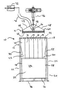
Preferred apparatus 10 comprises a packing enclosure 12 and a bag
compressing plate or "tamper" 14 having a dust extraction port 16. The packing
enclosure 12 comprises an upper end 18, a lower end 20, and a plurality of
vertically
extending sides 22. As best seen in Figure 3, the packing enclosure 12 has
four sides
22a, 22b, 22c and 22d to accommodate gaylord box 24.
A plurality of the sides 22 of the enclosure 12 are defined by vertically
extending
side walls 34. In the preferred embodiment shown in the drawings, the
apparatus 10
has three side walls 34a, 34b and 34c (corresponding to sides 22a, 22b and
22c,
respectively) which form a three-sided enclosure around the box 24. Side 22d
of the
enclosure 12 is preferably left open for reasons which will be discussed
below. Side
wall 34b preferably has a length (measured horizontally along the plane of
plate 14) of
about 52 inches and opposed side walls 34a and 34c preferably each have a
length of
about 48 inches. It will be appreciated that the dimensions of the apparatus
10 can be
modified to accommodate rigid containers and bulk bags of varying sizes.
CA 02299708 2000-02-29
-S-
Preferably, the size of the plate 14 and enclosure 12 are such that the
apparatus
can be used with gaylord boxes 24 of various dimensions. Therefore, the
preferred
dimensions of apparatus 10 given below include provide certain tolerances, or
clearance, between the sides of box 24, the enclosure 12, and plate 14. It
will be
appreciated that one reason for these tolerances is to allow the apparatus to
accomodate gaylord boxes 24 which are either larger or smaller than that
described
below.
The side walls 34 of enclosure 12 closely receive the sides 28 of the box 24
and
extend upwardly beyond the open top 30 of the box 24, such that the box 24 is
received
inside the lower end 20 of the packing enclosure 12. Preferably, the packing
enclosure
has inside dimensions of about 48 by 52 inches, leaving about 2 inches
clearance
between the sides 28 of the box 24 and the side walls 34 of the enclosure 12.
In the preferred embodiment shown in the drawings, the gaylord box 24 has a
height of about 40 inches and is supported on a wooden pallet 36 having a
height of
about 6 inches. The vertically extending side walls 34 of the packing
enclosure 12
preferably extend to a height of about seven feet to allow sufficient
clearance for
insertion of bulk bags into the open top 30 of box 24.
The side walls 34 of the packing enclosure 12 are preferably constructed from
a
tubular steel frame covered by steel panels. The tubular frame members
preferably
have a square cross section and are connected to one another by welding or
fasteners.
As shown in the drawings, the enclosure 12 may preferably be provided with
feet which
extend below the bottoms of the steel panels, the feet preferably being
provided with
outwardly extending flanges having apertures through which the feet can be
mounted to
a floor. In the preferred embodiment shown in the drawings, the rigidity of
the three-
walled packing enclosure 12 is increased by extending a metal spacer bar 38
across
the top of the open side 22d of the enclosure 12.
CA 02299708 2000-02-29
-6-
At least one of the sides 22 of the packing enclosure 12 is provided with an
access opening 40 for insertion and removal of the box 24. Preferably, the box
24 is
horizontally slidable in and out of the packing enclosure 12, for example by
the use of a
fork-lift vehicle which engages the pallet 36 on which the box 24 is
supported. In order
to allow for easy insertion and removal of the box 24, the access opening 40
preferably
extends across the entire open side 22d of the packing enclosure 12. Further,
the
access opening 40 preferably has a height which is sufficient to allow the box
24 and its
associated pallet 36 to be inserted into the packing enclosure 12. In a
particularly
preferred embodiment of the invention, the height of the access opening 40 is
about 40
to 46 inches.
A resealable opening is also provided in at least one of the sides 22 of the
packing enclosure 12 through which bulk bags can be inserted into the box 24.
In the
preferred embodiment shown in the drawings, the resealable opening is in the
form of a
dust curtain 42 provided in the open side 22d of the packing enclosure 12,
directly
above the access opening 40. Preferably, dust curtain 42 comprises of a
plurality of
overlapping sheets 44 of flexible, plastic material hanging from the spacer
bar 38 and
extending downwardly to approximately the top 30 of the box 24, and preferably
extending somewhat below the top 30 of box 24. To allow sufficient room for
insertion
of bulk bags, the dust curtain 42 preferably extends across substantially the
entire width
of the open side 22d of packing enclosure 12.
The metal plate 14 used to compress the bags is shaped to be closely received
by both the side walls 34 of the packing enclosure 12 and the sides 28 of box
24, and is
sufficiently heavy that its weight causes the required amount of compression
of bulk
bags inside the box 24. In the preferred embodiment shown in the drawings, the
bag
compression plate 14 comprises a rectangular steel plate having a thickness of
about
3/8 inches, and with two sides having a lengths of about 44 and two sides
having a
length of about 41 inches. The metal plate 14 is preferably suspended inside
the
packing enclosure 12 from a hoist 46 which is connected by cables 48 to metal
hooks
CA 02299708 2000-02-29
or apertured lugs 56, 58, 60 and 62 located at the four corners of plate 14.
Preferably,
a one quarter inch thick punched metal plate 64 is attached to the outer
perimeter of the
metal plate 14 to increase its rigidity.
The metal plate 14 is provided with dust extraction port 16 which comprises an
aperture 66 from which protrudes an upwardly extending nozzle 68. The nozzle
68
may be attached to a flexible hose 70 or the like through which it is
connected to a
remotely located dust extraction apparatus 72, schematically illustrated in
Figure 1 only.
As discussed above, the metal plate 14 is shaped and sized to be closely
received inside the vertically extending side walls 34 of the packing
enclosure 12 and
inside the box 24. With the dimensions given above, there is approximately 3.5
inches
clearance between the longer sides of the plate 14 and the side walls 34a and
34c of
the enclosure 12, and approximately 4 inches clearance between the shorter
sides of
the plate 14 and side wall 34b or dust curtain 42.
To avoid excessive scraping between the metal plate 14 and the side walls 34
of
the enclosure 12, and to assist in guiding metal plate 14 into box 24, the
side walls 34a
and 34c are preferably provided with guide members 50, 52, 54 and 55
positioned
above the open top 30 of box 24. The guide members are preferably wedge shaped
and are mounted at substantially the same height on opposed side walls 34a and
34c
such that they taper downwardly toward the lower end 20 of the enclosure and
inwardly
toward one another and toward the middle of the enclosure 12. The guide
members
can be constructed of any suitable material, with durable rubber, plastic or
metal being
preferred.
Each guide member preferably has a width of about 8 inches, a length of about
16 inches, and protrudes inwardly of side wall 34 by a distance of about 3 to
3'/2
inches, such that the clearance between the guide members and the sides of
metal
plate 14 is gradually reduced as plate 14 is lowered into the open top 30 of
box 24.
CA 02299708 2000-02-29
_$_
Preferably, as shown in Figure 7, the guide members 50 and 52 extend inwardly
from respective side walls 34a and 34c by a sufficient distance such that a
minimum
distance D (shown in Figure 7) between guide members 50 and 52 is less than
the
length of sides 28b of box 24 which extend perpendicular to side walls 34a and
34c,
and slightly greater than the length of the sides of plate 14 which extend
perpendicular
to side walls 34a and 34c. Therefore, the guide members act to guide the edges
of
plate 14 inwardly of the sides 28 of box 24.
In order not to interfere with insertion or removal of the box 24 from
enclosure
12, the lower ends of the guide members are located about 6 inches above the
top 30
of box 24. Preferably, as shown in the drawings, each side wall 34a and 34c is
provided with two guide members spaced from one another by a distance of about
24
inches.
During use of apparatus 10, the plate 14 is movable vertically between a first
position A (Figure 6) in the upper end 18 of the enclosure 12 above the dust
curtain 42
and a second position B (Figure 8) inside the box 24. Preferably, the second
position B
is at or near the bottom 26 of box 24.
A method for packing empty bulk bags 74 into box 24 using apparatus 10 is now
described below.
Firstly, the box 24 having its lid 32 removed is inserted into the packing
enclosure 12, and is preferably supported on pallet 36. As shown in Figure 6,
the steel
plate 14 is suspended in the upper end 18 of the packing enclosure 12 at its
initial
position A, and the dust extraction apparatus 72 (shown in Figure 1 only) is
activated to
create a negative pressure inside the packing enclosure 12.
As shown in Figure 6, the plastic sheets 44 making up dust curtain 42 are
pushed aside to allow empty bulk bags 74 to be dropped into the open top 30 of
box
CA 02299708 2000-02-29
-9-
24. Preferably, dust generated by insertion of the bags 74 into box 24 is
removed from
the enclosure 12 by the dust extraction apparatus 72. Once the box becomes
filled or
nearly filled with empty bags 74, the steel plate 14 is lowered, guided by the
guide
members 50, 52, 54 and 55, toward the open top 30 of the box 24. As
illustrated in
Figure 7, there is little or no clearance between the edges of the plate 14
and the lower
portions of the guide members 50, 52, 54 and 55. The plate 14 is therefore
guided into
the open top 30 of box 24. With the dimensions of the metal plate 14 and the
box 24
given above, there is approximately 1 '/Z inches clearance between the long
sides of the
metal plate 14 and the long sides 28 of box 24, and approximately 2 inches of
clearance between the shorter sides of the metal plate and the shorter sides
28 of box
24.
The metal plate 14 continues to be lowered until it reaches position B shown
in
Figure 8, thereby compressing the empty bags 74 inside the box 24. The air
displaced
by the compression of the bags 74 is removed from the enclosure 12 by the dust
extraction apparatus 72 (shown in Figure 1 ). If, for example, the steel plate
14 is
lowered by hoist 46 at a rate of about 16 feet per minute, the amount of air
displaced by
the plate 14 is approximately 256 cubic feet per minute. Therefore, the
capacity of the
dust extraction apparatus 72 is preferably matched to the size and rate of
lowering of
the plate 14.
After the bags 74 are compressed inside box 24, the dust extraction apparatus
72 is optionally deactivated and the steel plate 14 is lifted out of the box
24 to a position
above the top 30 of the box 24, and preferably to its initial position A as
shown in Figure
9.
Since the compressed bags 74 occupy less space than the uncompressed bags
74 which are dropped into the box 24, it may be preferred to place more bags
74 into
the box 24 after the compressing operation described above. Therefore, the
steps of
lowering the plate 14 to compress the bags 74 and subsequently lifting the
plate 14 to
CA 02299708 2000-02-29
-1~-
allow more bags 74 to be inserted are preferably repeated until such time as
the box 24
is substantially filled with compressed bags 74. When the box 24 is full, the
top 30 of
box 24 is sealed with lid 32, and the box 24 is removed from the enclosure 12,
preferably with the assistance of a fork-lift or the like.
While the invention has been described with reference to a specific preferred
embodiment, it will be appreciated that numerous modifications can be made to
the
apparatus without departing from the spirit and scope of the invention. For
example,
although the metal plate 14 has been described as being lowered by a hoist to
compress the bags with its weight, it will be appreciated that the plate 14
may be
configured to exert a force on the bags which is greater than its own weight,
for
example where it is attached to a press which pushes the plate downwardly into
the box
24.
Furthermore, it will be appreciated that the metal plate 14 does not
necessarily
form the top of the enclosure 12, but may rather be provided completely inside
the
enclosure12, to further prevent release of dust into the work environment.
Furthermore,
it may be preferred in some embodiments of the invention to provide the edges
of the
plate with sealing means, for example strips of rubber, plastic or similar
materials, which
would form a seal against the walls of the enclosure and/or the sides of the
box.
It will also be appreciated that the enclosure 12 is not necessarily provided
with
an open side as illustrated at 22d to provide access for the box 24. Rather,
it may be
preferred in some embodiments of the invention to provide the enclosure with
one wall
which can be removed or opened in the manner of a door or the like, and which
could
be closed after insertion of the box 24 to thereby provide an enclosure which
is closed
around all sides of the box.
Further, it will be appreciated that it is not necessary to provide the
resealable
opening and the access opening on the same side of the enclosure 12, nor is it
CA 02299708 2000-02-29
-11-
necessary that the resealable opening be in the form of a dust curtain 42.
Rather, it
may be preferred to provide resealable openings of various shapes and sizes
through
which empty bulk bags can be inserted, and to provide the resealable opening
on any
portion of the enclosure which is higher than the top of the box.
Lastly, it will be appreciated that the invention is not restricted to use
with square
or rectangular gaylord boxes, but may be adapted to rigid containers of any
shape,
including cylindrical containers.
Although the invention has been described in connection with certain preferred
embodiments, it is not limited thereto. Rather, the invention includes within
its scope all
embodiments which may fall within the scope of the following claims.