Note: Descriptions are shown in the official language in which they were submitted.
CA 02299747 2000-03-02
WH-10,776CA
TITLE: BANKNOTE STACKER AND DISPENSER
BACKGROUND OF THE INVENTION
The present invention relates to devices for
accepting of banknotes and accumulating banknotes in a
particular manner and dispensing a stack of banknotes.
Banknote validators receive banknotes and conduct
an assessment of each banknotes prior to making a decision
whether the banknote should be accepted or rejected. If
the banknote is accepted it is normally fed to a storage
cassette which is removed by the owner from time to time.
Some banknote validators include a storage arrangement for
storing of banknotes for subsequent dispensing as part of
the transaction with a user. The banknotes are typically
wound on a drum with belts positioned to separate each
banknote. With this storage arrangement banknotes are
wound on in one direction and dispensed in an opposite
direction such that the last wound banknote is dispensed
first. Such devices typically forward each banknote to a
hopper type arrangement where the user then removes the
dispensed banknotes.
It would be more desirable to dispense a stack of
banknotes in a single action as opposed to dispensing
banknotes individually for accumulation in a hopper or
other type device.
The present invention provides a device which is
used with a validator and banknote storage arrangement for
receiving banknotes individually and stacking the banknotes
one atop the other and thereafter dispense a stack of
banknotes.
- 1 -
CA 02299747 2000-03-02
WH-10,776CA
SUMMARY OF THE INVENTION
A device according to the present invention
receives and stacks banknotes and dispenses stacked
banknotes together. The device includes a rotary
accumulator of a size such that the banknotes to be
dispensed can only be partially wrapped about the periphery
of the accumulator. The device includes a first drive belt
and a second drive belt with each drive belt in contact
with a limited portion of the accumulator to define a
banknote entrance in a gap between the drive belts and a
bank discharge slot in a gap between the drive belts. The
accumulator is driven by the belts and the banknotes are
located between the drive belts and the accumulator. A
control arrangement controls the feed of banknotes about to
be individually partially trained about the accumulator to
stack banknotes on the accumulator one atop the other and
in a manner to define a gap between the leading and
trailing ends of the stack of banknotes. The control
arrangement includes a gate member associated with the
discharge slot and movable into the gap between the leading
and trailing ends of the banknotes for stripping thereof
from the accumulator and discharging the stacked banknotes
through the discharge slot.
According to an aspect of the invention at least
one of the drive belts drives the stacked banknotes through
the discharge slot.
According to a further aspect of the invention
the accumulator is driven in one rotational direction by
the drive belts for accumulating stacked banknotes and the
accumulator is driven in a second rotational direction for
discharging the stacked banknotes.
According to yet a further aspect of the
invention drive belts are located on opposite sides of the
accumulator.
- 2 -
CA 02299747 2000-03-02
WH-10,776CA
According to yet a further aspect of the
invention the drive belts are each driven at the same speed
and the control arrangement coordinates the speed with a
feed speed of a banknote about to be stacked on the
accumulator.
According to yet a further aspect of the
invention the control arrangement compares a signal from a
separate drive feeding a banknote about to be stacked on
said accumulator with a stack signal from the device. The
feed signal includes information to the position of the
feed banknote held up to the device and the stacked signal
includes information with respect to he position of any
banknotes stacked on the accumulator. The control
arrangement then adjusts the speed of the stacked banknotes
relative to the speed of the feed banknote such that the
feed banknote merges in an aligned manner with the stacked
banknotes already located on the accumulator.
According to yet a further aspect of the
invention the accumulator is freely rotatable and is driven
in response to the first and second drive belts.
BRIEF DESCRIPTION OFTHE DRAWINGS
Preferred embodiments of the invention are shown
in the drawings wherein:
Figure 1 is a perspective view of a combine
validator and dispenser unit;
Figure 2 and 3 are a vertical and a side view of
the combined validator and dispenser unit including the
device for stacking of the banknotes to be dispensed;
Figures 4, 5, and 6 are top views of the stacking
and dispensing device illustrating the stacking of
banknotes on the accumulator and the subsequent dispensing
of stacked banknotes;
- 3 -
CA 02299747 2000-03-02
WH-10,776CA
Figure 7 and figure 8 show an alternate dispenser
unit having only one drive belt cooperating with the
accumulator.
,
DETAILED DESCRIPTION OF THE PREFERRED EMBODIMENTS
Figure 1 illustrates a combined validator and
dispenser unit 2 which processes banknotes 4 and interacts
with a smart card 6. As with traditional validators the
banknotes are fed through the banknote slot 8 for
evaluation and processing. The smart card 6 is fed into
the smart card slot 10 if the transaction is to be
associated with the smart card. The combined unit 2
accumulates accepted banknotes in the banknote cassette 11
and also temporarily stores banknotes for later dispensing
in accumulators 28 and 30 (fig. 2 and 3). If a received
banknote is evaluated by the validator 22 and determined to
be of questionably authenticity it is returned through the
banknote slot 8.
The combined validator and dispenser unit 20 of
figures 2 and 3 evaluates banknotes in a conventional
manner, however, received banknotes can optionally be
temporarily accumulated in first and second bill
accumulators 28 and 30. In some cases received banknotes
are fed directly to the storage cassette 32. A transport
feed drive 24 receives a banknote which has been processed
by the evaluation head 22 and transports the banknote to
the accumulators or to the storage cassette. This drive is
reversible for transporting banknotes from the accumulators
to the stacking and dispensing unit 26. In the design
shown in figures 2 and 3, each of the bill accumulators 28
and 30 include their own drive arrangements and electronic
controls. Furthermore the accumulators can be separately
removable from the validator should service be required.
The accumulators 28 and 30 are designed to store
received banknotes in a series manner such that the
- 4 -
CA 02299747 2000-03-02
WH-10,776CA
trailing edge of one banknote is closely adjacent the
leading edge of the next received banknote. Thin belts are
wound with banknotes to separate each banknote and allow
the accumulator to output one banknote at a time. With
these devices the last banknote received is the first
banknote outputted.
With the validator and dispensing unit of figures
2 and 3 it may be desirable to dispense a certain number of
banknotes which have been previously stored on one of the
accumulators 28 and 30. Normally one of these accumulators
stores one denomination of a particular currency and a
second accumulator stores a different denomination. For
example, accumulator 28 may store $5 notes and accumulator
store $10 notes. In some activities of the validator it
may be desirable merely to store on a temporary basis a
series of banknotes which have been inputted to the device
for a possible transaction. If the transaction is voided
for any particular reason the same banknotes can be
returned by outputting the banknotes from the particular
accumulator and providing these banknotes to the stacking
and dispensing device 26. In this way the same banknotes
that are received by the combined unit are returned to the
user.
A further consideration of the banknote validator
and dispensing device of figures 2 and 3 is efficient
processing time such that the validator is convenient to
use. It is important to have an efficient transaction time
with respect to processing of received banknotes.
It has been found that the user is more willing
to use the device if the transaction time is relatively
fast. With the combined validator and dispenser unit of
35. figures 2 and 3 banknotes can be quickly processed and
stored on one of the accumulators with knowledge of the
particular denominations which have been stored. After the
transaction is complete the device can appropriately
- 5 -
CA 02299747 2000-03-02
WH-10,776CA
redirect any of the banknotes as necessary. For this type
of operation it is often desirable to have yet a further
accumulator which can be used for the temporary storage of
banknotes to be appropriately processed during any idle
time of the validator.
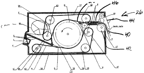
The stacking and dispensing device 26 receives
banknotes through the feed slot 40 and stacks the received
banknotes on the accumulator 56. The accumulator 56 is
preferably cylindrical and has a series of slots along in
the surface thereof. This defines an outer peripheral
surface 58 and an inner peripheral surface 60. The
banknotes are stacked against the outer peripheral surface
58 as shown in figure 5. The accumulator 56 is driven by a
first drive belt 48 which engages only a portion of the
accumulator and a second drive belt 50. The first and
second drive belts contact the outer most banknote and the
stacked banknotes effectively drive the accumulator 56.
The accumulator 56 is responsive to the speed of
the drive belts. With this arrangement the rotational
speed of the accumulator varies relative to the speed of
the drive belt and the tangential speed of the last
banknote is equal to the linear speed of the drive belts.
The banknotes are stacked one atop the other with the
leading edges 73 of the stack of banknotes 72 aligned and
in this case the trailing edges 75 of the banknotes are
also aligned as the banknotes are of a common length. This
length is less than the periphery of the accumulator 56
such that there is a substantial gap 80 between the leading
edges 73 and the trailing edges 75 of the stacked
banknotes.
The feed banknote 74 of figure 5 is about to
enter the stacking and dispensing device 26 as the toggle
member 44 has been moved outwardly to guide the leading
edge of the feed banknote 74 into the feed channel 46 of
the device. The transport feed drive 24 which is typically
- 6 -
CA 02299747 2000-03-02
WH-10,776CA
a belt drive or rollers causes the banknote 74 to move.
The speed of this transport is coordinated with the
variable speed of the drive belts such that the leading
edge of the feed banknote aligns with the leading edges 73
of the stacked banknotes 72. Various arrangements
including sensors and processing electronics can be used to
achieve the necessary synchronization between the drive
speeds. Banknotes stored on the accumulators 28 and 30 are
individually fed to the stacking and dispensing device 26
for initial stacking one atop the other as shown in figure
5. In this way a stack of banknotes is accumulated on the
accumulator 56. The accumulator 56 is continuously driven
by the belts and the belt speed is synchronized with the
speed of the transport 24 to achieve the necessary
alignment of banknotes. This continuous type of motion of
the accumulator, although not constant motion allows fast
processing relative to a stop/start motion for accumulation
of banknotes used in prior art devices.
Once the desired number of banknotes are
partially trained about accumulator 58, a discharge toggle
64 is moved to the position of figure 6. It can be seen
that the fingers 66 of the discharge toggle are received in
the slots of the accumulator and as such provide a
transition from the accumulator to the discharge port 68.
Once the desired number of banknotes have been
stacked on the accumulator the direction of the accumulator
is reversed and the toggle 64 is moved to the position of
figure 6. The fingers 66 are located in the gap 80 and the
rotational direction of the accumulator is reversed. The
second drive belt 50 continues to partially engage the
stacked banknotes 62 and the stacked banknotes are stripped
from the accumulator and dispensed as a group through the
discharge port 68. The second drive belt extends beyond
the accumulator 56 to drive the stacked banknotes through
the port 68. With this arrangement the trailing edges of
the banknotes are dispensed first.
_ 7 _
WH-10,776CA
CA 02299747 2000-03-02
The stacking and dispensing device 26 is rotated
in one direction for accumulation of banknotes and in a
second direction for dispensing of banknotes. As can be
appreciated from a review of figures 5 and 6 any attempt to
force the discharge toggle 64 to a dispensing position in
an attempt to withdraw bills fraudulently will have little
effect as the accumulator is rotating in a counterclockwise
direction and the stacked banknotes easily move past the
toggle. If desired the fingers 66 can be of a resilient
material and are easily caromed outwardly such that the
stacked banknotes to continue their movement. Therefore
the position of the toggle 68 does not determine whether
the banknotes will be dispensed. It is the position of the
toggle in combination with the direction of rotation of the
accumulator that determines whether stacked banknotes will
be discharged.
In the arrangement shown in figures 4 through 6 a
mechanical cam 81 is controlled and determines the position
of the discharge toggle 64. Other arrangements are
possible however a strong mechanical position control is
preferred such that movement of the discharge toggle by
engaging the blocking member 83 is strongly opposed.
The stacking and dispensing device of figures 4
through 6 coordinates with the drive transport 24 of the
overall device to achieve stacking of the banknotes one
atop the other. The partial training of the banknotes
about the periphery of the accumulator provides a gap where
the surface of the accumulator is exposed and this gap is
advantageously used to engage the accumulator at a point
beneath the stacked banknotes to assure full dispensing of
any stacked notes through the discharge port when the
device is operated in a discharge mode.
The operation of the device has been described with
respect to banknotes of a certain length all of which are
g _
CA 02299747 2000-03-02
WH-10,776CA
equal, however this need not be the case. The accumulator
is sized to receive the longest banknote with the banknote
only partially wrapped about the accumulator. However,
this can be used in combination with shorter length
banknotes. The banknotes can be aligned by leading or
trailing edges or any other form of alignment such that the
stack of banknotes on the accumulator defines the necessary
gap. The actual length of a received banknote can be known
from the validator which has conducted an evaluation of the
banknote.
The validator and dispensing unit of figures 2
and 3 has been shown with two accumulators 28 and 30.
However, additional accumulators can also be provided.
Similarly the drive transport arrangement 24 is shown as a
belt drive but other drive arrangements including
rotational rollers are also possible. The validator has
been described with respect to electronic circuitry for
maintaining in memory different information as well as
coordinating the speeds of the transport 24 and the
stacking and dispensing unit 26. Such electronic controls
and memory are shown as 21 in Figure 3.
The embodiment of figures 7 and 8 illustrate a
pivoting one belt arrangement for stacking of banknotes on
the accumulator and the dispensing of the stacked banknotes
through the discharge port. The modified banknote stacker
100 of figure 8 is positioned for receiving a banknote and
winding the banknote about the accumulator 102. The
accumulator is driven by belt 104 which also serves to trap
stacked banknotes between the belt and the accumulator.
The belt 104 is trained around end rollers 106 and 108
which are held in a fixed relative orientation by the V
shaped arm member 110. This arrangement is pivotable about
shaft 112. Banknotes are stacked on the accumulator in
manner similar to the stacker of Figures 4 and 5.
- 9 -
wH-10,776CA
CA 02299747 2000-03-02
The motor 120 controls the position of the V arm
arrangement and moves the rollers 106 and 108 to the
discharge position shown in Figure 7. This motor has also
caused movement of the discharge guide 122 to rotate
counter clockwise to align with the discharge port 124.
This action also brings fingers 126 of the discharge guide
into the slots provided on the accumulator. Motor 130 is
reversed in direction and drives the belt 104 to cause a
clockwise rotation of the accumulator. The stacked
banknotes 140 are dispensed as a stack after stripping from
the accumulator.
The rotary stacker is easily controlled to form a
stack of banknotes on the rotary accumulator which can be
stripped and dispensed as a stack through a discharge port.
The stacker is fast and reliable and is easily coordinated
with other devices such as temporary banknote accumulators.
Although various preferred embodiments of the
present invention have been described herein in detail, it
will be appreciated by those skilled in the art, that
variations may be made thereto without departing from the
spirit of the invention or the scope of the appended
claims.
- 10 -