Language selection

Search

Patent 2299784 Summary

Third-party information liability

Some of the information on this Web page has been provided by external sources. The Government of Canada is not responsible for the accuracy, reliability or currency of the information supplied by external sources. Users wishing to rely upon this information should consult directly with the source of the information. Content provided by external sources is not subject to official languages, privacy and accessibility requirements.

Claims and Abstract availability

Any discrepancies in the text and image of the Claims and Abstract are due to differing posting times. Text of the Claims and Abstract are posted:

  • At the time the application is open to public inspection;
  • At the time of issue of the patent (grant).
(12) Patent: (11) CA 2299784
(54) English Title: ROLLING MILL FINISHING SECTION
(54) French Title: SECTION DE FINITION DE LAMINOIR
Status: Deemed expired
Bibliographic Data
(51) International Patent Classification (IPC):
  • B21B 1/00 (2006.01)
  • B21B 1/18 (2006.01)
  • B21B 45/00 (2006.01)
  • B21B 15/00 (2006.01)
  • B21B 39/18 (2006.01)
  • B21B 45/02 (2006.01)
(72) Inventors :
  • SHORE, T. MICHAEL (United States of America)
(73) Owners :
  • SIEMENS INDUSTRY, INC. (United States of America)
(71) Applicants :
  • MORGAN CONSTRUCTION COMPANY (United States of America)
(74) Agent: FETHERSTONHAUGH & CO.
(74) Associate agent:
(45) Issued: 2004-06-29
(22) Filed Date: 2000-02-23
(41) Open to Public Inspection: 2000-09-11
Examination requested: 2000-02-23
Availability of licence: N/A
(25) Language of filing: English

Patent Cooperation Treaty (PCT): No

(30) Application Priority Data:
Application No. Country/Territory Date
60/123,873 United States of America 1999-03-11
09/495,224 United States of America 2000-01-31

Abstracts

English Abstract

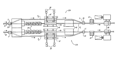
A method and apparatus for finish rolling long products such as bars, rods and the like, comprising: in a first operational mode, rolling the products through a finishing block and a reducing sizing mill arranged on a primary pass line; and in a second operational mode, diverting the products from the primary pass line to a secondary pass line bypassing the finishing block and then back to the primary pass line for rolling in the reducing sizing mill. Optionally and preferably, a cooling unit is shifted between the primary and secondary pass lines to cool products being rolled in each operational mode.


French Abstract

Procédé et appareil pour le laminage de finition de produits longs tels que des barres, des tiges ou autre, comprenant : selon un premier mode de fonctionnement, laminer les produits dans une cage de finition et un calibreur-réducteur disposé dans un ensemble de première passe; et selon un deuxième mode de fonctionnement, dévier les produits de l'ensemble de première passe vers un ensemble de deuxième passe, évitant la cage de finition, et ensuite retourner vers l'ensemble de première passe pour le laminage dans le calibreur-réducteur. Optionnellement et préférablement, une unité de refroidissement est intercalée entre les ensembles de première et seconde passe pour refroidir les produits laminés selon chaque mode de fonctionnement.

Claims

Note: Claims are shown in the official language in which they were submitted.


7
THE EMBODIMENTS OF THE INVENTION IN WHICH AN EXCLUSIVE
PROPERTY OR PRIVILEGE IS CLAIMED ARE DEFINED AS FOLLOWS.
1. A rolling mill finishing section for rolling long products such as bars and
rods, comprising:
a finishing block and a reducing sizing mill arranged sequentially along a
primary pass line;
a secondary pass line departing from said primary pass line at an upstream
junction preceding said finishing block, said secondary pass line bypassing
said
finishing block to rejoin said primary pass line at a downstream junction
preceding said
reducing sizing mill;
switch mechanisms at said junctions, said switch mechanisms being operable in
a first mode to direct products along said primary pass line for rolling in
both said
finishing block and said reducing sizing mill, and being operable in a second
mode to
direct products initially along said secondary pass line to bypass said
finishing block
and then to return said products to said primary pass line for rolling in said
reducing
sizing mill; and
a water cooling unit located between said upstream and downstream junctions,
and means for shifting said water cooling unit between said primary and
secondary pass
lines to cool products being rolled in each of said modes.
2. The rolling mill finishing section of claim 1 further comprising a cobble
and crop shear unit located on said primary pass line between said downstream
junction
and said reducing sizing mill.


8
3. The rolling mill finishing section of claim 1 further comprising a second
cooling unit on said primary rolling line at a location spaced from both said
first
mentioned water cooling unit and said downstream junction.
4. The rolling mill finishing section of claim 1 combined with a second
identical rolling mill finishing section, the said two finishing sections
being arranged as
mirror images of each other.
5. A method of finish rolling long products such as bars and rods,
comprising:
in a first operational mode, rolling said products through a finishing block
and a
reducing sizing mill arranged on a primary pass line;
in a second operational mode, diverting said products from said primary pass
line to a secondary pass line bypassing said finishing block and then back to
said
primary pass line for rolling in said reducing sizing mill; and
shifting a water cooling unit between said primary and secondary pass lines to
cool products being rolled in each of said operational modes.

Description

Note: Descriptions are shown in the official language in which they were submitted.


CA 02299784 2004-O1-12
2
ROLLING MILL FINISHING SECTION
BACKGROUND OF THE INVENTION
1. Field of the Invention
This invention relates generally to continuous rolling mills for rolling long
products such as bars, rods and the like, and is concerned in particular with
an
improved layout for the finishing section of such mills.
2. Descr~tion of the Prior Art
As shown for example in U.S. Patent No. 5,325,697 (Shore et al.), it is known
to
roll products sequentially in finishing blocks and post finishing blocks
(commonly
referred to as "reducing sizing mills") arranged along a common primary pass
line.
Although this practice has many advantages which have resulted in its
widespread
commercial acceptance, one disadvantage stems from the inability to continue
utilizing
the reducing sizing mill while the upstream finishing block is being serviced
or
reconfigured to roll different products.
SUMMARY OF THE INVENTION
Accordingly there is provided a rolling mill finishing section for rolling
long
products such as bars and rods, comprised of a finishing block and a reducing
sizing
mill arranged sequentially along a primary pass line. A secondary pass line
diverges
from the primary pass line at an upstream junction preceding the finishing
block, and
bypasses the finishing block, and then rejoins the primary pass line at a
downstream

CA 02299784 2004-O1-12
3
junction preceding the reducing sizing mill. Switches at the upstream and
downstream
junctions are operable in one mode to direct products exclusively along the
primary
pass line for sequential rolling in both the finishing block and the reducing
sizing mill.
Alternatively, when the finishing block is out of service for various reasons,
e.g., when
S dummying individual stands, for normal maintenance, etc., the switches may
be
operated to divert products along the secondary pass line and around the
finishing block
for rolling solely in the reducing sizing mill. At least one water cooling
unit is
provided which is shiftable between the primary and secondary rolling lines
for cooling
the products being directed to the reducing sizing mill in both of the
aforesaid operating
modes.
According to another aspect of the invention there is provided a method of
finish rolling long products such as bars and rods comprised of a first
operational mode
wherein the products are rolled through a finishing block and a reducing
sizing mill
arranged on a primary pass line. In a second operational mode the products are
diverted from the primary pass line to a secondary pass line bypassing the
finishing
block and then back to the primary pass line for rolling in the reducing
sizing mill. A
water cooling unit shifts between the primary and secondary pass lines to cool
products
being rolled in each of the operational modes.
BRIEF DESCRIPTION OF THE DRAWING
The accompanying drawing is a schematic plan view showing two rolling mill
finishing sections in accordance with the present invention, one being
arranged as a
mirror image of the other.

CA 02299784 2004-O1-12
4
DETAILED DESCRIPTION OF THE PREFERRED EMBODIMENT
Process sections that have already undergone rolling in upstream conventional
roughing and intermediate mill sections (not shown) are directed along two
parallel
delivery paths 10 to two rolling mill finishing sections 12A, 12B each being
arranged in
accordance with the present invention, with one being a mirror image of the
other.
Each finishing section includes a finishing block 14, water cooling units 16,
18
and a reducing sizing mill 20 arranged along a primary pass line P1 aligned
with a
respective one of the delivery paths 10. The finishing block 14 includes a
plurality of
mechanically interconnected roll stands driven by a common drive and
configured and
arranged to roll products in a twist-free manner. One such finishing block is
described
in U.S. Patent No. 5,577,405 (Shore et al.).
The reducing sizing mill 20 may be a so-called "post finishing block" as
described in U.S. Patent No. 5,325,697, where one or several light reduction
round
passes are preceded by a heavy reduction oval-round pass sequence, with the
time
interval between passes being sufficiently brief to avoid abnormal grain
growth in the
products being rolled.
Each finishing mill section 12A, 12B is further provided with a secondary pass
line PZ which departs from the primary pass line Pl at an upstream junction 22
preceding the finishing block 14, and rejoins the primary pass line at a
downstream
junction 24 preceding the reducing sizing mill 20. The intermediate portion of
each
secondary pass line P2 bypasses the respective adjacent finishing block 14.
Switch
mechanisms S located at the junctions 22, 24 are operable

CA 02299784 2000-02-23
D-1130
in a first mode to direct products along the primary pass lines P1 for rolling
in both the
finishing blocks 14 and the reducing sizing mills 20. In a second operational
mode, the
switches S are operable to divert products from the primary pass lines Pl to
the secondary pass
lines P2 in order to bypass the finishing blocks 14 before returning to the
primary pass lines for
rolling solely in the reducing sizing mills 20.
Optionally and preferably, the water cooling units 16 are shiftable laterally
along tracks
26 by any conventional means, e.g., piston-cylinder units 28. When positioned
on the primary
pass lines Pl, the water cooling units 16 are positioned to operate in concert
with the
downstream water cooling units 18 to cool the products emerging from the
finishing blocks 14
to before they are subjected to continued rolling in the reducing sizing mills
20. When shifted to
the positions indicated at 16 ~ , the water cooling units lie on the secondary
pass lines P2 where
they again operate to cool the products bypassing the finishing block before
they are rolled in
the reducing sizing mills.
Cobble and crop shear units 32 may be located between the downstream junctions
24
is and the reducing sizing mills 20. Products emerging from the reducing
sizing mills are
directed to conventional controlled cooling and handling systems (not shown).
With the above described layout, in one operational mode, products can be
rolled
sequentially in the finishing blocks 14 and reducing sizing mills 20. In
another operational
mode, when the finishing blocks are out of service, larger diameter products
can continue to be
2o rolled in the reducing sizing mills 20. In either case, if desired, lower
temperature
5

CA 02299784 2000-02-23
D-11.
theremomechanical rolling can be carried out in the reducing sizing mills by
proper
positioning the water cooling units 16.
6

Representative Drawing
A single figure which represents the drawing illustrating the invention.
Administrative Status

For a clearer understanding of the status of the application/patent presented on this page, the site Disclaimer , as well as the definitions for Patent , Administrative Status , Maintenance Fee  and Payment History  should be consulted.

Administrative Status

Title Date
Forecasted Issue Date 2004-06-29
(22) Filed 2000-02-23
Examination Requested 2000-02-23
(41) Open to Public Inspection 2000-09-11
(45) Issued 2004-06-29
Deemed Expired 2015-02-23

Abandonment History

There is no abandonment history.

Payment History

Fee Type Anniversary Year Due Date Amount Paid Paid Date
Request for Examination $400.00 2000-02-23
Registration of a document - section 124 $100.00 2000-02-23
Application Fee $300.00 2000-02-23
Maintenance Fee - Application - New Act 2 2002-02-25 $100.00 2002-02-05
Maintenance Fee - Application - New Act 3 2003-02-24 $100.00 2003-01-31
Maintenance Fee - Application - New Act 4 2004-02-23 $100.00 2003-11-07
Final Fee $300.00 2004-04-16
Maintenance Fee - Patent - New Act 5 2005-02-23 $200.00 2005-02-02
Maintenance Fee - Patent - New Act 6 2006-02-23 $200.00 2006-01-30
Maintenance Fee - Patent - New Act 7 2007-02-23 $200.00 2007-01-30
Maintenance Fee - Patent - New Act 8 2008-02-25 $200.00 2008-01-30
Maintenance Fee - Patent - New Act 9 2009-02-23 $200.00 2009-01-30
Maintenance Fee - Patent - New Act 10 2010-02-23 $250.00 2010-01-08
Registration of a document - section 124 $100.00 2010-07-13
Maintenance Fee - Patent - New Act 11 2011-02-23 $250.00 2011-01-19
Maintenance Fee - Patent - New Act 12 2012-02-23 $250.00 2012-01-10
Maintenance Fee - Patent - New Act 13 2013-02-25 $250.00 2013-01-17
Owners on Record

Note: Records showing the ownership history in alphabetical order.

Current Owners on Record
SIEMENS INDUSTRY, INC.
Past Owners on Record
MORGAN CONSTRUCTION COMPANY
SHORE, T. MICHAEL
Past Owners that do not appear in the "Owners on Record" listing will appear in other documentation within the application.
Documents

To view selected files, please enter reCAPTCHA code :


To view images, click a link in the Document Description column. To download the documents, select one or more checkboxes in the first column and then click the "Download Selected in PDF format (Zip Archive)" or the "Download Selected as Single PDF" button.

List of published and non-published patent-specific documents on the CPD .

If you have any difficulty accessing content, you can call the Client Service Centre at 1-866-997-1936 or send them an e-mail at CIPO Client Service Centre.


Document
Description 
Date
(yyyy-mm-dd) 
Number of pages   Size of Image (KB) 
Cover Page 2000-09-01 1 35
Description 2004-01-12 5 157
Claims 2004-01-12 2 58
Representative Drawing 2000-09-01 1 10
Drawings 2000-05-03 1 21
Abstract 2000-02-23 1 17
Description 2000-02-23 5 152
Claims 2000-02-23 2 65
Drawings 2000-02-23 1 23
Cover Page 2004-06-01 1 38
Prosecution-Amendment 2004-01-12 8 230
Assignment 2000-02-23 4 150
Prosecution-Amendment 2000-04-05 2 60
Prosecution-Amendment 2000-05-03 2 75
Prosecution-Amendment 2003-07-17 2 62
Correspondence 2004-04-16 1 29
Assignment 2010-07-13 11 330