Note: Descriptions are shown in the official language in which they were submitted.
CA 02299812 2000-03-O1
-1-
PHOTO-THERMAL TREATMENT DEVICE
Background and Summary of the Invention
The present invention relates generally to photo-thermal therapeutic
devices and more specifically to such a device which incorporates a plurality
of light
emitting diodes (LEDs) protruding from a specifically contoured housing with
the diode
spacing and curvature being designed to accommodate treatment of almost any
surface of the body for an exceedingly wide range of the population.
The use of light and heat to provide musculoskeletal pain relief,
promote cosmetic rejuvenation, promote accelerated healing of open and closed
wounds as well as numerous other benefits has long been known. However,
devices
for use in such treatments have in general been designed for specific
applications or
been relatively cumbersome to use.
The present invention, however, provides a uniquely designed device
for use in photo-thermal treatments which is compact and easy ;o use while
also
being contoured to enable it to adapt to most body contours for a wide range
of
individuals while still providing effective photo-thermal treatment. The
contoured
housing includes a plurality of LEDs arranged in spaced relationship along a
concave
surface with a single diode positioned at an outer convex surtace area so as
to enable
the device to treat both large general surface areas as well as specific
localized
areas. Additionally, the LEDs are preferably designed for sequential firing of
spaced
pairs of diodes preferably at a frequency in the range of 277 to 307 cycles
per second
so as to resist body adaptation to the treatment which adaptation may
significantly
and progressively reduce the effectiveness of the treatment over time.
CA 02299812 2000-03-O1
-2-
Additional advantages and features ofthe present invention will become
apparent from the subsequent description and the appended claims taken in
conjunction with the accompanying drawings.
Brief Description of the Drawin4s
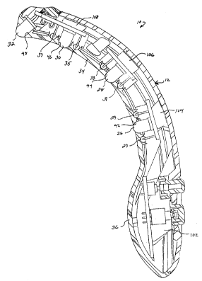
Figure 1 is an elevation view of the back side of the photo-thermal
treatment device shown connected to its remote power supply, all in accordance
with
the present invention;
Figure 2 is an elevational view of the device shown in Figure 1 as seen
from the front or treatment side;
Figure 3 is a sectional view of the device of Figure 2, the section being
taken along line 3-3 thereof; and
Figure 4 is an exploded perspective view of the device of Figure 2.
Description of the Preferred Embodiment
Referring now to the drawings and more specifically to Figures 1 and
2, there is shown a photo-thermal treatment device 10 in accordance with the
present
invention. Photo-thermal treatment device 10 includes a contoured housing 12
having
an actuation button 14 and a highllow button 16 generally centered on a lower
portion
of the back surface adjacent one end thereof, and a transparent indicator
light lens
18 positioned adjacent the opposite end thereof. Preferably buttons 14 and 16
will
be positioned within a slight recess 20 formed on the surface of housing 12 so
as to
inhibit the inadvertent operation thereof. A power cord 22 extends outwardly
from the
lower end of housing 12 and is removably connected to a remote power source 24
via a suitable connector. Power source 24 in tum is adapted to be connected to
a
CA 02299812 2000-03-O1
-3-
source of 120 volt 60 hz alternating current and to provide a suitable supply
of DC
current and voltage to treatment device 12.
As shown in Figure 2, the front or treatment side of housing 12 includes
four light emitting diodes 26, 28, 30, and 32 all of which are positioned in
spaced
relationship generally along a longitudinal midline of housing 12 with light
emitting
diode 32 being positioned closely adjacent the upper end of housing 12.
As best seen with reference to Figures 1 and 3, housing 12 is
preferably formed from a suitable polymeric composition and includes an
arcuate
upper treatment portion 34 within which light emitting diodes 26, 28, 30 and
32 are
positioned and a lower switch portion 36 of slightly increased lateral
thickness to
accommodate electronic circuitry therein. Preferably treatment portion 34 will
have
a radius of curvature approximating the average curvature of the top part of
the adult
human hand in the area of the knuckles,which curvature will also accommodate
the
average curvature of the wrist, arm and elbow of an adult human as well as
other
body areas of an adult human. Based upon research to date, it is believed that
a
radius of curvature of approximately 4.5" gives a treatment portion which is
extremely
well suited to enable the photo-thermal treatment device of the present
invention to
be effectively utilized to treat various portions of the human anatomy for
individuals
over a wide range of stature and build. More specifically, it has been found
that this
radius of curvature serves to easily and effectively accommodate treatment of
the
hand, wrist, arm, elbow as well as a variety of other portions of the body.
Housing 12 is designed to be easily formed such as by injection
molding or the like and includes inner and outer shell portions 38 and 40
which are
designed to be secured together in any suitable manner such as by fasteners or
adhesively joined telescoping posts for example. A plurality of openings 42,
44, 46
and 48 are provided positioned in spaced relationship generally along the
longitudinal
CA 02299812 2000-03-O1
-4-
midline of inner shell portion 38 with opening 48 being positioned closely
adjacent the
upper end thereof. Outer portion 40 also includes a pair of relatively closely
spaced
openings 50 and 52 opening into recess 20 which openings are adapted to
movably
receive respective buttons 14 and 16 and a third opening 54 positioned
adjacent the
opposite end thereof within which transparent lens 18 is fitted.
In order to augment the thermal treatment effects offered by diodes 26,
28, and 30, a plurality of resistors 27, 29, 31, 33, 35 and 37 are provided
being
positioned in pairs on opposite sides of respective diodes 26, 28, and 30.
Preferably
these resistors will be positioned with the heat generating resistive coil
portion in
contact with housing 34 immediately adjacent the respective diodes and will
operate
to transmit heat through the housing to elevate the skin temperature of a
subject
during the treatment process. It is contemplated that the augmentation of the
thermal
treatment effect of the diodes provided by the resistance elements will only
be utilized
when switch 16 of device 10 is in a high setting. Thus when switch 16 is in a
low
setting, there will be no current flow through resistors 27, 29, 31, 33, 35
and 37 and
both photo and thermal treatment effects will be provided by the diodes alone.
As previously noted, diodes 26, 28 and 30 are substantially equally
spaced along the longitudinal midline of housing 12. Preferably diodes 26, 28
and 30
are positioned so as to place the longitudinal axis thereof substantially
perpendicular
to the tangent of the radius of curvature with a spacing specifically designed
to
accommodate the average human anatomy. In a prefer-ed embodiment, the actual
longitudinal spacing between diodes 26, 28 and 30 is about one inch which
corresponds to the average distance between the knuckles of an adult human.
A singie diode 32 is also provided at the extreme end of housing 12
and is positioned with its axis forming an acute included angle of preferably
about 45°
with the tangent to the radius of curvature although angulations in the range
of from
CA 02299812 2000-03-O1
-5-
about 30° to about 60° may also be utilized. The primary purpose
in the positioning
and angulation of diode 32 is to provide_for localized point treatment of
areas of the
anatomy which may not be easily accessible to the multiple diode array
provided by
the main treatment portion such ~s for example superficial body orifices
(pares,
eyelids, lips and part of the auricle (ear) - posterior, conchs, helix,
tragus, auricular
insertion line on the face, lobule, superior hemi-conchs, and internal face),
point
treatment of the fingers and toes, and the many concave body areas that lie
between
tendon, cartilage, and bones, i.e. the area between the distal tip of the
fibula and the
Achilles tendon, the area between the distal tip of the tibia and Achilles
tendon, the
nose, the inner and outer area of the olecranon process of the elbow, the
tempera
mandibular joint (TMJ) among others.
Additionally, diode 32 may be utilized in a "point finder" mode in order
to assist in ascertaining specific treatment points. Use of diode 32 in a
"point finder'
mode results in a characteristic change in the arterial pulse known as
Vascular
Autonomic Signal.
Preferably light emitting diodes 26, 28, 30 and 32 will operate in the
infrared frequency range and in a preferred embodiment will emit light
frequency in
the range of about .6 to 1.5 micrometers. The use of such infrared light
emitting
diodes and the current flow through the resistors will enable the device to
apply
therapeutic thermal treatment as well as photo treatment by facilitating a
localized
increase in skin temperature. In order to control this localized skin
temperature
increase, the device of the present invention is provided with a switch
assembly 56
which enables selection of either a low or high heat range. In a preferred
embodiment, it is anticipated that the low setting will operate the diodes
only to
provide skin temperature elevation in a range from about 32.6° C. to
42.5° C. whereas
in a high setting, thermal treatment from the diodes will be augmented by heat
from
CA 02299812 2000-03-O1
-6-
the resistors. This added resistance heating will result in skin temperature
elevation
in the range of about 32.6° C. to about 48° C. The actual skin
temperature increases
in either setting will be dependent upon the duration of treatment, however,
it is
anticipated that both settings will result in the maximum temperature rise
being
achieved with a treatment duration of about 15 minutes under normal ambient
conditions.
As a result of the wave length of the light, and the frequency of
pulsation, and the energy delivery from the diodes (joules of energy from the
miliwattage of the diode) there results in the body a large number of
physiologic
responses. These physiological responses include for example acceleration of
the
production of procollagen resulting in enhanced collagen synthesis through
selective
action on collagen gene expression at the transcriptional level. This is a
likely sequel
to elevations of procollagen mRNA levels resulting in alterations in the
chromatin
structure. As a result of the increased collagen content and fibroblast cell
population,
photo-thermal treatment of device 10 produces a more rapid development of
increased wound tensile strength - almost 100% by the fourth post-traumatic
day
thereby decreasing the likelihood of wound dehiscence. There is increased
cross-
linking of existing collagen molecules and improved organization of functional
collagen
fibers. Also, photo-thermal treatment device 10 stimulates macrophages (a type
of
white blood cell) to release factors that stimulate fibroblast replication and
proliferation
(e.g. monokines). Cellular effects which occur include mitochondria)
hyperplasia, the
appearance of cytoplasmic microfilament bundles, and the deposition of an
abundant
fibrillar matrix in pericellular regions. A cellular phenotype of the
fibroblast, the
myofibroblast, is generated. This cell is found in granulation tissue; and its
primary
role occurs in the remodeling phase of wound healing, including contractile
activity in
CA 02299812 2000-03-O1
-7-
addition to the synthesis of collagen. The photothermal treatment device 10
thereby
accelerates the formation of a functional scar.
Energy delivered by photo-thermal treatment device 10 is absorbed at
the mitochondria) level and is available for photochemical rea~;tions which
leads to an
increase in oxidative enzyme activities. Photon absorption by
cytochromes,which are
present in large numbers in mitochondria) crests, result in an enhancement of
protein
synthesis producing increased substance for wound repair.
Use of photo-thermal treatment device 10 also accelerates
epithelization across open wounds, which not only speeds the healing of the
wound;
but, also reduces the risk of secondary infection which would delay healing
time and
increase morbidity. Relief of the edema (swelling) allows approximation of the
epithelial edges of the wound and further promotes wound healing.
Including and in addition to the above there are multiple biologic targets
of photothermal treatment device 10 among which are: stimulation of ionic
movements
between intracellular and extracellular compartments, action on mitochondria
via
cytochrome oxidases, photoelectric action on cell membrane repolarization by a
respiratory chain intermediary of the cytochrome, a photochemical effect on
protein
synthesis, an increase in RNA synthesis, and an action by resonance on DNA.
Application of photothermal treatment device 10 to the surface of
painful soft tissue areas and open and closed wounds results in an increase in
serotonin production and other neurotransmitter substances. Serotonin is a
chemical
precursor to endorphins, enkephlines, and dinorphines and subsequently
increased
levels of these naturally occurring "morphine like" products circulate in the
body
resulting in a reduction in pain.
Application of photo-thermal treatment device 10 also produces a
relaxation of painful reflex muscle spasm by restoring normal muscle tissue
properties
CA 02299812 2000-03-O1
-$-
on a cellular level through adenosine triphosphate (ATP) formation and enzyme
activity. Relaxation of spastic muscles relieves the painful stimulation and
irritation
of A and C nerve fibers.
Additionally, application of photo-thermal treatment device 10
decreases sensory nerve conduction velocity which also contributes to pain
reduction.
Use of photo-them~al treatment device 10 appears to raise the perception
threshold
of sensory nerves which promotes a reduction in pain.
Further application of photo-thermal treatment device 10 to painful,
swollen, stiff, non-septic joints reduces the pain, swelling, and erythema,
and
improves joint mobility and strength. These favorable effects result from the
multiple
mechanisms described above including the release of neurotransmitters,
alternations
in blood flow, cellular changes, alterations in neuronal transmittal and
sensitivity,
alterations in enzymatic activity.
It should also be noted that adaptation of the body to the
photo-stimulation treatment results in degradation of the effectiveness
thereof over
even relatively brief periods of time. In order to reduce or minimize the
ability of the
body to adapt to such treatment and hence to maximize the effectiveness
thereof, the
present invention incorporates circuitry to sequentially pulse the light
emitting diodes
26, 28, 30 and 32. While pulsing the diodes on and off at a set frequency
lessens the
rate at which the body is able to adapt to and hence reduce the effectiveness
of the
treatment, even greater resistance to body adaptation may be achieved by
varying the
frequency at which each diode is pulsed. In a preferred embodiment, it is
anticipated
that pairs of diodes will be pulsed sequentially with the frequency of pulses
being in
the range of about 277 to 307 cycles per second. More specifically, in the
currently
preferred embodiment of the present invention, diodes 28 and 32 will be
energized
simultaneously followed by the simultaneous energizing of diodes 26 and 30 as
CA 02299812 2000-03-O1
_g_
diodes 28 and 32 are deenergized. This sequential firing or energization of
pairs of
diodes greatly reduces the body's adaptation to the treatment which, as noted
above,
decreases the effectiveness of same without the need for more complicated and
costly electronic circuitry.
It should be noted, however, that if desired more complex circuitry
could be provided to cyclically fire or energize and deenergize each diode in
a
particular sequence rather than as pairs or even in a random sequencing of the
firing
order. Further, if desired, the duty cycle or on time versus off time could
also be
varied either by specific control or in a random manner.
As noted above, the lower portion of housing 12 is of a somewhat
thicker dimension so as to accommodate switch assembly 56 and a power on/off
switch assembly 58 which is preferably of the push on, push off type whereas
switch
56 will preferably be a double pole type with push button switching between
each of
the poles. Actuator buttons 14 and 16 protrude through openings 52 and 50
provided
in housing 12 and are biased outwardly by the respective switches. Preferably,
both
switches 56 and 58 will be mounted on a single circuit board 60 so as to
facilitate
assembly of the device which circuit board will also contain the necessary
circuitry to
accomplish the sequential firing of the respective diodes as well as to
control the
on/off and high/low switching of the apparatus.
Similarly, each of the diodes 26, 28, and 30 are also mounted to a
separate circuit boards 62, 64, and 66 with circuit board 66 also containing a
pair of
low power indicator lights 68, 70 with light 68 indicating if the device is
operating in
the high or low temperature range and indicator light 70 indicating if the
device is
switched on. Diode 32 is also mounted on circuit board 66 and each of the
circuit
boards 62, 64, and 66 have pairs of resistors 27, 29; 31, 33; and 35, 37
mounted
thereon as well as appropriate circuitry for selectively supplying power
thereto as well
CA 02299812 2000-03-O1
-10-
as to the respective diodes. Lens 18 provided in housing 12 is positioned to
overlie
the indicator lights 68 and 70 so as to allow easy, convenient viewing of same
from
the back side of the device 10.
In order to securely mount circuit board 60 in housing 12, a pair of
spaced substantially parallel raised flanges 72 and 74 are integrally formed
in portion
38 in the thicker portion of housing 12. Each of these flanges included a
generally
flat support edge 76 extending longitudinally of the housing upon which
circuit board
60 is designed to be seated as well as a pair of raised tab portions 78 and 80
at
opposite the respective flanges. Circuit board 60 includes cut out comer
portions 82
at each of the four corners thereof which are adapted to receive respective
tab
portions 78 and 80 so as to inhibit relative lateral and longitudinal movement
between
circuit board 60 and housing portion 38. In like manner, housing portion 38
also
includes three additional pairs of integrally formed upstanding longitudinally
extending
laterally spaced flange portions 84, 86, 88, 90, 92 and 94 each of which
includes a
longitudinally extending supporting surface 96 upon which respective circuit
boards
62, 64 and 66 are adapted to be supported and a pair of upstanding tab
portions 98,
100 at opposite ends thereof. As with circuit board 60, each of circuit boards
62, 64
and 66 include cut out portions 101 at each of the four corners thereof which
cut out
portions are designed to receive respective tab portions 98 and 100 and to
cooperate
therewith to resist relative lateral and longitudinal movement between the
circuit
boards and housing portion 38.
In order to retain circuit boards 60, 62, 64 and 66 seat on respective
flange portions 72, 74, 84, 86, 88, 90, 92 and 94 when housing portions 38 and
40
are secured together, housing portion 40 has integrally formed therewith
suitably
positioned raised flange portions 102,104,106 and 108 which are adapted to
engage
the surface of respective circuit boards 60, 62, 64 and 66 so as to retain
them in
CA 02299812 2000-03-O1
-11-
assembled relationship with the respective flanges and tabs. It should be
noted that
diodes 26, 28 and 30 will preferably be positioned so as to protrude slightly
outwardly
from the housing so as to enable direct contact with the body surface being
treated.
As mentioned above, the photo-thermal treatment device is designed
to be used with a suitable external remote power supply such as for example a
model
CV-6500-2 manufactured by Chi Stock which utilizes a 120 volt 60 hz input and
provides an output of 5.5 volts DC at 500 ma. Of course, any other suitable
power
supply may be used in place thereof. The circuitry required for sequentially
energizing each of the pairs of diodes will preferably be incorporated into
the switch
carrying circuit board, it being understood that the specific circuitry is
well known in
the art and hence not described in detail herein.
Referring once again to Figures 1 and 2, it is noted that the
photo-thermal treatment device of the present invention is specifically
ergonomically
shaped to promote ease of use as well as to adapt it for use in treating a
wide variety
of body surface portions. To this end, the upper treatment portion is not only
accurately shaped as noted above but also tapers to the upper end thereof
further
enhancing the ability of the point diode 32 to be used in treatment of
difficult to reach
localized areas. The enlarged lower portion of the housing facilitates hand
grasping
and holding of the device during treatment.
While it will be apparent that the preferred embodiment of the invention
disclosed is well calculated to provide the advantages and features above
stated, it
will be appreciated that the invention is susceptible to modification,
variation and
change without departing from the proper scope or fair meaning of the
subjoined
claims.