Note: Descriptions are shown in the official language in which they were submitted.
CA 02299818 2000-02-23
CANTILEVER JET DRIVE PACKAGE
BACKGROUND OF THE INVENTION
1. FIELD OF THE INVENTION
The present invention relates to a marine vessel having a water jet propulsion
system, and more particularly, to such a system having a drive engine
cantileverly
supported by the transom and wherein the water inlet passage or tunnel is
molded into
the hull of the boat with a water turbine aft of the boat transom.
DL: 1024159v1
093285-420538
CA 02299818 2000-02-23
2
2. DESCRIPTION OF RELATED ART INCLUDING INFORMATION
DISCLOSED UNDER 37 CFR 1.97 AND 1.98
Marine vessels driven by a water jet are not new. Neither is cantileverly
supporting an engine on the transom of the stern of a boat is not new. For
example,
U.S. Patent No. 3,259,099, issued to E.C. Kiekhaefer on July 5, 1966, shows an
inboard engine supported on a plate assembly which is cantileverly supported
by the
transom of the boat. The engine drive shaft passes through the transom to a
propeller
drive unit which drive unit can be rotated in a horizontal plane to provide
steering of
the boat.
Likewise, U.S. Patent No. 3,834,344, issued to Takao Yoshino on September
10, 1974, also shows an engine cantileverly mounted to a boat transom. A
rather
substantial size, circular hole is provided through the transom for controls
and the
engine drive shaft which runs to the boat propeller. The patent also discloses
rubber
mounting members for absorbing engine vibrations.
Also, U.S. Patent No. 3,583,357, issued to William J. Shimanckas on June 8,
1971, and assigned to the same assignee as the present invention, shows an
engine and
drive system combination mounted to the transom with a large hole therein for
passage
of the propeller drive unit and controls.
Another U.S. Patent No. 3,083,679, issued to W.C. Conover on April 2, 1963,
shows the engine cantileverly mounted to stern support members which are
adjacent
the transom. The engine drive shaft passes through a hole in the transom to a
propeller drive unit.
U.S. Patent 3,929,089, issued to Ralph E. Lambrecht et al., and also assigned
to the same assignee as the present invention, shows an engine which is
partially
supported in a cantileverly fashion by the transom, but also includes engine
mounts
attached to the bottom hull of the boat. A large hole defined in the transom
provides
a passage for the engine drive shaft.
DL: 1024159v1
093285-420538
CA 02299818 2000-02-23
3
U.S. Patent 2,064,463, issued to P. Crosley, Jr., on December 15, 1936, shows
a boat having a metal hull including a metal bottom portion and a stern wall.
A large
hole is defined by the stern wall portion in the rearwardmost bottom portion.
An
engine mount covers the hole in the stern and bottom and includes a top
portion for
passage of a rudder control. The engine mount also includes a portion on which
the
engine is cantileverly mounted and which defines a passageway for the drive
shaft
which connects to the boat's propeller.
DL: 1024159x1
093285-420538
CA 02299818 2000-02-23
4
SUMMARY OF THE INVENTION
It is an object of the present invention to provide an e$icient jet propulsion
drive
system for marine vessels.
Accordingly, the present invention discloses a marine vessel and jet
propulsion
system which comprises a vessel hull having a stern portion wherein the stern
portion
includes a transom member with inboard and aft faces. The stern portion also
defines
a water inlet passage or tunnel which in a preferred embodiment is molded into
the
boat hull. The transom defines a passage for providing a fluid connection from
the
water inlet housing to the aft face of the transom. The drive engine is
cantileverly
supported at the inboard face of the transom and the drive engine has a
rearward
portion and a forward portion with a power output. In a preferred embodiment,
a
drive plate assembly is connected to the power output shaft at the forward
portion of
the drive engine and in turn has a drive output below the engine. A turbojet
pump
assembly is in fluid connection with the transom passage and the water inlet
tunnel and
is mounted to the aft face of the transom at a location below the engine. A
drive shaft
connected to the turbojet pump extends between the turbojet pump and the drive
output of.the engine. The system further includes a mounting adaptor which is
mounted to the inboard face of the transom and also to the rearward portion of
the
drive engine to provide proper spacing and support to the engine. In a
preferred
embodiment, the mounting adaptor is constructed so as to act as the exhaust
manifold
housing. Also included in the transom are rubber isolation mounts between the
mounting adaptor bolts and the transom.
DL: 10241S9v1
093285-420538
CA 02299818 2000-02-23
BRIEF DESCRIPTION OF THE DRAWING
These and other features of the present invention will be more fully disclosed
when taken in conjunction with the following Detailed Description of the
Preferred
Embodiments) in which like numerals represent like elements and in which:
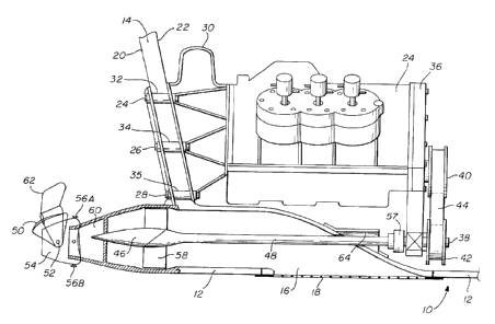
FIG. 1 is a plane view in partial cross section showing the water jet
5 propulsion system of the present invention cantileverly mounted to the
transom of the
marine vessel.
DL: 1024159x1
093285-420538
CA 02299818 2000-02-23
6
DETAILED DESCRT1'TION OF THE PREFERRED EMBODIMENTS)
Referring now to the single figure, there is shown in cross section a hull 10
of
a marine vessel having a bottom portion or hull 12 extending from the transom
portion
14 to a forward bow of the boat (not shown). The bottom of the hull 12 defines
a
water inlet passage or tunnel 16 which may be covered by a removable grating
or
screen 18. Removable grating 18 is to prevent debris from entering the water
passage
i6 and thereby avoiding damage to the turbojet drive. As shown, the bottom of
the
boat hull 12 is attached to transom 14 in a fluid-tight manner. Further as
shown,
transom 14 includes an aft face 20 and a forward or inboard face 22. As shown,
engine 24 may be any suitable power source such as a gasoline or diesel
internal
combustion engine. The engine also, of course, could be a 2-cycle or 4-cycle
engine
which has the necessary power for driving the boat. As shown, engine 24 is
cantileverly mounted to the inboard face of transom 14 at several locations by
bolts 24,
26, and 28. In a preferred embodiment, located between the engine 24 and
transom
14, is a mounting adaptor 30 which is preferably designed to have a shape so
as to
assure that engine 24 is maintained in a horizontal position. Further, in the
embodiment shown, the engine-mounting member 30 also serves as an exhaust
manifold.
To help prevent vibrations of the engine being transmitted to the boat, rubber
mounts 32, 34, and 36 are included in the transom such that the bolts 24, 26,
and 28
pass therethrough. Thus, it can be seen at this point, that the engine or
power source
24 is cantileverly mounted to the transom 14. As shown, at the forward end.of
engine
24, there is included a drive plate assembly 36 which receives the power
output of
engine 24. Drive plate assembly 36 extends below the bottom of the engine 24
as
shown and provides a power output 38 at a point below the engine. It will be
appreciated that the power output from engine 34 may be coupled to the power
output
3 8 by any suitable transmission technique, including a fixed ratio belt
drive, such as
DL: 1024159v1
093285-420538
CA 02299818 2000-02-23
7
indicated by pulleys 40 and 42 which are connected by belt 44. It will also be
appreciated by those skilled in the art that a fixed ratio gear drive could
readily be
substituted for the fixed ratio belt drive. Further, it is also possible to
use a changeable
ratio gear drive or a continuous variable transmission for transferring the
power from
the power output of the engine 24 to the power output 38. There may also be
included in any of the above-mentioned drive techniques an electric clutch
such that
the engine and transmission include a neutral setting.
Also as shown, there is included a jet pump and propeller unit 46 which is
cantileverly mounted to the aft face 20 of transom 14. A hole is defined in
the transom
14 at the bottom portion of the transom to allow passage for an elongated
drive shaft
48. Reverse gate 50 is shown as being pivotally mounted at pivot point 52 on
the
output nozzle 54. Controls (not shown) will also be included for activating
reverse
gate 50 and for pivotally rotating exhaust or thrust nozzle 54 at pivot points
56A and
56B.
Thus, in operation it would be appreciated that, when the engine 24 is
operating
and power is being transmitted to elongated drive shaft 48 from power output
38
through vibration damping coupler 57, water will be drawn into the tunnel area
or
passage 16, past screen 18 and is then exhausted under pressure by means of
propeller
blades 58 of the turbojet pump. The water is exhausted through the turbo
housing 60
into the steerable exhaust nozzle 54 such that it provides power to move the
boat. It
should be appreciated that reverse gate 50 also includes a rudder member 62 to
help
provide steering to the boat in addition to the rotating thrust nozzle.
Also as shown, there is a watertight seal member 64 for passage of the
elongated
drive shaft 48 through the hull of the boat.
In a preferred embodiment, the. water passage 16, defined in the hull of the
boat,
is molded at the time the boat is cast, such as by sand casting.
The corresponding structures, materials, acts, and equivalents of all means or
step plus fi~nction elements in the claims below are intended to include any
structure,
DL: 1024159v1
093285-420538
CA 02299818 2000-02-23
material, or act for performing the function in combination with other claimed
elements
as specifically claimed.
DL: 1024159v1
093285-420538