Note: Descriptions are shown in the official language in which they were submitted.
CA 02300014 2000-02-25
Attorney Docket:
37077/120
APPLICATION FOR CANADIAN LETTERS PATENT
TO ALL WHOM IT MAY CONCERN:
BE IT KNOWN THAT I, Melvin S. Mogil
of 86 Heddington Avenue, Toronto, Ontario MSN 2K8
Citizen of Canada, have invented a:
CONTAINER WITH INSULATED ENCLOSURE
of which the following is a specification.
20716147.5
CA 02300014 2000-02-25
CONTAINER WITH INSULATED ENCLOSURE
FIELD OF THE INVENTION
This invention relates to an integrated container that has an equipment
storage
compartment and a cooler.
BACKGROUND OF THE INVENTION
Carrying bags are used in many recreational activities. Typically, personal
use
carrying containers have a soft-sided body with handles, or a shoulder strap,
or both, for
ease of carrying. Carrying containers are of many types. They may be
characterized as
"equipment bags", or most commonly, as "gym bags" or "duffel bags". Larger
versions
of similar structure may tend to be termed "hockey bags". Although rigid
containers can
also be used, they tend to be less commonly used for carrying sports
equipment. Rigid
containers with large carrying volumes tend to be bulky, and may be difficult,
or
cumbersome. A rigid container may also tend to be heavy. A soft sided
container can be
flattened when not in use, and will tend to accommodate awkward shaped pieces
of sports
clothing, while also being suitably deformable for throwing in the irregular
storage space
of the trunk of a car, the footwell of a backseat of a car, or the rearward
part of a van or
station wagon.
Gym bags tend to have a number of desirable features. For example, they tend
to
be made of relatively light weight materials, so that they do not add
unreasonably to the
weight of objects to be carried. Further, inasmuch as they may be used to
carry
malodorous athletic clothing, they may tend to be made of a material that
breathes, or that
can itself be easily washed or aired. It is generally not desirable for the
body of a gym
bag to be made of a foamy or spongy material that may tend to absorb moisture,
as from
wet footwear or sweat, rain, or mud-soaked clothing, and whence it may be
difficult
adequately to rid pungent odours.
A gym bag, is distinct from a knapsack or a gunny sack. A knapsack is
generally
taller than broad or thick, and has a pair of straps on a leading portion to
permit the sack
to be carried on a wearer's back. A knapsack, when slung from one arm, may
tend to
drag on the ground, and, if carried high enough not to drag on the ground, may
be tiring.
A gunny sack tends also to be rather taller than wide or thick, and may tend
to have a
CA 02300014 2000-02-25
-2-
draw string at the top, the draw string also serving as a grab by which the
gunny sack can
be slung over one's shoulder. Access to objects at the bottom of the sack may
be
relatively poor.
A gym bag, by contrast, is designed to be carried in one hand. A gym bag is
typically longer than broad or deep, with aspect ratios of length to width in
the order of
2:1 being common. A size of roughly 20 - 24 inches (0. S to 0.6 m) in length,
by 10 - 12
inches ( 25 - 30 cm) in width, and 10 - 12 inches (25 -30 cm) in height would
be typical.
This is a size that makes for a convenient carry-on bag, such as might squeeze
to fit in the
overhead bin during a commuter airplane flight, or for storing in the overhead
rack of a
bus. A gym bag is not usually greater than about 3 ft (1.0 m) in length, as
beyond this
size the bag becomes less handy and more cumbersome.
A gym bag generally has handles mounted on opposite longitudinal sides, such
that a person can clasp both handles in one hand. When so grasped, the handles
tend to
be relatively close to the center of gravity of the bag (depending, of course,
on how it is
loaded). In use, when being carried in one hand by a user of average height, a
gym bag
tends to swing at about the level of the user's knee or calf, the handles
generally being too
short to permit the bag to drag on the ground and be scuffed. A gym bag does
not tend to
have back pack straps, since it is generally not intended to be carried over
great distances.
Rather, a gym bag is intended to be carried to an activity venue, such as a
sport field, and
carried back home again when the activity is finished.
The main compartment of a gym bag, frequently the only compartment, generally
has a closure member in the nature of a zipper, or a pair of parallel zippers,
running
longitudinally from end to end of the bag between the handles along the top
potion of the
bag. The bag is generally shallow enough to give good access to all parts of
the interior
when the zipper is open.
While gym bags are longer than tall, the cross-section of gym bags varies.
Smaller, older gym bags tend to have a round, or nearly round, cylindrical
shape with few
adornments. In more recent times gym bags have tended to be larger in section,
and to
tend to be more square or rectangular in shape. A third kind of gym bag is
often seen in
use for racquet sports, and has a base that is roughly rectangular, having an
aspect ratio of
3 S length to width of 1.5 : 1 to 2. 5: 1, and sides that taper somewhat
upwardly and inwardly.
Gym bags of this type tend to be somewhat taller than wide, and may have an
external
racquet pouch.
20716147.5
CA 02300014 2000-02-25
-3-
There are many occasions when it may be desirable to carry both perishable
food
items, such as fresh fruit, or cool drinks, simultaneously with a relatively
large volume of
other items, such sports clothing. While engaged in strenuous sporting
activity, such as
S soccer or other field sports, tennis or other racquet sports, or other
physical activity, a
person may tend to work up a good thirst. At a break in the game or match a
cool drink
may be preferred, rather than a tepid liquid that has been left too long in
the sun. Large
coolers for carrying beer for the entire team are well known, for example. It
has also
become common at sporting events, or vigorous physical activities, for
participants to
desire refreshment, whether merely drinks or also including foods, such as
sliced oranges.
A participant in a sport may not wish to carry separate containers, such as a
gym
bag for sports clothing and a portable cooler for refreshments. It may also be
undesirable
to carry refreshments, whether drinks or perishable foods such as fruit, in
the same
1 S container, whether insulated or otherwise, as basketball shoes; workout
clothing such as
socks, shorts and shorts; a basket ball, soccer ball, or football, and a
sandwich or drink for
later consumption. In the first instance a drink, or juicy piece of fruit, may
leak over the
sporting equipment. In the second instance, food carried with sports clothing
and athletic
shoes, and having spent a morning or afternoon in a sports locker, or the
trunk of a car,
may not acquire an overly palatable taste. In terms of keeping a cool drink
cool, or a hot
drink hot, it may be desirable to have an insulated, watertight container.
Further, the
transportation of perishable foods may call for the use of an insulated
container in the
interests of health and sanitation.
It may not be that only cooled beverages or snacks are desired. Bowls are
often
played well into the autumn. After an evening on the greens there may be a
chill in the
air, and tea or hot chocolate may be desired. In that light, an insulated
container, such as
a cooler, may also serve to keep items warm.
It would be advantageous to employ a single carrying container combining
spaces
for both sporting gear on the one hand, and insulated refreshments on the
other, and to
maintain a level of segregation between the spaces.
Heretofore, a typical solution has been to transport the items in two separate
containers: one insulated, the other not. Unfortunately this is usually a
cumbersome
arrangement which may require two hands rather than one. A single person may
not need
or desire an entire large cooler. There is a need for a personal carrying
container, such as
20716147.5
CA 02300014 2000-02-25
-4-
gym bag, that permits the carriage of sporting equipment while at the same
time permits
the carrying of drinks or foods that require or benefit from cooling, the two
items being
carried in a relatively convenient, and reasonably hygienic manner.
S SUN1NIARY OF THE INVENTION
In an aspect of the invention, there is a combination comprising a gym bag,
and a
cooler mounted to said gym bag.
In an additional feature of that aspect of the invention, the cooler has a
soft-shell
flexible insulated wall structure. The insulated wall structure defines an
insulated
chamber. In another additional feature, the insulated wall structure is
moveable to a
collapsed position, and has means for securing the insulated wall structure in
the
collapsed position. In a still further additional feature, the gym bag has an
uninsulated
1 S wall structure. In still another further additional feature, the gym bag
is moveable to a
collapsed position and has means for securing the gym bag in the collapsed
position.
In yet another additional feature of that aspect of the invention, the gym bag
is
moveable to a collapsed position and has means for securing the gym bag in the
collapsed
position thereof. The insulated cooler is moveable to a collapsed position and
has means
for securing the cooler in the collapsed position thereof. In still another
additional
feature, the gym bag has a pair of end walls and a sidewall extending between
the end
walls. The cooler is mounted to one of the end walls. In still yet another
additional
feature, the gym bag has a pair of end walls and a sidewall extending between
the end
walls. The cooler is mounted to the sidewall.
In another additional feature of that aspect of the invention, the cooler has
an
insulated soft-shell wall structure defining an insulated chamber. The cooler
has a
receptacle mounted to the soft-shell wall structure. The receptacle extends
inwardly of
the wall structure relative to the insulated chamber. The receptacle is
accessible from
outside the chamber. In yet another additional feature of that aspect of the
invention, a
covering is mounted to the cooler. The covering is movable to a position
overlying the
receptacle.
In another additional feature of that aspect of the invention, the gym bag has
a first
soft-shell wall structure having a longitudinal extent, namely a length, a
depth transverse
to the length, and a width transverse to both the length and the width. The
length is
20716147.5
CA 02300014 2000-02-25
-5-
greater than each of the depth and the width. The wall structure has a pair of
longitudinally spaced apart ends and a sidewall member extending therebetween
to define
a first enclosure. The first soft shell wall structure is moveable between a
collapsed
position and an expanded position. The sidewall member has a lower portion
upon which
the first soft-shell wall structure can rest, and an upper portion having a
closure member.
The closure member extends at least partially longitudinally, and is operable
to control
access to the first enclosure. The cooler has a second soft-shell wall
structure. The
second soft-shell wall structure has an insulating layer, and defines a second
enclosure
therewithin. The second enclosure is insulated. The cooler is movable to a
collapsed
position, and is securable in the collapsed position thereof. The cooler is
mounted to one
of the end walls of the gym bag.
In yet another feature of that aspect of the invention, the cooler has an
externally
accessible receptacle mounted thereto. The receptacle extends inwardly of the
insulated
1 S wall structure relative to the second enclosure. In still another feature,
the cooler has a
cover. The cover is movable to a position to overlie the receptacle. In a
further feature,
the first soft shell structure has a stiffened panel for placement adjacent
the lower portion
thereof inside the first enclosure. In yet a further feature, the stiffened
panel is foldable.
In still yet a further feature, the first enclosure and the second enclosure
share a common
wall. In still a further feature, the cooler has a watertight liner mounted
therein to
discourage migration of liquids contained in the cooler from the cooler to the
gym bag.
In yet a further feature of that aspect of the invention, the gym bag has a
first soft-
shell wall structure having a longitudinal extent, namely a length, a depth
transverse to
the length, and a width transverse to both the length and the width. The
length is greater
than each of the depth and the width. The wall structure has a pair of
longitudinally
spaced apart ends and a sidewall member extending therebetween to define a
first
enclosure. The first soft shell wall structure is moveable between a collapsed
position
and an expanded position. The sidewall member has a lower portion upon which
the first
soft-shell wall structure can rest, and an upper portion having a closure
member, and a
pair of spaced apart, opposed ascending portions intermediate lower and upper
portions.
The closure member extends at least partially longitudinally, and the closure
member is
operable to control access to the first enclosure. The cooler has a second
soft-shell wall
structure. The second soft-shell wall structure has an insulating layer, and
defines a
second enclosure therewithin. The second enclosure is insulated. The cooler is
movable
to a collapsed position, and is securable in the collapsed position thereof.
The cooler is
mounted to one of the ascending portions of the gym bag.
20716147.5
CA 02300014 2000-02-25
-6-
In another aspect of the invention, there is a flexible soft-sided container
assembly. The container assembly has a wall structure having a first portion
and a second
portion mounted thereto. The first portion has an uninsulated wall structure
defining a
S first chamber therewithin. The second portion has an insulated wall
structure defining a
second insulated chamber therewithin. The uninsulated wall structure has a
longitudinal
extent, namely a length, a vertical extent, namely a depth, and an extent
transverse to both
the length and depth, namely a width. The length is greater than each of the
depth and the
width. The uninsulated wall structure has a pair of longitudinally spaced end
walls, and a
sidewall extending therebetween. The insulated wall structure is mounted to
one of the
end walls.
In an additional feature of that aspect of the invention, the insulated
container has
a height, a width, and a depth. The depth of the uninsulated wall structure is
at least as
great as the height of the insulated container assembly. The width of the
uninsulated
container structure is at least as great as the width of the container
assembly. The depth
of the insulated container structure is less than each of the width and the
depth of the
insulated container structure.
Other aspects and features of the present invention will become apparent to
those
ordinarily skilled in the art upon review of the following description of the
preferred
embodiment of the invention in conjunction with the accompanying figures.
BRIEF DESCRIPTION OF THE DRAWINGS
Figure la is a general assembly isometric view of a container assembly;
Figure lb shows a top view of the container assembly of Figure la with a gym
bag and a cooler in extended positions;
Figure lc is a left hand side view of the container assembly of Figure la;
Figure ld is a right hand side view of the container assembly of Figure la;
Figure le is a view of an end of the container assembly of Figure la, being
the
cooler end face;
Figure if is a view of another end of the container assembly of Figure la,
being
the gym bag end face;
Figure lg is a bottom view of the container assembly of Figure la;
Figure 2a is a detail view of the container assembly of Figure la showing a
pouch
of the gym bag end in an open position;
20716147.5
CA 02300014 2000-02-25
_ 7 _
Figure 2b is a detail view of the container assembly of Figure la, showing a
lid of
the cooler in an open position;
Figure 2c shows a view of a.liner of the cooler of Figure la in an inverted
position;
Figure 2d is a scab view illustrating the wall construction of the cooler
portion of
the container assembly of Figure la;
Figure 3a shows an isometric view of the container assembly of Figure la in a
collapsed position;
Figure 3b shows a top view of container assembly 20 with a gym bag and a
cooler
in extended positions, the gym bag being partially open;
Figure 3c is a left hand side view of the container assembly of Figure 3a;
Figure 3d is a right hand side view of the container assembly of Figure 3a;
Figure 3e is a view of an end of the container assembly of Figure 3a, being
the
cooler end face;
Figure 3f is a bottom view of the container assembly of Figure 3a;
Figure 4a shows an isometric view of the container assembly of Figure la with
the cooler in a collapsed position and the gym bag in an extended position;
Figure 4b shows an isometric view of the container assembly of Figure la with
the cooler in an extended position and the gym bag in a collapsed position;
Figure 5a shows an alternate container assembly to the container assembly of
Figure la, having externally accessible receptacles mounted in the cooler;
Figure 5b is a cross-sectional view showing the wall construction of the
receptacles of Figure Sa;
Figure 6 shows an isometric view of an alternative embodiment of container
assembly to the container assembly of Figure la, having a side mounted
cooler;
Figure 7 shows an isometric view of an alternate embodiment to the container
assembly of Figure la with a gym bay of round cross-section;
Figure 8a shows an isometric view of a further alternative embodiment of
container assembly to the container assembly of Figure la; and
Figure 8b shows a reverse isometric view of the container assembly of Figure
8a.
DETAILED DESCRIPTION OF THE PREFERRED EMBODIMENT
The description that follows, and the embodiments described therein, are
provided
by way of illustration or example, or examples of particular embodiments of
the
principles of the present invention. These examples are provided for the
purposes of
20716147.5
CA 02300014 2000-02-25
_ g _
illustration, and not of limitation, of those principles and of the invention.
In the
description that follows, like parts are marked throughout the specification
and drawings
with the same respective reference numerals. The drawings are not necessarily
to scale
and in some instances proportions may have been exaggerated in order to more
clearly
depict certain features of the invention.
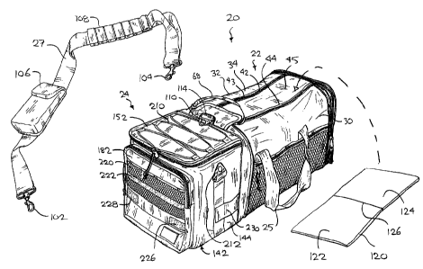
Generally, as shown in Figures la - lg, a soft-sided container assembly is
generally illustrated as 20. It has two sections: a general container section
in the nature of
an uninsulated, soft sided athletic or recreational activity bag of greater
length than height
or width, exemplified by a gym bag indicated as 22, and an insulated section,
in the
nature of a cooler 24. Gym bag 22 and cooler 24 are connected in such a manner
as to
make them easy to carry through the use of left and right hand carrying
handles 25, 26 or
a shoulder strap 27. In the preferred embodiment, gym bag 22 and cooler 24 are
each
independently collapsible, and can be secured in a respective collapsed
position. This
permits either section to be independently be collapsed while permitting use
of the other
section. Also, both cooler 24 and gym bag 22 can be collapsed at the same time
to
facilitate storage or transportation when not in use.
Considering the illustrations in greater detail, Figure la is a perspective
view of
container assembly 20 in a fully extended configuration, that is, in which gym
bag 22 and
cooler 24 are moved to respective fully extended positions. Figure lb shows a
top view
of container assembly 20 with the general container section, gym bag 22, open.
Gym bag
22 has a lower, or bottom portion, namely a generally rectangular floor 28, a
pair of left
and right hand ascending sidewall portions 30, 32 rising upwardly from floor
28, and an
upper or top portion 34 extending between the upper margins of sidewall
portions 30 and
32 above floor 28. Floor 28, sidewall portions 30, 32 and top portion 34
collectively form
a structure that, when moved to the extended position shown in Figure la, has
the form of
a cylinder of generally rectangular cross-section. The central axis of the
cylindrical
structure so formed, indicated as 35, is the longitudinal axis of container
assembly 20. A
common wall, or dividing wall, such as might be termed a partition, bulkhead
or panel 36
of generally rectangular plan form is located to one end of the rectangular
cylinder, and is
joined about its periphery to first longitudinal margins of floor 28, sidewall
portions 30,
32 and top portion 34, and thereby defines an end wall of gym bag 22. Another
end wall,
or bulkhead, indicated as end panel 38, of similar plan form to panel 36, is
joined about
its periphery to second, distal margins of floor 28, sidewall portions 30, 32
and top
portion 34, and thereby defines another end wall of gym bag 22.
20716147.5
CA 02300014 2000-02-25
-9-
Panels 36, 38 and floor 28, sidewall portions 30, 32 and top portion 34 co-
operate
to define a first space, storage chamber or cavity, indicated generally as 40.
Top portion
34 has a pair of verges that are, structurally, inward extensions of sidewalls
30, 32 that
lean inwardly from the upper regions of sidewalls portions 30, 32 toward each
other, and
S a closure member 42 running longitudinally along the inboard edge of the
verges between
the panels 36 and 38. Closure member 42 has a pair of parallel longitudinal
track
fasteners, in the nature of zippers, 43, 44 bounding a central flap 45.
Zippers 43 and 44
are operable to provide access, through an opening 50, to cavity 40. Floor 28,
side walls
30, 32 and end panels 36, 38 are all made from a lightweight, durable and
flexible water-
resistant or water-proof material, and are sewn together, although other
fastening methods
could also be used.
Opening 50 runs along the longest dimension of general container 54, being its
length. Opening 50 of cavity 40 is equal in dimension to the length of flap
45, whose
proximal end is sewn to the top of end wall panel 36. Flap 45 is flexible, and
easily
movable to provide access to cavity 40. The distal end 52 of flap 45 has an
hook-and-eye
connector strip 54 (typically made of Velcro (T.M.)), which mates with a
similar
connector strip (not shown) on a cover flap 56. Flap 56 is sewn to the top of
common
wall 36.
In Figure lc, when zippers 43 and 44 are in their closed position, flaps 45
and 56
fill the entire opening, namely opening 50. The two halves of zipper 43 are
sewn
respectively into the verges extending inward from sidewall 30, and the edge
of flap 45;
and the two halves of zipper 44 are sewn into the verge extending inwardly
from side wall
32 and the other side edge of flap 45. Tabs 64 and 66 of zippers 43 and 44,
respectively,
are connected by a thin strap 68, permitting zippers 43 and 44 to be easily
and
simultaneously operated.
Lifting, or carrying, members in the nature of handles 70 and 72 are attached
to
respective side wall portions 30 and 32, the handles being formed of strapping
secured at
either end and having a seamed bail 73. The strapping material of handles 70
and 72 is
carried fully under floor 28 and up the other side such that handles 70 and 72
are formed
from a continuous loop of webbing material. The bails of handles 70 and 72 can
be
clasped together in a single hand.
Gym bag 22 has peripheral skirts 74 and 76 that are mounted about the
periphery
of end panels 36 and 38 respectively, and which extend longitudinally inboard
therefrom.
20716147.5
CA 02300014 2000-02-25
- 10 -
The most inboard edges of skirts 74 and 76 carry respective halves of 78 and
79 of a
tracked closure member in the nature of a zipper 80, whose operation is
described more
fully below. Zipper halves 78, 79 extend around the circumference of container
side wall
30, floor 28 and side wall 32.
A pocket 82 is mounted to sidewall 30 and has an upper edge having a
longitudinal tracked closure member in the nature of zipper 84. Pocket 82 has
an open
mesh outer panel such that objects in pocket 82 can be seen, and so that
pocket 82 can
breathe. Other pocket panel materials could also be used.
At the distal end of gym bag 22, that is to say, at panel 38 distant from
cooler 24,
gym bag 22 has a flap 86 that is sewn about its bottom edge, and lower
portions of its side
edges to a thin peripheral wall 88 that extends outwardly from panel 38. The
remainder
of the periphery of flap 86 is releasably attached to panel 38 by a zipper 90
that runs
1 S along the remaining, upper portions of the side edges, and across the top
edge of flap 86.
Zipper 90 is operable to control access to the end pouch 87 thus formed. On
the outer
face of end panel 38, concealed by flap 86 when zipper 90 is closed, is an
internal pouch
92 having a divider member 93, an outer, screen-mesh pouch 94, pen holders 95,
and a
key holder 96 having a quick release spring catch.
Another lifting member is provided in the nature of long, rectangular strap 27
of
webbing material with releasable attachment fittings in the nature of clasps
102 and 104,
located at either end thereof. In the preferred embodiment, strap 100 has a
closable pouch
106 slidably attached to a medial portion thereof, and also has a plastic
shoulder brace
108 slidably attached thereto. Clasps 102 and 104 can be attached to lifting
members
mounted to the body of container assembly 20, namely lifting lugs, or eyelets
110 and
112, which are attached, respectively, to a sewn in web loop 114 mounted
centrally at the
top edge of panel 36, and to a distal web loop sewn to external flap 86. When
clasps 102
and 104 are attached to eyelets 110 and 112, carrying container assembly 20
can be
carried by strap 100.
A bottom panel liner in the nature of a floor board, is indicated in Figure la
as
120. It is made of a pair of stiff rectangular pieces 122, 124 of material,
overlain with a
fabric, and having a medial transverse hinge 126 to permit floor board 120 to
be folded.
Each of pieces 122, 124 is of a width slightly less than the width of end
panel 36 or 38,
and of a longitudinal extent less then the height of end wall panel 36 or 38,
such that,
when folded, floor board 120 can lie against, and within the peripheral
profile of, either
20716147.5
CA 02300014 2000-02-25
- 11 -
panel 36 or 38. Floor board 120 is inserted through opening 50 and placed to
lie on floor
panel 28, thus tending to provide a measure of rigidity, and puncture
resistance, to floor
28 of gym bag 22.
In the preferred embodiment, gym bag 22 is roughly 16 inches long (40 cm),
with
a height of roughly 10 inches (25 cm) and a width of roughly 10 inches (25
cm). The
corners of end panels 36 and 38 are radiused, and portions 28, 30, 32 and 34
conform to
the radiused profile so defined.
Cooler 24 will now be described in greater detail. Cooler 24 has a bottom
panel,
or floor 142; side walls 144 and 146 upstanding from floor 142 and
substantially in line
with side wall portions 30, 32 of gym bag 22; an end wall 148 distant from
wall panel 36,
also upstanding from floor 142 and meeting side walls 144 and 146 at common
vertices;
and wall panel 36 itself. Floor 142 , walls 144 and 146 and 148 and panel 36
define a
second storage chamber, or cavity 150. The upper margins, being top edges 162,
164,
and 166 of walls 144, 146, 148 and panel 36 define an opening 151 of cavity
150. A lid
152 is directly connected to panel 36 by a folded fabric hinge 153. A zipper
154
releasably connects lid 152 to the upper margins of side walls 144 and 146 and
end wall
148. When zipper 154 is unzipped, lid 152 can be folded back to permit entry
and exit of
objects from cooler 24. The inside surfaces of floor 142, side walls 144 and
146, end wall
148, common wall panel 36, and lid 152 forming the bounds of cavity 150 are
covered in
a shiny, reflective surface.
Top edges 162, 164 and 166 form the rim 168 of cavity 150. On the inside of
rim
168 is a liner securing means, or liner attachment mounting, in the nature of
a zipper 170,
which, in the embodiment illustrated, includes portions 171, 172 and 173
mounted
respectively to side walls 144 and 146, and end wall 148, and a hook-and-eye
fabric
fastener strip 176 mounted to common wall panel 36. Although this arrangement
is
preferred, in an alternative embodiment all of strip portions 171, 172, 173
and 176 (or
some other combination of them) could be hook-and-eye fasteners. Other types
of
mounting could be used, in addition to zippers, such as interlocking strip
seals, snaps,
clips, grommets or other means.
Figure 2d shows a cross section of end wall 148 with a liner 180 in place. A
scab
section of side wall 144 is also shown for the purpose of revealing its layers
of
construction. With the exception of auxiliary pouch 182, this section is
typical not only of
end wall 148 but also, more generally, of panel 36, side walls 144 and 146,
bottom panel
20716147.5
CA 02300014 2000-02-25
- 12 -
142 and lid 152. The outer facing layer of end wall 148 is a woven nylon
covering layer
184 for resisting abrasion. It overlays a closed cell foam insulation layer
186. The inner
face of insulation layer 186 is covered by a flexible plasticised reflective
sheeting 188.
Liner 180 seats inside sheeting 188, and, in use, is pressed against it by the
objects it
contains.
Liner 180 is made from a membrane, or web, preferably from flexible,
transparent
stock such as static cling vinyl, and as such, is impermeable to water or
other liquids such
as beverages, juice from fruit, leaking jam or peanut butter, and so on. Liner
180 has a
floor 190 and sides 192, 193, 194, and 195 extending upwardly from floor 190.
Each of
sides 192, 193, 194 and 195 is joined to floor 190 at a floor edge 196, 197,
198 and 199,
respectively, and each has an opposite or distal edge 200, 201, 202 and 203,
respectively,
distant from its respective floor edge. In this way a complete water-tight
lining is
provided for cavity 150.
Liner 180 has a peripheral lip 204 formed collectively by distal edges 200,
201,
202 and 203. Immediately below lip 204 are liner support fasteners, mounted to
some or
all of sides 192, 193, 194 and 195. This mounting may be by heat welding or by
use of a
bonding agent or adhesive. In the preferred embodiment lip 204 is folded over
to form a
hem, and fasteners 205, 206 and 207 are of the nature of a continuous zipper
around the
three sides of lip 204, and a fastener 208 in the nature of a fabric hook-and-
eye strip is
sewn in place at a height relative to floor 196 expected to be above the
likely liquid level
in liner 180. In an alternative embodiment, fasteners 205, 206 and 207 can all
be replaced
by fabric hook-and-eye fasteners each mounted on one side of lip 180, and
which mate
with corresponding fabric hook-and-eye fasteners mounted to walls 144, 146 and
148.
These fabric hook-and-eye fastener strips are commonly sold under the name
Velcro
(T.M.).
Figure 2b shows liner 180 removed from cooler section 24. Although liner 180
could be formed by heat-welding together floor 190 and sides 192, 193, 194 and
195, it is
preferable to construct liner 180 from a single integral sheet of material,
folded to a
watertight vessel as shown. This construction may tend to enhance durability
during
repeated foldings and un-foldings when cooler 24 is collapsed and expanded, as
described
below. It would also be desirable for liner 180 to be thin to better
facilitate collapsing
cooler 24. It would also be preferable for liner 178 to be transparent to
permit the shiny,
20716147.5
CA 02300014 2000-02-25
- 13 -
reflective surfaces of the inside surfaces of floor 142, side walls 144 and
146, end wall
148, panel 36, and lid 152 forming the bounds of cavity 150 to be seen.
Figure 2c is a perspective view of container 20 with liner 180 inverted, or
pulled
S out and its inside surfaces exposed, facilitating cleaning of liner 180
without removal
from container 20.
An elasticized retaining matrix 210 is located on top of lid 152, and permits
other
materials such as cups, plates, serving utensils or other objects to be
carried on top of
cooler 24. Eyelet 212 is located on side wall 144, and a similarly placed
eyelet 214 is
located on side wall 146. Eyelets 212 and 216 can connect with clasps 102 and
104 to
attach strap 100 as a convenient carrying strap when gym bag 22 is in a
collapsed
position.
Insulated pouch 182 has an external pocket 220, which may be made of mesh or
other material. A horizontal strip of fabric and hook-and-eye fastener 222 is
located on
pocket 220, and mates with a strip 224 located on the underside of lid 152
when cooler 24
is collapsed. Rectangular pieces of fabric hook-and-eye fastener 226 and 228
are located
on insulated pouch 182.
Securing straps 230 and 232 are attached to side walls 144 and 146 at their
junction with panel 36. Hook-and-eye strips 234, 236 are located on side walls
144 and
146, respectively to provide fastening points for mating hook-and-eye strips
at the distal
extremities of straps 230 and 232 when cooler 24 is in its extended position.
The use of hook-and-eye fasteners 226 and 228 when cooler 24 is collapsed is
illustrated in Figure 3a. End wall 148 is pushed toward common wall panel 36
with side
walls 144 and 146 being folded inward thus collapsing cavity 150. Zipper 154
is open,
and fastener strip 224 under lid 152 is mated with fastener strip 222. Straps
230 and 232
extend about cooler 24 to engage strips 226 and 228, thus securing cooler 24
in a
collapsed position.
When cooler 24 is fully collapsed and gym bag 22 is expanded as in Figure 4a,
container assembly 20 can be used as an equipment or gym bag, using the
general storage
space of gym bag 22. Container assembly 20 in this configuration can be
transported
using shoulder strap 100 attached to eyelets 110 and 112.
20716147.5
CA 02300014 2000-02-25
- 14 -
A top view of container assembly 20 with gym bag 22 collapsed and cooler 24
expanded is illustrated in Figure 4b. Floor board 120 is folded, and placed
flat against
common wall panel 36. End wall panel 38 is then pushed toward common wall
panel 36
(with floorboard 120 in-between). This can be accomplished with zippers 43 and
44
S open. Zipper 80 is then closed, enclosing handles 70 and 72. Zipper 80 thus
acts to
secure the gym bag 24 in a fully collapsed position. Flap 78 is typically
tucked in against
end wall 36, although this is not necessary. Note that in this configuration,
the container
20 may be used as a cooler carried by using strap 110.
A top view of container assembly 20 with both gym bag 22 and cooler 24
collapsed is illustrated in Figure 3a. In this fully collapsed configuration,
the container 20
takes up a reduced amount of space for storage or transportation.
A number of alternative embodiments are possible. Figure 5 shows a perspective
1 S view of an alternative embodiment of container assembly 250 with a gym bag
252 of
circular cylindrical shape. Gym bag 252 has a cooler 254 and a general gym bag
256.
Cooler 254 is similar to cooler 24, and notably has hook-and-eye strips 258
and 259
attached to end wall 260 of cooler 254. Hook-and-eye strip 258 mates with hook-
and-eye
strip 259 attached to a strap 262. There is also a hook-and-eye strip 264
which mates
with a hook-and-eye strip (not shown) on the inside of lid 268. Cooler 254 can
thus move
to a collapsed position, and can be retained, or secured, in the collapsed
position by using
hook-and-eye strips 258, 259, and 264 in a manner similar to cooler 24 of
container
assembly 20.
Gym bag 256 is similar to gym bag 24. The method of closure, while still
running
along the longest dimension of gym bag 256, consists of a zipper 258. Gym bag
256 is
made from a flexible, durable, moisture-resistant and breathable material, so
that it is
possible to collapse gym bag 256 in a manner similar to that of gym bag 24,
described
above. When collapsed, gym bag 256 is held in place by closing zipper 260.
Figure 5a shows an isometric view of a container assembly 280 having an
overall
parallelepiped shape. Container assembly 280 is substantially the same as
container
assembly 20 but also includes a cooler 282 having two externally accessible
receptacles
300, 302 for holding a beverage container. Container assembly 280 has cooler
282 and a
gym bag 284. Cooler 282 is similar to cooler section 24. Gym bag 284 is
similar to gym
bag 22 and is made from a flexible, durable, moisture-resistant and breathable
material, so
20716147.5
CA 02300014 2000-02-25
- 15 -
that it is possible to collapse gym bag 22 in a manner similar to that of gym
bag 22,
described above. When collapsed, gym bag 22 is held in place by a closing
zipper 288.
Cooler 282 has a hinged lid 290 having openings 304 formed therethrough. Lid
S 290 like the other walls of cooler 282, or cooler 24 has insulative
properties in that heat
transfer is retarded through lid 290. An example of a suitable lid in this
regard includes
an internal core of foam 306. Suitable foam polymers include ethylpropylene
ethylene
(EPE). A typical core will be about 8 mm thick. External to, or on opposite
sides thereof,
are an outer protective and decorative layer of polymer sheeting 308 and
another inner
protective layer of polymer sheeting 310. Layers 308 and 310 are preferably
made of a
material suitable for cleaning. A suitable material in this regard is nylon
(T.M.) sheeting.
Other suitable materials and combinations of materials may also be found.
Each externally accessible receptacle 300, 302 may take the general form
desired
for the particular end use. These include sleeves, pockets, cylinders and the
like. Each
such receptacle 300, 302 includes a mouth 312. In the illustrated embodiment,
mouth 312
conforms to the shape of opening 304 and has a perimeter size slightly less
than that of
the opening 304. Mouth 312 is selected to have a perimeter and size which
closely
approximates the external perimeter shape and size of the can, bottle, or the
like to be
held such as can 314. Each receptacle 300, 302 provides a downwardly depending
structure which accommodates at least a substantial portion of the volume of
the can,
bottle or the like. Preferably, the height of the receptacle is less than the
total height of
the can, bottle or like, to permit and facilitate access to the can, bottle or
like: that is, a
user can grasp and remove the can, bottle, or the like, from receptacle 300,
302 when
desired, such as in order to drink or pour from can 314.
The structure of receptacle 300, 302 is illustrated in the scab cross-section
of
Figure 5b. It includes a downwardly depending sidewall 316 which is generally
vertically oriented when container cooler 282 is in the upright position
illustrated in
Figure Sa. The illustrated receptacle 300, 302 further includes a bottom wall
318 upon
which can 314 or the like can rest. In the illustrated form, downwardly
depending
sidewall 316 has the configuration of a right cylinder, and the bottom wall
318 takes on
the shape of a disk. This shaping is suited for closely accommodating
illustrated can 314.
Receptacles 300, 302 are to be mounted integrally with lid 290 at openings
304.
Single-piece construction is possible in this regard, although often an
assembly can be
somewhat more convenient, particularly when the receptacle material is
different from
20716147.5
CA 02300014 2000-02-25
- 16 -
that of lid 290. As illustrated, a flange member 320 is used to join the
receptacle to lid
290. Illustrated flange member 320 includes a horizontal plate 322 which
overlies the
opening 304 and the adjacent edge of lid 290. A plurality of fastening devices
in the
nature of flexing fasteners 324 project from the horizontal plate 322 and into
and through
the lid 290. Horizontal backing plate 326 is included to enhance the security
of the
connection between fasteners 324 and lid 290. In this regard, the fasteners
324 pass
through respective openings provided in separate horizontal backing plate 326.
Fasteners
324 snap into place thereat.
Flange member 320 also includes a vertical annular leg 328 which depends
downwardly from horizontal plate 322. A cut-out or indent in the nature of a
shouldered
annular rabbet 330 is provided in receptacle sidewall 316 to accommodate the
thickness
and height of vertical annular leg 328. By either approach, the exposed
surface of the
vertical plate is flush with the inside surface of receptacle sidewall 316,
or, alternatively
1 S vertical annular leg 328 is slightly indented with respect to receptacle
sidewall 316. The
surface of receptacle 302 will thus engage the container when seated in
receptacle 302.
Another alternative embodiment of container assembly is shown in Figure 6. A
soft-sided container assembly 350 has a cooler 352 and a duffel, or gym bag
354. Gym
bag 354 is substantially similar in construction to the duffel bag, that is to
say gym bag
24, of Figure la. However, rather than having panel 36, which is insulated,
gym bag 354
has a second end panel 356 which is of the same construction as end panel 38,
thus
completing the boundary of the internal cavity of gym bag 365.
By contrast to container assembly 20, cooler 352 is mounted to a side wall
portion
360 of gym bag 354, in a saddle-bag like mounting, and has a rear insulated
panel, in
place of panel 36, that forms the rearward wall of cooler 352. The wall
construction of
cooler 352 is the same as cooler 22, but employs a greater width, oriented to
mount
lengthwise relative to sidewall portion 360, and lesser depth, extending
roughly from the
level of the floor of gym bag 24 to the base of handle 362. As shown, cooler
352 also
includes beverage container receptacles 364, 366 of the same form of
construction as
receptacles 300, 302 discussed above. Further, a cover, in the nature of a
flap 368
extends outwardly from the juncture of cooler 352 with sidewall portion 360.
Flap 368 is
positionable to cover containers seated in either of receptacles 364, 366 and
thereby to
tend to protect then from rain, or sun, and or wind.
20716147.5
CA 02300014 2000-02-25
- 17 -
Figure 7 shows a further alternative embodiment of container assembly 380,
that
differs from container assembly 20 by having a duffle bag, or gym bag, 382
that is of
substantially round cross-section, rather than the more square cross-sectional
configuration of gym bag 22. An insulated wall structure, namely cooler 384 is
mounted
to an end wall 386, of gym bag 382, and is of a size to fall within the
projected profile of
endwall 386. Although cooler 384 is box-shaped, having rectangular side wall,
lid, and
bottom wall panels, other shapes could be employed, and their profiles need
not
necessarily fall within the projected profile of the respective end wall of
the gym bag.
Further, a saddle-bag mounting along the side of a rounded gym bag could also
be made.
As shown in Figure 7, both gym bag 382 and cooler 384 are longitudinally
collapsible in
a manner similar to gym bag 22 and cooler 24. Cooler 384 is secured in the
collapsed
position by hook-and-eye fasteners, in the manner described above, and bag 382
is
secured in the collapsed position by circumferential zipper 388.
More generally, the shape of the container assembly need not be square, as
assembly 20, or round, as assembly 380, but could be oval, elliptical,
partially flat sided
(such as for a bottom face for resting on the floor), and partially arcuately
sided, or some
combination of flat and arcuate sides or large radius corners. A duffel bag or
gym bag
can have varying dimensions and proportions while still maintaining the
relationship of
having a major dimension, being the length, and minor dimensions for depth and
width
that are substantially less than the length.
Similar securement means is also provided to maintain the elements in their
collapsed positions to that of the container assembly 20. For each of the
collapsible
embodiments illustrated and described above, other types of securing means
could be
provided, whether a different arrangement of hook-and eye fasteners, the use
of snaps or
buttons, the use of zippers, or the use draw strings, or belts, or the use of
elasticized bands
such as bungee cords or the like.
A number of alternative configurations are possible, such as the addition of a
cover in the nature of flap 368 to cooler 282, or in the use of a cooler that
lacks beverage
receptacles, as in cooler 22, or in the nature of a container assembly having
coolers
mounted along either side, as in a double saddle-bag arrangement, or in having
coolers
such as cooler 24, or cooler 282, mounted to both ends of a gym bag similar to
gym bag
3 S 22 or gym bag 354.
20716147.5
CA 02300014 2000-02-25
- 18 -
A further alternative embodiment is shown in Figures 8a and 8b. A container
assembly 400 has a collapsible athletic gear bag 402 having a shape similar to
a small
valise or satchel, to which a collapsible insulated wall structure in the
nature of a cooler
404 is mounted in a side mounting. Athletic gear bag 402 has a lower, floor,
or bottom
panel 406, a top panel 408, and a pair of symmetrical end walls 410. Side wall
panels
414 and 416 extend upwardly from bottom panel 406, each having an upper
portion 418,
420, that is tapered inward (that is, toward each other). A pair of carrying
handles 422,
424 are mounted to upper portions 418 and 420, and have bails 426, 428 that
can be
drawn together and grasped by a single hand. Bag 402 has a longitudinal
tracked closure
member, in the nature of a zipper 430 that extends longitudinaly along the
center of top
panel 408, dividing it into two inwardly extending, co-operating verges 431,
433. Zipper
402 also extends partially down the end faces 410 such that when zipper 430 is
open,
upper portions 418, 420 can be spread outwardly somewhat to facititate access
to the
interior of bag 402. Bag 402 is of relatively soft-walled construction,
although, in an
alternative embodiment, side panels could be substantially rigid, or could
have a degree
of stiffening. Bag 402 is movable between collapsed and extended positions,
but, in
contrast to gym bag 22, gym bag 402 is collapsible in a direction
perpendicular to the
longitudinal direction. That is, athletic gear bag 402 is collapsible, or
expandible as the
case may be, in the width direction as indicated by arrow 'A', rather than in
the length
direction. As above, a means for securing bag 402 is provided, in the nature
of hook-and-
eye-strips 434, 435, 436 and straps 438.
Cooler 404 has a bottom panel 442, an outboard panel 444, left and right hand
side panels 446 and 448, and a hingedly connected top panel 440, with the same
general
construction as cooler 24 or 352, including a water proof liner similar in
construction to
liner 180. Beverage receptacles, such as receptacles 300, 302 could also be
installed in
the lid, namely top panel 440, in the manner shown in Figure 5a and 5b, above.
Cooler
404 is also collapsible in the direction of the width of bag 402, being
movable between
collapsed and extended positions, and has securing means, in the nature of
straps 441 and
hook-and-eye fasteners 443, 445 in an analogous manner to that described
above.
Container assembly 400 differs from container assembly 20 in having a
different
aspect of height to width, the height being greater than the width, typically
by 20 to 60 %.
For example, the width may be in the range of for example, about 8 - 10 inches
(20 - 25
cm) while the height is in the range of 10 or 12 to 16 inches (25 or 30 to 40
cm). The
aspect ratio of height to length may also be lower, the length being typically
18 to 24
inches (45 - 60 cm). As seen in the reverse view of container assembly 400,
such a
20716147.5
CA 02300014 2000-02-25
- 19 -
container assembly can also have, optionally, an external equipment mounting,
452. As
shown, external equipment mounting 452 is a racquet housing 454, such as would
be
suitable for racquet ball, tennis, badminton, or squash. A similar bag,
without a racquet
housing or mount, could be used for other sporting or recreational activities,
whether as a
collapsible picnic case, as a case for lawn bowls (with suitable internal
dividers) or bocce
balls. Alternatively, a second cooler, like cooler 404, can be mounted in
place of
equipment mounting 452. In this regard, while the term "cooler" has been used
above, it
is intended that the principles of the invention may apply to insulated wall
structures that
maintain warmth as well as those that maintain coolness.
A preferred embodiment has been described in detail and a number of
alternatives
have been considered. As changes in or additions to the above described
embodiments
may be made without departing from the nature, spirit or scope of the
invention, the
invention is not to be limited by or to those details.
20716147.5