Note: Descriptions are shown in the official language in which they were submitted.
CA 02300683 2005-08-08
i
75824-26
-1-
COILED TUBING DRILLING WITH SUPERCRITICAL CARBON
DIOXIDE
Field of the Invention
The present invention is generally directed to a method and apparatus for
drilling, and more specifically, to a method and apparatus for drilling that
uses
supercritical carbon dioxide (SC-COZ) as a drilling fluid.
Background of the Invention
After an oil or gas well has been successfully drilled and completed, it is
necessary over the productive lifetime of the well to perform maintenance
within
the well bore hole. This maintenance often includes de-scaling operations, or
reworking operations to increase production in older wells. It is quite
advantageous to be able to insert equipment into a bore hole to perform such
maintenance without removing the surface production equipment at the well
head.
Coiled tubing (CT) has been employed in the past for carrying out maintenance
procedures that do not require drilling and can be inserted into bore hole
through
the surface production equipment without removing the equipment.
More recently, CT has been used in conjunction with downhole motors for
drilling operations as well as other types of maintenance. Approximately 600
wells were drilled with CT rigs in 1997. In particular, CT drilling has become
an
_ accepted practice for creating lateral extensions from existing oil and gas
wells,
which are useful for increasing production levels in the wells.
CA 02300683 2000-03-14
-2-
While CT drilling equipment can be introduced into a bore hole through
existing surface production equipment and eliminates the labor and time
consuming steps of assembling and disassembling a traditional multi jointed
drillstring, CT drilliing has a limited ability to penetrate rock formations.
This
limitation exists because C'.T drillstrings have significantly lower thrust
and torque
capacities than do traditional jointed drillstrings.
The lower thrust is a result of limitations on the weight available to a CT
drillstring. A CT drillstring has a maximum weight capacity that is a function
of
the steel from which conventional CT is fabricated. Increasing the diameter of
a
~ 10 .CT can yield an increased weight capacity; however, the diameter can be
increased only up to the point at which the tube is so large as to be
difficult to coil,
or so large as to be unable to pass through the surface equipment at the well
head.
The torque capacity of a CT drillstring is also limited by the tubing
diameter.
These thrust and torque limitations consequently limit the rate of
penetration of bits at the c:nd of CT drillstrings. It is known that the
torque and
thrust required for ~~rilling under specific conditions can be greatly reduced
by
providing high pressure fluid jets at the drill head. Unfortunately, the
useful
service life of conventional steel CT is inversely proportional to the
operating
pressure. Conventional CT drilling operations are carried out at operating
pressures of under 35 MPa (.5,000 psi), to assure the service life of the
equipment
is sufficient to justify the equipment's initial capital expense. Such
pressures are
not sufficient: for water jet erosion of rock, which typically requires
pressures of at
least 15,000 psi. V~Jhile CT' drilling systems can be used with pressures up
to
15,000 psi, operation of a C'T drillstring at such pressures drastically
reduces the
service life of the; CT drillstring, making operations under such pressure
conditions impractical. Alternative CT materials such as titanium and
composite
may be used to increase pressure capacity, but these materials are
considerably
more expensive and are nat in common use.
Nevertheless, several CT-based drilling systems have been described in
the prior art. Despite the relatively poor penetration rate available with CT
drillstrings, the advantages noted above weigh heavily in favor of using such
equipment.
A CT system useful for drilling a lateral drainage well from within an
encased bore hole is described in U.S. Patent No. 5,413,184. A ball cutter is
coupled to the tubing and lowered into the bore hole. The ball cutter cuts
through
the bore hole casing, and a ;>hort distance into the strata beyond the casing.
The
ball cutter and tubing are wound back to the surface, and the ball cutter is
replaced
TEMP(NN)5-I-JR/INM15AF.Juc
CA 02300683 2000-03-14
-3-
with a nozzle blaster. The nozzle blaster is lowered into the bore hole and
moved
into the opening created by the ball cutter. Fluid is then pumped through the
nozzle blaster to cut through the stratum. As noted above, the range of
pressures
available with the use of C'T drillstrings do not provide a generally
satisfactory
penetration rate for ;such equipment.
Another CT-based system used to drill a lateral drainage well from within
an encased bore hole is described in U.S. Patent No. 5,944,123. A rotatable
drill
head including at least one fluid port is coupled to a distal end of the
tubing,
which is lowered into the bore hole. The rotatable drill head includes at
least one
contact member that is adapted to maintain a constant distance between the
drill
head and the substrate facie. Modulation of the rotation of the drill head
enables
drilling of an off-axis channel, which enables the resulting bore hole to have
a
radius of curvature much smaller than can be achieved with traditional
drillstrings.
Again, the range of pressures available with the use of CT drillstrings does
not
provide a generally satisfactory penetration rate, even though a bore hole
with a
desirable radius of curvature can be obtained.
It would therefore be desirable to provide a, method by which the
penetration rate of CT drillstrings can be increased, thus enabling the
benefits of
CT drilling operations to be realized without sacrificing performance with
respect
to the penetration rape of the drill head. It would further be desirable to
provide a
system that implements this method. The prior art does not disclose or suggest
such a method or apparatus.
Summary of the Invention
In accord with the present invention, a method is defined for using either a
supercritical fluid or a dense gas to increase an efficiency of a drilling
operation
performed with a drilling apparatus in a substrate. The method includes the
step
of providing a material that exists in either a supercritical phase state or a
dense
gas phase state at the temperature and pressure present in the substrate where
the
drilling operation occurs. A. fluid stream of the material is ejected within a
well,
and at least a portion of the material in the fluid stream exists in either
the
supercritical phase ;Mate or the dense gas phase state, increasing the
efficiency of
the drilling operation by providing cooling to the drilling apparatus,
removing
debris generated by the drilling operation, and/or eroding the substrate.
In one embodiment, the drilling apparatus includes a member adapted to
apply at least one of a mechanical cutting action, a mechanical grinding
action,
and a mechanical shearing action to the substrate. The member is positioned in
contact with the substrate.
TFMP(NNIS-I-)R/(NN)SAI'.Juc
CA 02300683 2000-03-14
-4-
In another embodiment, a fluid jet is included in the drilling apparatus,
which is positioned. adjacent to the substrate, such that the fluid jet is
directed
toward the substrate.
The pressure is preferably controlled at the drilling site to ensure that at
least the portion of the material exists in either the supercritical phase
state or the
dense gas phase st;~te at the drilling site. The material includes either
carbon
dioxide, methane, :natural gas, or a mixture of those materials. The drilling
operation includes removing scale deposits from a surface of the substrate,
forming an opening in the substrate, or enlarging an opening in the substrate.
. When the sc~bstrate includes a plurality of pores, the material is caused to
penetrate into the pores, which may be formed in a material such as rock or
concrete. In one application, the substrate is a well, and the material is
used for
recovering petroleum, natural gas, or other resources from a geological
formation.
The drill apparatus ohen preferably includes a coiled tube adapted to fit
within the
well. The coiled tube preferably includes a downhole motor and a drill head
driven by the downhole rnotor. The downhole motor can be a turbine motor, a
progressive cavity displacement motor, or a vane motor. The drill head can be
a
jet erosion bit, a me~~hanical bit, or a jet assisted mechanical bit.
In one form of the present invention, the downhole motor is energized by
causing the material to flow through the coiled tube and the downhole motor.
In
another form of the invention, a second fluid is provided, and the downhole
motor
is energized by causing the second material to flow through the coiled tube
and
the downhole motor.
The pressure at the; drill site can be controlled to ensure the material
exists
as a supercritical fluid or dense gas at the drill site. For example, if the
existing
well includes a surf~~ce choke manifold, the surface choke manifold can be
used to
control the pressure at the drill site. Alternately or in combination with the
surface choke manifold, the well can be capped with drilling mud to control
the
pressure at the drill site. Preferably, the pressure is caused to exceed 3.5
MPa, and
even more preferably, to exceed 7.4 MPa, when the material is carbon dioxide.
A recovery vessel can be used to collect and recover the material after it
has been used to increase the efficiency of the drilling operation, so that
the
material can be reused.
Another aspect of the present invention is directed to apparatus for using
either a supercritical fluid or dense gases in drilling operations. The
apparatus
- includes elements that carry out functions generally consistent with the
steps of
the method described above.
TEMP(NNIS-I-9R10(NISAI'.dac
CA 02300683 2005-08-08
75824-26
4a
According to an aspect of the present invention,
there is provided a method for using either a supercritical
fluid or a dense gas to increase an efficiency of a drilling
operation, comprising the steps of: (a) providing a
material that exists in one of a supercritical phase state
and a dense gas phase state at a temperature and a pressure
associated with a drill site where the drilling operation is
performed; (b) supplying the material to the drill site; (c)
exposing the material that is being supplied to a
temperature and a pressure that causes at least a portion of
the material being supplied to change its phase state to one
of a supercritical fluid and a dense gas; (d) ejecting a
fluid stream of said material being supplied onto said drill
site; and (e) performing said drilling operation, said
material that is ejected increasing an efficiency of said
drilling operation.
According to another aspect of the present
invention, there is provided a method for using either a
supercritical fluid or a dense gas to perform maintenance
within an existing bore hole formed by a drilling apparatus
within a substrate of a geological formation, comprising the
steps of: (a) providing a material that exists in one of a
supercritical phase state and a dense gas state at a
temperature and a pressure within the existing bore hole;
(b) ejecting a fluid stream of said material, said
temperature and pressure causing at least a portion of said
material in said fluid stream to exist in one of a
supercritical phase state and a dense gas phase state; and
(c) performing the maintenance in the existing bore hole
with said at least the portion of the material.
According to still another aspect of the present
invention, there is provided a system for using one of a
supercritical fluid and a dense gas to perform maintenance
CA 02300683 2005-08-08
75824-26
4b
related to an existing bore hole within a geological
formation, comprising: (a) a supply source for a material
that exists in one of a supercritical phase state and a
dense gas phase state at a temperature and a pressure found
within the existing bore hole; and (b) a drillstring having
a distal end and a proximal end, said distal end being in
fluid communication with said supply source, a tool defining
a fluid outlet being mounted on the proximal end, said
drillstring defining a fluid path from said supply source to
said fluid outlet, so that the material is supplied through
the fluid outlet at said one of supercritical phase and the
dense gas phase to perform maintenance in the existing bore
hole.
CA 02300683 2005-08-08
75824-26
-5~
Brief Description of the Drawing Figures
The foregoing aspects and many of the attendant advantages of this
invention will become more readily appreciated as the same becomes better
understood by reference to the following detailed description, when taken in
conjunction with the accompanying drawings, wherein:
FIGURE 1 is a phase diagram graph for carbon dioxide (COZ);
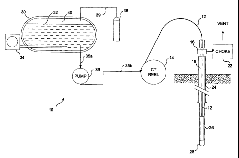
FIGURE 2 is a schematic view of SC-COZ being used in conjunction with
a coiled tube drilling operation;
FIGURE 3 is a schematic view of using mud cap drilling to control a
-pressure within a bore hole to drive SC-C02 into a petroleum formation to
increase production;
FIGURE 4 is a schematic view of a closed loop SC-C02 drilling method in
which spent CO~ is recovered for reuse;
FIGURE 5 is a schematic view of using a SC-COZ fluid jet to assist a
mechanical drilling operation;
FIGURE 6 is a schematic view of using a SC-CO~ fluid jet for erosion
drilling;
FIGURE 7 is a schematic view of using a SC-COZ fluid jet for de-scaling
tubing.; and
FIGURE 8 is a schematic view of SC-C02 being used
in conjunction with a second drilling fluid in a coiled tube
drilling operation.
Description of a Preferred Embodiment
Overview of the Present Invention
?c
The present invention employs supercritical fluids or dense gases in a
drilling operation. The unique properties of supercritical fluids and dense
gases
offer advantages that have not been applied heretofore in drilling bore holes
and in
other applications. A supercritical fluid is defined as any substance that is
above
its critical temperature (Tc), and critical pressure (Pc). Supercritical
fluids are
produced by heating a gas above its Tc, while compressing the gas above its
Pc;
or by compressing a liquid above its Pc, while heating the liquid above its
Tc.
The critical temperature is therefore the highest temperature at which a gas
can be
converted to a liquid by an increase in pressure. Similarly, the critical
pressure is
the highest pressure at which a liquid can be convened io a traditional gas by
an
increase in the liquid temperature. In the so-called critical region, there is
only
one phase of a substance, and the substance possesses properties of both a gas
and
' a liquid. Under these conditions, the molar volume of the substance is the
same
whether its original form was a liquid or a gas. A supercritical fluid
exhibits
physical-chemical properties intermediate between those of liquids and gases.
Mass transfer is rapid with supercritical fluids. Their dynamic viscosities
are
CA 02300683 2000-03-14
-6-
nearer to those in normal gaseous states. The diffusion coefficient is (in the
vicinity of the critical point) more than ten times that of a liquid.
In the following description and the claims that follow, it will be
understood that the term "supercritical fluid" means a substance that is above
its
critical temperature (Tc) and critical pressure (Pc), and thus exhibits
properties
intermediate between those of liquids and gases. The term "dense gas," as used
herein, should be understood to mean a gas whose pressure is within 25% of the
Pc for that gas and ~,vhose temperature is above the critical temperature Tc.
Thus,
an increase of up to 25% in the pressure of a dense gas will result in a
supercritical
fluid. Such a dense gas does not exhibit liquid-like properties to the extent
that a
supercritical fluid does, but dense gases do exhibit liquid-like properties to
a
useful extent. The term "drilling operation," as used herein and in the claims
that
follow, broadly means an operation in which a portion of a substrate is
removed.
That portion can represent a surface formation, such as scale deposits or high
points on a surface, or the portion of the substrate that is removed can form
a
cavity in the substrate, such as is the case when a hole is drilled in a
substrate.
It has been determine;d that the properties of supercritical fluids and dense
gases can be beneficially applied to drilling operations in a number of ways.
Supercritical fluids or dense; gases can be used as cutting fluids. The
viscosity
characteristics of supercritical fluids and dense gases can be exploited to
reduce
the load required to cut rock or rock-like materials, and to facilitate the
removal of
cuttings from a drill site. If the substrate is porous, jet erosion can occur
adjacent
to a drill head at lower fluid jet pressures than would be required if liquids
such as
water or fuel oil were employed. Jet erosion can be used alone to perform the
drilling operation, or to assist a mechanical drilling operation.
Because supercritical fluids and dense gases have specific temperature and
pressure requirements, the use of these materials in conjunction with a
drilling
operation reduires careful control of temperature and pressure conditions.
While
control of temperal:ure and pressure conditions can be readily achieved using
temperature controls and pressure vessels, it is preferable if temperature and
pressure conditions normally existing at the location of the drilling
operation
support the use of a supercritical fluid or dense gas with little modification
of
existing temperature; and pressure conditions.
The following disclosure of a preferred embodiment of the present invention
is applied to parteicular types of drilling operations regularly conducted in
association with extracting petroleum resources from a geological formation.
However, it is not intended that the invention be limited to this application,
since it
TFMP(NNIS-I-INI(NN~SAI'.J~m
CA 02300683 2000-03-14
_7_
can clearly be applvied to other types of drilling operations, and is not
limited to
drilling operations related to geological formations. By the use of
appropriate
temperature and pressure controls, supercritical fluids and dense gases can be
beneficially employed in conjunction with many other types of drilling
operations.
Details of a Preferrc;d Embodiment
The pressure and temperature conditions associated with drilling
operations related to extracting natural gas, petroleum and geothermal
resources
from within geologic formations are such that several readily available
materials
can be introduced into a drilling operation as supercritical fluids or dense
gases,
-without requiring complicated systems to control the temperature and pressure
at
the site of the drilling operation. 1n particular, carbon dioxide (COZ) can be
readily introduced ;~s a supercritical fluid or a dense gas into drilling
operations
associated with suclh geologic formations. It should be noted that while COZ
is a
particularly useful material, the present invention is not limited to only the
use of
COZ as the supercritical fluid or dense gas at the drill site.
It is well known that the temperature of geological formations increases
continuously with depth in the earth. The earth's temperature gradient is
typically
between 20 and 50 degrees centigrade per kilometer of depth. At depths below a
few hundred meters, the temperature of the earth is thus almost always greater
than 31 degrees centigrade - the critical temperature of carbon dioxide. While
COZ is a gas at pre~;sures and temperatures normally found on the earth's
surface
(though COZ can readily be compressed to form a liquid), under typical bore
hole
conditions, C'OZ exists as a supercritical fluid in the bore hole near the
bit. Under
these conditions, the SC-COZ is stable and effective for cooling drilling
equipment, removing cuttings, and eroding rock. The phase diagram for C02 is
shown in FIGURE I . At a temperature of 31 °C and pressure of 7.4 MPa
(about
1071 psi), COZ becomes a supercritical fluid. The viscosity of COZ at the
critical
point is only 0.02 c:entipoise, increasing with pressure to about 0.1
centipoise at
70 MPa (about 10,000 psi).
Liquid C02 is a dense fluid that is readily available and relatively easy to
handle. At temperatures below 31 ° C (300° K), and pressures
greater than
50 MPa, the density of liquidC02 is comparable to that of water. This fluid
can be
pumped using plunger pumps with relatively high efficiency, and can be used to
drive a turbine or positive displacement hydraulic motor. . Once inside a
geological formation, the ternperature and pressure conditions within the bore
hole
will cause liquid COZ to undergo a phase transformation into a supercritical
fluid
or a dense gas. This fluid can be used to drive a turbine or positive
displacement
T~MPINN15-I-yHIINN)SAP.Jm~
CA 02300683 2000-03-14
-g_
hydraulic motor so long as the density of the fluid is high. Thus, liquid COZ
can
easily be used as a replacement for water or water-based drilling fluids in
drilling
operations associated with petroleum resources. It is significant to note that
liquid
C02 and SC'-COZ are compatible with standard drilling equipment with minor
modifications to seals and plunger housings, and that specialized
drillstrings,
pumps, downhole motors and drill heads are not required.
When using SC-C'0;~ for drilling operations, the fluid will expand to the
ambient bottom hole pressure. If the ambient bottom hole pressure is kept
close to
or above the critical pressure (and such conditions are readily achievable
using
-conventional drilling techniques) the COZ will not flash to vapor, but will
form a
dense jet. Experiments have demonstrated that rock drilling in a SC-C02-filled
boreholeis much more efficient than drilling with water-based fluids.
Similarly,
jet erosion with SC-C02 jets is much more effective than jet erosion with
water
j ets.
In a first evmbodiment of the present invention, liquid COZ is used in
conjunction with a CT drillstring. FIGURE 2 illustrates such a SC-COZ CT
drilling system 10. In this system, liquid COZ 32 is used instead of water-
based
drilling fluids, or other types of drilling fluids. Liquid COZ 32 is provided
from a
C02 supply 30. Preferably., COZ supply 30 is a refrigerated bulk container. A
chiller 34 is used to maintain the temperature of liquid C02 32 to within a
range of
-20° C to 0° C. Unlike many other liquefied gases, such as
nitrogen, liquid CO~
is not characterized by c:xt:remely low, or cryogenic temperatures. Thus, the
pumps and fluid lines used for handling liquid COZ do not need to be able to
withstand extremely cold temperatures.
Typically, a liquid CO~ supply is stored under pressures ranging from 2 to
4 MPa. Preferably, COZ supply 30 is pressurized with a nitrogen blanket 40 to
keep liquid COZ 32 from vaporizing during transfer to a pump 36. The nitrogen
is
provided by a nitro;;en supply 38, connected to supply 30 via a fluid line 39.
The
use of a nitrogen blanket in conjunction with the pumping of liquid COZ is
well
known. Air can be; used instead of nitrogen. If a nitrogen or air blanket is
not
used, a super cooler can be used between liquid COZ supply 30 and pump 36, to
ensure that the liquid COZ does not vaporize, or flash, in the suction side of
the
pump causing a vapor-lock condition. The flashing refers to the liquid COZ
changing to a gas. When this change of state occurs at the pump, a vapor lock
may develop that c;an disrupt the pumping process. The use of a supercooler,
- rather than a nitrogen blanket, is less preferable, as it adds complexity to
the
system. Furthermore, supercooled liquid CO2, while not yet at cryogenic
TFMPIHNIS-I ~)N/INNISAP.ulnc
CA 02300683 2000-03-14
-9-
temperatures, does reduce the temperature at which the pumps and fluid
transfer
lines need to operate, which may increase failure rates. Thus, the use of a
nitrogen or air blanket is preferred.
Refrigerated COZ liduid 30 is fed to pump 36 through an insulated fluid
line 35a. Preferably pump :36 is a plunger type positive displacement pump
that
pressurizes the liquid CO;. to 10 to 20 MPa for mechanical drilling; or to
pressures
as high as 100 MPa for jet erosion drilling, or for jet erosion of carbonate
scale.
Once the liquid CC~Z leaves pump 36, it enters an insulated line 35b, which
leads
to a coiled tube 12 at a CT reel 14. It should be noted that while
supercritical fluid
drilling can be used in conjunction with more traditional multi jointed
drillstrings,
CT drillstrings are particularly well suited to SC-COZ drilling. In mufti
joint
drillstrings, pressure conditions within the drillstring change every time a
joint is
added to the drillstring. Liquid C'.OZ within the drillstring might flash to
gas and
be lost. While new liquid CO~ could be added to the drillstring after a joint
is
I S sealed, the proces~~ would not use liquid COZ very efficiently. Because CT
drillstrings are continuous, COZ is not lost as a drillstring is inserted into
a
formation.
Coiled tube 12 is advanced to the drilling site by inserting coiled tube 12
through a well head 16 into a cased bore hole 18. As the liquid COZ passes
through coiled tube 12 and into bore hole 18, its temperature will increase to
the
local ambient tempf~rature. Since bore hole temperatures are typically greater
than
31 ° C, the COZ will be in the: supercritical state as it reaches the
drill head or other
downhole tools. The SC-COZ can be used to drive a downhole motor 26, such as a
positive displacemf:nt type downhole motor, a turbine type motor or a rotary-
percussive hammer. Downhole motor 26 is used to energize a drill head 28.
Drill
head 28 preferably uses a jet erosion bit, a jet assisted mechanical bit, or a
conventional mechanical bit for rotary or rotary/percussive drilling.
The SC-CC>Z is compressible and will expand through nozzles (see
FIGURES 5-7) on drill head 28 to the ambient bore hole pressure. In a
preferred
embodiment of this invention, the pressure at the drilling site (generally the
hole
bottom) is maintained as close as possible to the critical pressure of 7.4
MPa, in
order to maintain the CO;~ in the bore hole in the dense gas or supercritical
state.
The drilling advantages achieved by the use of COZ are greatest when the
pressure
at the drilling site is equal to the critical pressure; however, substantial
drilling
advantages are obtained when the COZ is in the dense gas phase, or anywhere in
- the supercritical rel;ion at a temperature greater than 31 ° C or a
pressure greater
than 7.4 MPa.
TEMP(NNIS-I-9%/(NN)SAP.dnc
CA 02300683 2000-03-14
_ 10_
Once the COZ is ejected from drill head 28 and has enhanced the drilling
operation, the spent COZ will ascend up bore hole 18 to the surface and be
vented
to the atmosphere through a choke manifold 22. As the C02 ascends, it will
transport the drill cuttings to the surface as well. At the drilling site,
where the
COZ is in a supercritical state (or a dense gas state), the viscosity of the
C02 is
quite low, while its density is high. Consequently, the CO~ is quite turbulent
and
very effective at removing cuttings from the drill site and from horizontal or
highly inclined holes. As l:he COZ ascends to the surface, and changes in
state
from a supercriticall fluid or dense gas, the COZ's ability to transport
cuttings
diminishes somewhat as the density of the fluid diminishes. However, when
expanding from a dense l;as or supercritical fluid, the velocity of the C02
increases. Accordingly, the fluid's ability to transport cuttings remains
relatively
good and is increased if the diameter of bore hole 18 is small, as is the case
if bore
hole 18 is a production pipe; within a larger well. 1t should be noted that
C02 is
IS compatible with other types of drilling fluids, and it is envisioned that
water or
synthetic based drillling muds could be used in conjunction with CO2. It is
also
noted that, if a small amount of water containing foaming agents is injected
along
with the CO2, a foam will result when the COZ expands into a gas. This foam
will
assist in carrying cuttings from the upper, vertical portions of the hole.
It is possible to control bore hole pressure, to ensure that the COZ is a
supercritical fluid or a dense: gas at the drill site, by controlling the
pressure of the
C02 at the well head. 'Che upper portion of a bore hole is lined with a steel
casing 24 in order to prevent the escape of drilling fluids and production oil
or
gas. Casing 24 is capped with a well head 16 to control pressure. Well head 16
is
equipped with a port (not separately shown) that allows coiled tube 12 to be
introduced into bore hole; 18 while the well remains pressurized. Bore hole 18
pressure may be m;~intained by restricting the flow of drilling fluid from the
well
through choke manifold 22 located on well head 16 at the surface. In SC-COZ CT
drilling system 10 illustrated in FIGURE 2, the system is an open loop system,
and excess COZ is vented to the atmosphere through choke manifold 22.
In a preferred embodiment of this invention, choke manifold 22 includes a
plurality of individual choke valves (not separately shown) so that continuous
drilling operations are enabled even if one of the choke valves is being
serviced.
As the spent COZ alscends up bore hole 18 from the drilling site, its pressure
and
temperature may fall below the critical point. At this point, the COZ is a mix
of
vapor and liquid. A pressure gauge (not separately shown) located on the well
head can be used in conjunction with downhole temperature data to calculate
the
TGMP(NNIS-I-)NIINN)SAP.Jne
CA 02300683 2000-03-14
pressure in bore hole 18 using equation-of-state data for the density of CO2.
Those of ordinary skill in the art will readily understand the use of
equations-of-state ~to calculate the density of the COZ and consequently its
pressure within the borehole. Alternatively, a pressure gauge (not separately
shown) may be deployed near drill head 28 to enable direct monitoring of
downhole pressures without, resort to equation-of-state density calculations.
The
sensor for such a pressure gauge would be connected to a readout or display on
the surface through a cable that is disposed inside coiled tube 12. Such
pressure
monitoring techniques are. well known in the art.
~ Another method of controlling bore hole pressure to ensure that the COZ
exists in a supercritical or dense gas state at the drilling site is
illustrated in
FIGURE 3, in which a SC-COZ mudcap drilling system 50 is shown. In this
embodiment, C02 drilling occurs with a mudcap 52. Mudcap drilling is
commonly employed under conditions when bore hole 18 can accept the drilling
fluid and drill cuttings. Some bores holes or formations can be damaged by
disposing of drilling; fluids or cuttings within the well.
As described with respect to FIGURE 2, liquid C02 is pumped into coiled
tube 12, which is advanced to a desired drilling location within bore hole 18
via
well head lEi. Drilling mud, either water-based or synthetic mud, is pumped
into
bore hole 18 to prevent spent CO~ from ascending up the bore hole to the
surface,
which results in two phenomena. First, the pressure within the bore hole is
increased, generally ensuring that the pressure at the drill site is
sufficiently high
to enable the liquid COZ to transform into a supercritical phase state or a
dense gas
phase state.
The second phenomena relates to the diffusivity of SC-C02 and the
general porosity of geologic formations. Because the diffusivity of SC-C02 is
so
high, and the rock associated with petroleum containing formations is
generally
porous, the SC-CO~, is quite effective in penetrating the formation where
casing 24
does not line bore hole 18, as is illustrated by the arrows. This penetration
is
beneficial. COZ is commonly used to stimulate the production of oil wells,
because it tends to dissolve iin the oil, reducing the oil viscosity, while
providing a
pressure gradient that drives the oil from the formation. As illustrated in
FIGURE 3, the CT drillstring is being used to drill a lateral extension 53, a
technique commonly employed to increase the production in an existing well.
Because of mudcap 52, SC-COZ cannot ascend to the surface and vent through
choke manifold 22. Instead, SC-COZ fills a region 54 that includes lateral
extension 53 and tree balance of bore hole 18 below mudcap 52. Because of its
TEMPINHIS-I ~)R/IHNISAP.dnc
CA 02300683 2005-08-08
75824-26
-12-
extremely low viscosity and high density, SC-COz does an excellent job of
removing cuttings 58 from the newly drilled lateral extension 53. Mud cap 52
similarly prevents these cuttings from ascending through the surface. Instead,
the
SC-COZ carries cuttings 58 out of lateral extension 53 into the main bore hole
18,
where they settle and drop to the bottom of bore hole 18. When mudcap 52
causes the trapped CO~ to pressurize the bore hole above the pressure of
formation
fluids, the COZ is enabled to enter the formation. The spent C02 is thus used
to
energize the oil trapped in the formations, or to drive oil from one lateral
extension to another. This technique can also be used to generate
lateral drainage wells.
In cases where little benefit is expected from driving COZ into a formation,
ar ~nudcap drilling is not possible or desirable, it can economically and
environmentally beneficial to recover spent COZ ascending bore hole 18, rather
than venting the spent C02 to the atmosphere. Such a closed loop SC-C03
drilling system 60 is illustrated in FIGURE 4. Instead of being vented from
choke
manifold 22 as in the system illustrated in FIGURE 2, spent CO~ passes into a
fluid line 63a.
Fluid line 63a transfers the spent CO~, no longer a supercritical fluid but
primarily a gas, to a recovery vessel 64. Preferably, recovery vessel 64
operates at
2 to 5 MPa, which is the operating pressure of a typical pressure separator
vessel
employed in closed-loop underbalanced drilling. The flow into recovery vessel
64
may include water, solids, and COZ vapor. At an operating pressure of 2 to
5 MPa, the CO~ vaporizes, enabling the free water and solids to separate. The
volume of recovery vessel 64 preferably is sufficient to accommodate all of
the
solids and fluids produced during drilling. Such a recovery vessel is
practical
when drilling relatively short, small diameter bore holes. If a larger or
longer bore
hole is required, the separator may be equipped with solids removal equipment,
such as a pressurized auger. Those of ordinary skill in the art will readily
understand how such additional equipment can be incorporated into recovery
vessel 64 as illustrated.
Free CO~ gas exits recovery vessel 64 via a fluid line 63b to a filter
unit 66. The COa is filtered to remove any impurities that were not removed in
recovery vessel 64. After exiting filter unit 66, the filtered CO~ gas flows
through
a fluid line 63c to a compressor 68, which is used to compress the COZ to
around
5 MPa.
Upon exiting compressor 68, the CO~ will likely be in the gas or
supercritical state. The compressed C02 moves through a fluid line 63d to a
chiller 70, which is incorporated to transform the COZ into the liquid state
before
CA 02300683 2005-08-08
75824-26
-13=
it is pumped to higher pressures for drilling and jet erosion. The C02 exits
chiller 70 through an insulated fluid line 63e and flows to a valve 72. When
the
closed loop system is first started, valve 72 is used to direct liquid C02
from
liquid COZ supply 30 into pump 36, and through coiled tube 12 to the drill
site.
As spent COZ is recovered, valve 72 is used to enable recovered COZ to enter
pump 36, while simultaneously reducing the flow of liquid CO~ from supply 30
to
pump 36, to a level that makes up for any COz lost in the recovery process.
As noted above, once at the drill site, the SC-COz or dense gas COZ
enhances drilling operations in a number of ways. The very low viscosity/high
density fluid provides good transport of cuttings from the drill site, as well
as
' providing good cooling to the drill head. The high diffusivity of SC-COZ
(and to a
lesser extent, dense gas CO~), and the general porosity of rock formations
normally associated with petroleum deposits enables the CO~ to easily
penetrate
into the formation. This phenomenon is useful in both erosion drilling and
stimulating production by introducing CO~ into the formation (thinning the
petroleum, making recovery easier, as well as adding gas into the formation,
which further stimulates the production levels by driving more petroleum out
of
the formation). As the SC-CO~ flows through the CT, its density is sufficient
to
drive a downhole motor. The downhole motor comprises, for example, a turbine
motor, a progressive cavity displacement motor, a hydraulic vane motor, or a
rotary percussive hammer. FIGURES 5-7 illustrate three types of powered drill
heads that will be useful in SC-COZ CT drilling operations. While FIGURES 5-7
indicate that the SC-C02 flows through the CT and energizes
the downhole motor employed to rotate the drill heads, it is
envisioned that SC-COZ CT drilling systems could include a
dual conduit system, shown in FIGURE 8, in which a second
drilling fluid 32a, such as water, brine, or drill mud,
would flow from a separate supply vessel 30a through a fluid
line 35c to CT Reel 14. From CT Reel 14, second drilling
fluid 32 flows through a seprate conduit 12a in the CT to
power the downhole motor 26.
FIGURE 5 illustrates SC-CO~ flowing through coiled tube 12 being used
to improve the performance of a mechanical drill head. As described above, the
C02 will generally be in a liquid state when entering a well, and the
pressures and
temperatures within the well will cause the CO~ to change to the supercritical
phase state. The SC-COZ will energize downhole motor 26, which rotatingly
drives a mechanical drill head 28a. Mechanical drill head 28a can be one of
any
of the generally available mechanical drill heads normally used in the art.
Using
SC-CO~, downhole motor 26 can rotate a conventional rotary drill bit 7$ at a
torque and rotary speed comparable to that achieved when driven by the flow of
water or a water-based mud. Such conventional rotary bits include roller cone
CA 02300683 2005-08-08
75824-26
-14-
bits, surface-set or impregnated diamond bits, polycrystalline diamond compact
(PDC) bits, and thermally stabilized diamond (TSD) bits. The SC-C02 could also
drive a rotary-percussive hammer equipped with an appropriate bit.
The SC-COz would be directed through one or more conventional jet
nozzles located on the bit, or through an open flow passage, as on some bit
designs. Empirical data has demonstrated that SC-C02 provides substantially
_ better drilling rates than drilling with water-based muds, because SC-COZ
effectively eliminates differential pressures that commonly cause balling and
sticking of mechanical bits in pressurized bore holes.
. In a preferred embodiment, a plurality of SC-C02 fluid jets 74 are directed
at the rock face being drilled. In addition to removing cuttings from the
drill site
and' cooling the mechanical bit, fluid jets 74 also weaken the rock, thereby
aiding
in the drilling process. In this primarily mechanical drilling process, the SC-
C02
will be provided at pressures of up to 20 MPa.
The embodiment shown in FIGURE 5 may also employ SC-CO~ jets at
pressures of up to 100 MPa. In such an embodiment, fluid jets 74 greatly
reduce
the thrust and torque required for drilling by removing kerfs of rock and
leaving
behind thin ridges that are easily broken by drill bit 78. This technique is
also
well-known in the art of water jet drilling, and the same principles apply
when
using SC-CO~ as the fluid instead of water.
FIGURE 6 illustrates a drill head 28b that employs fluid jet erosion alone
for drilling purposes, rather a fluid jet in combination with a mechanical
bit. In
this embodiment, downhole motor 26a preferably incorporates a high-pressure
casing that transmits high-pressure SC-CO~ to the bit for jet erosion
drilling.
Multiple fluid jets 74 are distributed on drill head 28b in order to cut ttLe
entire
cross-sectional area of the hole. A non-rotating standoff collar 76
(also known as a non-rotating gagecullar) ensures that
drill head 28b will not advance until all of the rock ahead of the collar has
been
removed. While two fluid jets 74 are illustrated, those of ordinary skill in
the art
will readily understand that additional fluid jets may be used. Preferably one
fluid
jet will cross over the center of the hole to ensure that no rock remains
standing in
the center to obstruct the drill. This design is well known in water jet
drilling and
the same principles apply to COZ jet drilling.
While fluid jet drilling using water or drilling mud has been demonstrated
~5 in a wide variety of rock types, offering penetration with minimal thrust
or torque,
the efficiency and speed of the erosion of rock using water jets is very slow,
and
jet drilling systems have not achieved commercial success. Empirical data
obtained using a SC-C02 fluid jet demonstrates that SC-CO~ provides at least
an
CA 02300683 2000-03-14
-15-
order of magnitude improvement in the efficiency of jet erosion of hard rock.
This is due to the dramatically higher diffusivity that SC-COZ has in porous
materials. The pro~~ess of fluid jet erosion is greatly enhanced by the
diffusion of
the jetting fluid into micro cracks and pores in the rock, and because of its
much
higher diffusivity, SC-CO Z is a far superior jet erosion fluid than water. In
this
embodiment, the SC-CO~ is pumped through coiled tube 12 at pressures of 20 to
100 MPa. At these pressures, SC-COZ fluid jets 74 will erode rock and other
hard
materials.
In addition to using SC-COZ fluid jets to erode rock, the fluid jets can also
.be used to remove scale. Carbonate scale forms on the interior of the steel
casing
with a well, and th~~ buildup of scale reduces the production capacity of the
well.
Such scale is currently removed from the casing using an abrasive entrained in
a
10 to 20 MPa walerjet. Conventional hard abrasives will cut through coiled
tubing and steel casing as well as the scale, and cannot be used for this
application. Special purpose abrasives designed to cut mineral scale, but not
steel
tubing have been developed; however, costs and handling issues are
significant.
Ultra-high-pressure (UHP ~> 100 MPa) water jets are effective at removing hard
mineral scale from tubing; however, conventional CT cannot handle the
pressures
required. FIGURF? 7 illustrates SC-COZ being used as an alternative method to
remove such scale deposits.
SC-COZ flows through coiled tube 12 at a pressure ranging from 10 to
100 MPa. The SC-CO~, energizes downhole motor 26a, which drives a drill
head 28c. Drill head 28c: includes a plurality of fluid outlets that radially
direct
SC-COZ fluid jets 7 4 at scaYe deposits 80. Preferably, a minimal number of
fluid
jets 74 are employed, because the flow rate and pressure available through a
long
length of CT is limited by turbulent pressure losses. Thus, at any given flow
rate
a single jet will hare a larger diameter and effective range than multiple
jets. As
illustrated, two opposed jets. are employed in order to eliminate side thrust
on drill
head 28c. Scale deposits 80 are fragmented into debris 82 that can be
transported
away from the work area in the same manner as drill cuttings.
This disclosure has discussed the use of supercritical C02 for drilling.
Alternative fluids, such as natural gas, may also be used in all of the
embodiments
discussed. Natural gas components such as nitrogen, methane, ethane, and
~ propane may be added to carbon dioxide to increase the critical pressure for
drilling in deeper formations. Natural gas may contain a high concentration of
CO2, and such gas may be compressed and used for jet drilling in place of pure
carbon dioxide.
TEMPINNIS-I!IR/INNISAP.ulnc
CA 02300683 2000-03-14
- I 6-
Although the present invention has been described in connection with the
preferred form of practicing it and modifications thereto, those of ordinary
skill in
the art will underst;~nd that many other modifications can be made thereto
within
the scope of the claims that follow. Accordingly, it is not intended that the
scope
of the invention in any way be limited by the above description, but instead
be
determined entirely by reference to the claims that follow.
TEMPINNIS-I-J%/INN)SAP.uine