Note: Descriptions are shown in the official language in which they were submitted.
CA 02300908 2000-02-18
WO 99/16530 PCT/GB98/02604
MICROSTRUCTURED FILTER
This invention relates to microstructured filters for fluids.
Various filters are known, in which the filter medium has micropores down
into the submicrometre range, the pore size being statistically distributed in
dependence on the material. The external dimensions of filter media of this
kind are
powers of ten greater than the mean pore diameter and experience has shown
that they
cannot readily be made as small as may be desired.
Micro-apertured metal strips which are used for screen printing are also
known,
up to a thickness of 100 m, comprising for example nickel, provided with
holes
which are uniformly distributed over the strip, the diameter of the holes
being some
micrometres. These strips are produced for example galvanically. Metal strips
of this
kind cannot be assembled with microstructured components.
European Patent Specification No. 0 231 432 describes a cross-flow microfilter
to which the fluid to be filtered is fed and out of which a concentrate flow
and a
filtrate flow are taken. Disposed between the chamber into which the fluid
flows and
the collecting chamber for the filtrate is a row of webs or lands between
which there
are passages. The row of webs and passages forms the microfilter. The
direction of
the passages is inclined through an angle of 90 to 135 with respect to the
direction
of flow of the fluid/concentrate. The supplied fluid which goes into the
concentrate
flows past the row of webs. The filtrate is collected in a plurality of
chambers and
leaves the filter either perpendicularly to the filter surface or in the
filter surface in a
plurality of passages which extend between the passages for the concentrate.
International Patent Specification No. WO 93/11862 discloses a
micromechanical filter which is constructed from three layers. Disposed on the
closed
base layer in given regions is an intermediate layer and disposed thereon is a
cover
layer with openings that are elongate in a region-wise manner. The
intermediate layer
is missing in parallel relationship to one or both longitudinal sides of the
openings.
In those regions, the cover layer is arranged in a cantilever or overhung
configuration.
Disposed under the cantilever part of the cover layer, adjoining the opening,
is a
shallow slot which is as thick as the intermediate layer and as long as the
elongate
CA 02300908 2007-03-06
20296-125
2
opening. The filtrate flows through that slot into the filtrate collection
chamber which
is thicker than the intermediate chamber. The cover layer contains a large
number of
the elongate openings which are arranged in row-wise manner parallel to each
other.
The rows of slots can be arranged in a meander configuration in the cover
layer. The
fluid flows through a plurality of openings perpendicularly to the filter
surface into a
plurality of inlet chambers and is removed from a plurality of filtrate
collecting
chambers through a plurality of openings perpendicularly to the filter
surface. The
lavers of that filter can be made from silicon, plastic material or metal and
are
structured by etching, embossing or mechanical processing or machining, while
methods involving thin film technology and metal deposition out of the vapour
phase
can be included.
These, and other, previously proposed devices suffer from a number of
problems. For example, it has been noted that at least some of the previously
proposed devices are unduly susceptible to blockage whereupon the device can
then
cease to function. In an effort to alleviate this problem it has been proposed
to
provide a lamer filter, but these larger filters have an undesirably large
dead volume.
Also, some of the previously proposed devices are unduly complicated, and thus
expensive and time consuming to manufacture. In addition, some of the
previously
proposed devices are such that they cannot easily be assembled with other
micro structured components.
Accordingly it is an object of the invention is to provide a micro structured
filter for a fluid that alleviates one or more of the problems described
herein.
According to an aspect of the invention there is provided a micro structured
filter having an inlet for unfiltered fluid and an outlet for filtered fluid,
the filter
comprising:
a substantially flat base plate and a cover plate that is securable
thereto; and
a plurality of projections that each comprise an integral component of said
base
plate and which each project therefrom, said projections being spaced from one
another by passages that form a fluid path through the filter chamber from
said inlet
CA 02300908 2000-02-18
to said outlet, said cover plate when secured to the base plate covering said
projections
and said passages;
wherein said plurality of projections are arranged in at least two rows to
extend
in a zig-zag configuration and in a mutually juxtaposed relationship across
the filter
chamber; and
the inlet and the outlet each comprise an elongate slot for unfiltered and
filtered
fluid respectively, each of said slots being substantially as wide as the
filter chamber
and substantially as high as the projections on the inlet and outlet sides of
the filter
body respectively.
A preferred embodiment of the invention provides a microstructured filter for
a fluid having an inlet for the unfiltered fluid and an outlet for the
filtered fluid,
wherein the flow direction of the fluid through the entire filter is in a
surface, having
the following characterising features:
- a plurality of projections which are arranged in row-wise manner in mutually
juxtaposed relationship and which project out of a preferably flat - base
plate and
which are an integral component of the base plate,
- a plurality of passages between the projections,
- a - preferably flat - cover plate which is disposed over the projections and
which covers the passages, wherein
- the passages form a through path from the inlet side to the outlet side of
the
filter, and
i` - the spacing between the base plate in the area around the projections and
the
cover plate within a row of projections is approximately as large as the width
of the
passages on the side of the projections, on which the fluid passes into the
row of
passages, and
- an elongate inlet slot for the unfiltered fluid, which extends over
approximately the entire width of the filter and which is approximately as
high as the
projections which project out of the base plate on the inlet side of the
filter, and
- an elongate outlet slot for the filtered fluid, which extends over
approximately
the entire width of the filter and which is approximately as high as the
projections
which project out of the base plate, on the outlet side of the filter.
Preferably, the ratio of height to width of the inlet slot and the outlet slot
is
SHEET
CA 02300908 2000-02-18
WO 99/16530 PCT/GB98/02604
4 --
from 1:5 to 1:1000. The inlet slot preferably retains coarse particles.
A plurality of rows of projections can be arranged in a cascade configuration.
The projections arranged closer to the inlet side of the filter are preferably
larger than
the projections which are arranged more at the outlet side of the filter.
The spacing between the flat base plate and the flat cover plate in the region
around each row of projections, which row is arranged in a cascade
configuration, is
preferably approximately as large as the width of the passages on the side of
the
projections, on which the fluid passes into the row of passages. The spacing
is
preferably between half and double the passage width. The spacing preferably
decreases from one row to another, as viewed in the direction of flow. The
passages
may therefore be of an approximately square cross-section on their entry side
for the
fluid.
The spacing between the flat base plate in the area around the projections and
the flat cover plate can be constant within a row of projections. In the case
of rows
of projections which are arranged in a meander configuration or a zig-zag
configuration. the spacing can be larger in the region of the end of the row
which is
in the proximity of the outlet side of the filter than in the region of the
end of the row
which is in the proximity of the inlet side of the filter. The spacing
preferably
approximately linearly increases from one end of the row of projections to the
other.
The mutually facing sides of two adjacent rows of projections may define an
interconnected chamber into which the fluid flows from all passages between
the
projections of a first row, and out of which the fluid flows into all passages
between
the projections of the adjacent row. Disposed upstream of the first row of
projections
is a collecting chamber of elongate cross-section, into which the unfiltered
fluid is
passed and out of which the fluid flows into all passages between the
projections of
the first row. Disposed downstream of the last row of projections is a
collecting
chamber of elongate cross-section, into which the fluid flows out of all
passages of the
last row, and out of which the filtered fluid is passed.
The projections can be in the form of webs or lands which - as viewed in the
flow direction - are straight or curved. The projections may also be in the
form of-
preferably straight - columns of any cross-section, preferably of round or
polygonal
cross-section.
CA 02300908 2000-02-18
WO 99/16530 PCT/GB98/02604
The length of the passages extending between webs or lands is preferably at
least twice as great as their height on the entry side of the fluid. The cross-
section of
the passages is preferably approximately square or barrel-shaped or
trapezoidal: in the
latter case the longer side of the trapezium can be formed by a cover plate.
The
5 passages are for example from 5 to 50 m in length, from 2.5 to 25 p.m in
height and
from 2.5 to 25 m in width. The width of the passages can become greater
towards
the exit side.
The spacing between the rows of projections is preferably twice as great as
the
passage width on the entry side. The rows of projections can extend parallel
to each
other or in a meander configuration or a zig-zag configuration. The rows
arranged in
a zig-zag configuration can be inclined relative to each other through an
angle of from
2 to 25 .
When the filter has rows of projections which are arranged in a meander or zig-
zag
configuration, the particles to be filtered out are firstly deposited in the
regions on the
inlet side of the fluid, which are in the proximity of the outlet side of the
filter, the
space between the rows of projections on the inlet side progressively
increases,
beginning in the region of the outlet side of the filter. The filter is only
approximately
completely obstructed and the filter capacity exhausted when the inlet chamber
between each two rows of projections is almost entirely filled with particles
to be
filtered out.
The degree of separation of the filter is preferably relatively sharply
defined
because of minor fluctuations in the dimensions of the passages. The filter
may not
require a feed flow distributor for the fluid to be filtered and a filtrate
collecting
device for the filtered fluid.
The filter can be produced using known processes from metal, silicon, glass,
ceramic or plastic material for example. The base plate can be made from the
same
material as, or a different material from, the cover plate. The filter is
preferably
suitable for the high-pressure range, for example up to 30 MPa (300 bar).
In a microstructured filter according to another embodiment of the invention,
further microstructured fluidic elements are arranged on the same base plate,
for
example a nozzle for spraying a fluid or for producing an aerosol, also in the
high-
pressure range.
CA 02300908 2000-02-18
WO 99/16530 PCT/GB98/02604
6
The microstructured filter according to the various embodiments of the
invention may exhibit some or all of the following advantages:
- because the filter has a large number of passages over a small area it can
remain operational even if some passages are blocked by impurities
contaminating the
fluid. This can enable the useability of the filter when it is assembled with
a nozzle
for use in an atomiser to be improved, as when used in an atomiser for the
administration of a medicament, failure of the atomiser within its specified
period of
use can have fatal consequences for the user;
- the passages can be defined within narrow limits in regard to shape, cross-
sectional area and length (in the most preferred embodiment the dimensions of
all
passages within a filter are the same);
- the passage cross-section can be adapted to further conditions, for example
to the cross-section of a nozzle which is connected downstream thereof;
- a large filter surface area can be disposed within a small filter volume;
- before the fluid can pass into the passages the flow of fluid may be
directed
between rows arranged in a meander or zig-zag configuration substantially
perpendicularly to the flow in the passages;
- the open filter area (sum of the cross-sectional area of all passages) may
be
at least 50% of the total filter area;
- the filter may have a small dead volume; and
- the filter can be assembled in a simple fashion with other microstructured
components.
The microstructured filter described herein finds particular utility when used
for filtering a medicament dissolved in a solvent for producing an aerosol for
inhalative application. Suitable solvents are for example water or ethanol or
mixtures
thereof. Suitable medicaments are for example Berotec, Atrovent, Berodual,
Salbutamol, Combivent, Oxivent, Ba 679, BEA 2108 and others.
The filter according to the invention can also be used in a nebuliser, such as
those described in PCT-application W091/14468 or PCT/EP96/04351.
The microstructured filter described herein may be produced in the following
illustrative way: a plurality of interconnected base plates, for example of
the order of
magnitude of some thousand, is simultaneously microstructured on a large
surface area
CA 02300908 2000-02-18
WO 99/16530 PCT/GB98/02604
7
and connected in one step to a large flat cover plate (batch process). This
combined
assembly may then be divided into a number of individual pieces.
This mode of manufacture has some specific advantages. On the one hand
batch production affords the possibility of producing particularly inexpensive
individual parts with a high degree of precision with structure accuracies of
a few
micrometres down into the submicrometre range, which would be produced only at
substantially greater cost in a serial processing procedure, while on the
other hand
batch production affords a uniform defined quality in respect of all parts,
which can
be reproducibly achieved under the same process conditions and is unlikely to
slowly
change, as would be the case for example in serial processing procedures due
to tool
wear.
In addition. the position and location of the parts in the process are also
predetermined by the design and do not have to be adjusted and set by means of
expensive sorting and handling mechanisms as is the case with some of the
previously
proposed arrangements.
The base plate may be produced, for example, by reactive ion etching, galvano-
shaping or, in the case of plastic materials, in accordance with the LIGM
process by
lithography, galvano-shaping and moulding. There may be further structuring
processes for producing specific passage shapes. Passages of trapezoidal or
barrel-
shaped cross-section can be produced by specific over-etching or under-
etching. Such
shapes can be produced both by dry etching and also with wet etching
processes.
Triangular passage cross-sections can be produced with anisotropically
operative
etching processes in monocrystalline base plates of silicon. The base plate is
preferably structured by isotropic or anisotropic wet or dry etching or a
combination
of those processes, particularly preferably by anisotropic dry etching.
The microstructured base plate and the projections thereof can be joined to
the
flat cover plate for example by anodic bonding of silicon and glass, for
example an
alkali borosilicate glass. In one example. the glass plate is laid on to the
microstructured silicon plate and contacted with an electrode. The entire
assembly is
heated to temperatures of between 200 and 500 C and a negative voltage of
about
1000 V is applied between the silicon plate and the glass plate. Due to that
voltage
the positively charged alkali ions pass through the glass to the cathode where
they are
---- - - - --- - ------
CA 02300908 2000-02-18
WO 99/16530 PCT/GB98/02604
8
neutralised. Formed in the glass at the transition between the glass and the
silicon is
a negative space charge which provides for electrostatic attraction of the two
surfaces,
and which in addition by way of oxygen bridge bonds results in a durable
chemical
bond between the glass surface and the silicon surface.
With the above described illustrative process a cover plate of glass is
particularly advantageous for quality assurance because of, on the one hand,
the
quality of the bond connection and, on the other hand, because defects or
included
particles which result in malfunctioning of the filter can be easily
recognised by
optical inspection.
After the bonding procedure the assembly may be divided into individual
filters, preferably with a high-speed rotary diamond circular saw, with the
inlet side
and the outlet side of each filter being exposed if they are not already
previously
exposed. The severing cut can be positioned with a degree of accuracy to
within a
few micrometers.
Besides using anodic bonding, the microstructured base plate can be joined to
the flat cover plate by means of -ultrasonic welding. laser welding, glueing
or
soldering or any other means apparent to persons skilled in the art.
Embodiments of the inventions will now be described by way of example only,
with reference to the accompanying figures, in which:
Figure 1 illustrates a schematic representation of an embodiment of the
filter;
Figure 2 is a view on an enlarged scale showing the arrangement of projections
in rows of the filter of Figure 1;
Figure 3 is a cross-sectional view along the line A--A of Figure 2;
Figure 4 is a schematic illustration of a variety of different projections;
Figure 5 is a schematic illustration of further projections;
Figure 6 is a schematic illustration of a number of illustrative patterns in
which
the projections might be arranged;
Figure 7 shows one illustrative example of the orientation of the projections;
and
Figure 8 is an image produced in a scanning electron microscope of a filter at
the end of its useful life.
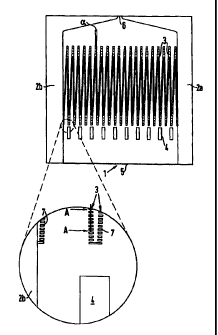
As mentioned above, Figure 1 shows an illustrative embodiment of a filter,
CA 02300908 2000-02-18
WO 99/16530 PCT/GB98/02604
9
viewed from the initially open side, which is then covered with the cover
plate (not
shown). A base plate I of the filter is microstructured between the edge
regions 2a
and 2b. The microstructuring provides, in this example. rows 3 of projections
which
are arranged in a zig-zag configuration. It may also be seen that the rows 3
are
inclined relative to each other through an angle alpha.
In this example, the base plate is provided, in addition to the filter and
upstream thereof, with a further row of projections 4 which form a very coarse
filter
and which serve to agitate the fluid flowing therethrough. Disposed upstream
of the
projections 4 is an inlet slot 5 through which the unfiltered fluid passes
into the filter.
In this embodiment, arranged adjoining the filter is a nozzle 6 out of which
the filtered
fluid can exit. The nozzle 6 has been formed, in this illustrative example, as
an
integral component of the base plate 1. It will be appreciated that the filter
can be
formed without the nozzle 6 and coarse filter 4.
Figure 2 is an enlarged view of a portion of Figure 1 showing an illustrative
arrangement of projections in the rows 3. In this case the projections 7 are
rectangular
webs or lands but, as will be described later, they may have an alternative
configuration. It can be seen that the rows 3 comprise a plurality of
projections 7
which upstand from the base plate 1 and which are spaced from one another to
provide a fine fluid filter.
Figure 3 is a cross-sectional view through a row of projections taken along
line
A-A in Figure 2. In this illustrative embodiment, the projections 7 have
concavely
curved longitudinal sides, between which there are passages 8 of barrel-shaped
cross-
section.
Figure 4 shows a plurality of embodiments of projections, each viewed from
the initially open side of the filter (i.e. from above). Any of, or any
combination of,
the illustrated projections (or any other projection) may be employed in the
filter
described herein. Figure 4 shows a rectangular land 11, an elongate land 12 of
constant width with rounded narrow sides, a wing-shaped land 13, a land 14 of
constant width and with an inclinedly extending narrow side, and a land 12
which is
curved in the shape of a segment of a circle. Also illustrated are a square
column 16,
a triangular column 17, a round column 18 and an octagonal column 19. As
mentioned above. any of or any combination of these lands are suitable for use
in the
CA 02300908 2000-02-18
WO 99/16530 PCT/GB98/02604
filter.
Figure 5 shows various cross-sectional views through a variety of different
projections, more specifically a projection of a rectangular cross-section 21,
a
projection of a cross-section 22 with concavely curved longitudinal sides, a
projection
5 of trapezoidal cross-section 23 in which the long side of the trapezium is
connected
to the base plate 1. a projection of trapezoidal cross-section 24 in which the
short side
of the trapezium is connected to the base plate 1, and a projection 25 with
two
rounded-off longitudinal edges.
Figure 6 shows various arrangements of projections wherein the projections -
10 irrespective of the form thereof - are indicated by dots of different
sizes. The
projections can be arranged in a matrix form 31 or linearly in a row 32 or in
a
meander configuration 33 or in a zig-zag configuration 34. A plurality of
projections
arranged in a row configuration 35 or in a meander or zig-zag configuration 36
can
be arranged in succession in cascade relationship.
Figure 7 shows an illustrative orientation of lands in relation to the intake
flow
direction 41 of the fluid. As shown, some of the lands (indicated with
reference
numeral 42) are arranged parallel to the intake flow direction, others of the
lands
(indicated with reference numeral 43) are arranged perpendicularly to the
intake flow
direction and the remainder of the lands (indicated with reference numeral 44)
are
arranged inclined at different angles to the intake flow direction. It should
be
understood from Figure 7 that the lands do not have to have the same
orientation with
respect to the intake flow direction. In fact, the provision of differently
orientated
lands is a distinct advantage as the differing orientation serves to improve
the degree
of fluid agitation as the fluid moves through the filter.
Figure 8 shows an image produced in a scanning electron microscope of a
microstructured filter such as that shown in Figure 1 at the end of its useful
service
life. The image was recorded through the cover plate (not visible) of glass.
The
image shown illustrates a filter having rows of projections arranged in a zig-
zag
configuration: however the projections themselves cannot be seen at the
selected
magnification.
Fluid has flowed through the filter in the direction of the arrows during use
of
the filter, and particles suspended in the fluid have become trapped by
adjacent
CA 02300908 2000-02-18
WO 99/16530 PCT/GB98/02604
11
projections. As shown. the rows of projections are covered with filtered-out
particles,
more specifically to a greater degree in the proximity of the edge regions 2a
and 2b
than in the central region of the filter. There are almost no particles in the
space
between the rows of projections, which is at the intake flow side of the
filter; and thus
the filter is fully operational in that region (i.e. fluid can still pass
therethrough). As
can be seen from Figure 8, the limit line between the free filter region and
the
obstructed filter region extends in an approximately parabolic shape. As seen
from
Figure 8, fluid can still pass through the filter even though a considerable
part of the
filter surface area has already been obstructed.
It can be seen therefore that the filter described herein is less prone to
blockage
than previously proposed filters, as it can still function adequately even
when a
relatively large proportion of the filter surface has been obstructed. As a
result of this
improvement, the useful life of the filter (and thus any devices including the
filter)
may be greatly increased. This is in direct contrast to previously proposed
arrangements where a relatively small amount of filter obstruction causes the
device
to cease functioning correctly.
Example: Microstructured filter for an atomiser
As mentioned above. the filter described herein finds great utility in
atomisers,
and in particular in atomisers for producing an aerosol of a medicament-
bearing fluid.
An illustrative example of one such atomiser will now be described. In this
illustrative example, the filter is formed on a base plate together with a
number of
other microstuctured components. The base plate is 2.6 mm wide and about 5 mm
long. On a width of about 2 mm it contains 40 rows of projections, with the
rows
arranged in a zig-zag configuration. Each row is 1.3 mm long. The projections
are
rectangular lands which are 10 m long and 2.5 m wide; and they project out
of the
base plate by 5 m. Provided between the lands are passages which are 5 Jim
high
and 3 m wide.
Disposed on the fluid entry side of the filter is a row of 10 rectangular
lands
which are 200 pm long and 50 gm wide; and they project out of the base plate
by
100 m. Provided between those lands are passages which are 100 m high and
150 m wide. The ten rectangular lands provide a course filter and a means for
CA 02300908 2000-02-18
WO 99/16530 PCT/GB98/02604
12
agitating the fluid flowing therethrough. At a spacing of about 300 p.m in
front of the
row of lands there is provided a fluid entry gap which is about 2 mm wide and
100
m high.
A filtrate collecting chamber is provided behind the rows of lands arranged in
a zig-zag configuration. The filtrate collecting chamber is 5 m high and
gradually
narrows from a 2 mm width and which communicates with a nozzle of rectangular
cross-section which is 5 m high and 8 m wide. In this example, the nozzle
opening
was produced at the same time as the microstructuring of the base plate.
The base plate which is 1.5 mm thick comprises nickel and is produced by
galvano-shaping of a plastic moulding insert which contains the complementary
structures for 1083 filters. It is covered with a 0.8 mm thick, flat nickel
plate which
is soldered to the base plate.