Note: Descriptions are shown in the official language in which they were submitted.
CA 02300963 2000-02-14
WO 99/66826 PCT/US98/19474
UNIVERSAL MODULAR LARYNGOSCOPE/GLOTTISCOPE SYSTEM
Technical Field
This invention relates to a universal glottiscope system which enables a
surgeon to perform laryngoscopic procedures on patients of differing anatomy.
More
particularly, it relates to a novel modular laryngoscope/glottiscope system in
which a
suspension handle may be selectively assembled and operatively attached to any
one of
a set of elongate tubular elements of different sizes.
Background Art
Instruments generally known as laryngoscopes are routinely used to
facilitate endotracheal intubation of patients, e.g., to provide a temporary
air passage for
administration of anesthetic substance or to overcome an obstruction of the
air passage
to a patient's lungs. Laryngoscopes, in various forms, are also commonly used
in
surgery to displace oral cavity and pharyngeal tissues to enable a surgeon to
perform
direct inspection and surgical manipulation of a patient's larynx, a procedure
known as
direct laryngoscopy. The typical laryngoscope has an elongate portion, which
may be
of adjustable geometry, that is introduced through the patient's mouth into
the larynx.
An attached handle enables the surgeon to manipulate not only the portion
introduced
into the patient's larynx but, as appropriate, to position the distal end of
the inserted
element to perform inspection and/or surgical operations. One or more surgical
tools
may be inserted simultaneously via the inserted element. Otolaryngologists
typically
use a laryngoscope having a tubular portion insertable into the patient's
larynx to the
glottis, i.e., the true vocal cords or folds, both for viewing and for
endoscopic surgical
operations thereon.
CA 02300963 2000-02-14
WO 99/66826 PCT/US98/19474
2
The surgeon must have a clear view of the affected tissue and must be able
to perform precise surgery, sometimes with more than one tool utilized
simultaneously.
Because of the limited dimensions of the human oral cavity, pharynx and
larynx, and
the inevitable discomfort suffered by the patient in such a procedure, it is
extremely
important to enable the surgeon to have the widest access and maximum freedom
for
manipulating necessary instrumentation, and to reduce the time during which
physical
invasion of the patient's larynx must occur.
Particularly for patients who need to improve or maintain their voices,
specialized surgery known as phonomicrosurgery is performed with the use of a
surgical
microscope. Such phonomicrosurgery is optimized by obtaining the widest
glottal
surgical field to expose vocal-fold anomalies such as polyps, nodules, cysts,
granulomas,
papilloma, epithelial dysplasia, and cancerous growths.
The human vocal folds (glottis) comprise an approximately isosceles-
triangle-shaped valve that is fixed anteriorly and opens and closes
posteriorly to allow
for respiration and phonation, respectively. Lesions of the vocal folds may
occur in
patients of all ages and of both genders. A clear human voice is predicated on
aerodynamically-driven, symmetrically-entrained oscillation of the vocal
folds. When
the vocal folds are closed during phonation, the expired air stream from the
trachea is
opposed by the closed glottal valve. Under sustained aerodynamic pressure, the
vocal
folds will vibrate to generate phonation. This vibration becomes disordered,
and
hoarseness develops, if there is a lesion on the vocal folds. Most benign
lesions of the
vocal folds, except lesions caused by viral infection, tend to develop in
vocal over-users.
Successful phonomicrosurgery depends on maximal preservation of the
layered microstructure of the healthy vocal fold tissue and is facilitated by
the largest
appropriately-shaped laryngoscope that can be placed between the patient's
lips and
glottis. Accordingly, the optimal laryngoscope will be one which facilitates
ideal
exposure of the pathology and, in turn, hand-instrument examination and
retraction of
the lesion for examination and resection.
In the known prior art, the problem of effectively angulating hand-held and
operated instruments within the lumen of the laryngoscope element inserted
into the
patient's mouth and larynx was solved in two ways: by forming the lumen
structure to
have a widened proximal aperture of a tubular laryngoscope or, in the
alternative, by
CA 02300963 2000-02-14
WO 99/66826 PCT/US98/19474
3
using a bivalved spatula laryngoscope comprised of two pivotably separable
distending
spatula blades. The latter tends to be unstable distally away from the
distending
mech-anism. A single slot was sometimes provided in the lumen to facilitate
manipulation of proximal end portions of surgical instruments therein, but
this provided
room for instrument manipulation on only one side of the laryngoscope. The
prior art
furthermore suffers from an inability to provide the dimensional versatility
required
when treating patients of differing anatomy.
A need exists for a modular glottiscope system which enables a surgeon
to treat patients of different sizes, permits access to specific portions of
the larynx with
greater precision and comfort for the patient, and permits flexibility in
manipulation of
one or more viewing and/or surgical tools and, because of its modular
variations, easily
adapts for intubation applications. The present invention is intended to meet
all of these
needs.
Disclosure of the Invention
Accordingly, in a first aspect of this invention, there is provided a novel
universal modular glottiscope system, which includes a plurality of elongate
tubular
elements of different counterpart dimensions, respectively, each element
having a distal
end to be inserted into a patient's larynx and a proximal end through which
one or more
surgical devices may be inserted operatively by the surgeon. An aperture is
defined
internally by the wall of the tubular element. The distal portion of each
tubular element
is of generally triangular cross-section, having a substantially planar base
that, in a
preferred embodiment, is detachable, and a pair of curved sides that intersect
above the
base. Preferably, the proximal portion is D-shaped in cross section with a top
that is
generally ovoid in configuration, and sides provided with respective slots of
predetermined width and length, located intermediate of the tubular element.
The
aperture of the tubular element at the proximal portion preferably is slightly
wider than
at the distal end, to accommodate to the optical requirements of a surgical
microscope.
The tubular elements are provided in a variety of sizes to facilitate choice
by the surgeon of the most appropriate one for a particular patient and a
particular
surgical operation. A standardized handle-attachment member is affixed to the
proximal
end of each of the tubular elements, and the system includes a handle manually
CA 02300963 2000-02-14
WO 99/66826 PCT/US98/19474
4
attachable to and detachable from the standardized handle-attachment member of
any
of the elongate tubular elements.
In another preferred embodiment of the apparatus, there is provided an
improved laryngoscope comprising an elongate tubular element having a distal
end to
be inserted into a patient's larynx and a proximal end through which one or
more
surgical devices may be inserted individually or simultaneously, the system
having a
handle attachable to a proximal end portion of the tubular element. The distal
portion
of the tubular element is configured with a generally triangular cross-section
defined by
a substantially planar base of a predetemiined length and a pair of curved
sides which
intersect at a predetermined first angle at an apex line located at a
predetermined height
relative to the base. The proximal portion of the tubular element is of a
configuration
defined by the substantially planar base and an upper part that is generally
ovoid. The
base of the tubular element at the proximal portion is wider than at the
distal end, to
accommodate entry of surgical devices.
Other aspects of the invention involve methodology for utilization of an
improved glottiscope system and apparatus of the type generally described.
These and other related objects, aspects and benefits of the invention
disclosed herein will be better understood by reference to the following
detailed
description and the attached drawing figures.
Brief Description of Drawings
Fig. I is a side perspective view of a set of three tubular elements, of
different dimensions but otherwise similar geometry, in accordance with the
invention.
Fig. 2 is a transverse cross-sectional view at the proximal portion of the
tubular element of Fig. 1.
Fig. 3 is a transverse cross-sectional view at the distal portion of a tubular
element of Fig. 1.
Fig. 4 is comparable to Fig. 3 for a smaller tubular element, with
detachable flat planar base-plate removed.
Fig. 5 is a bottom view of a tubular element, in accordance with one
embodiment of the invention, with detachable flat planar base-plate removed.
CA 02300963 2000-02-14
WO 99/66826 PCT/US98/19474
Fig. 6 is a bottom view of a larger tubular element with detachable flat
planar base-plate shown in position.
Fig. 7 is modified infra-lateral view of a tubular element.
Fig. 8 is an exploded side elevation view of a modular glottiscope system
5 with a simple handle and extension.
Fig. 9 is an exploded side elevation view of a variation of the glottiscope
system according to this invention, in a form more particularly suitable for
intubation
for the administration of anesthesia to a patient.
Best Mode for Carrying out the Invention
A modular glottiscope system according to an embodiment of the present
invention employs, with consideration given to the patient's physical size,
and with
reference to Figure 1, a set 100 of differently dimensioned elongate hollow
tubular
elements l 00A- l 00C, at the distal end of each of which is an opening 102
defined by
intersection of the tubular form shown with an imaginary plane. A routine
longitudinal
clamp-on light carrier (not shown) generally is used to provide illumination
through the
lumen of the glottiscope while it is being positioned with respect to the
patient. It
should be understood that other tubular elements intended to be part of the
modular set
will have the same geometry but be of different dimensions. What is the same
for all
the elongate tubular elements 100 of a given set 100 of such elements is that
each is
provided with a handle-attachment member 104 (not shown in Fig. 1; see Figs. 8
and
9) of a standard shape and size to permit easily detachable attachment to a
suitable
handle (to be described later).
Each tubular element has a flat planar base 106, which can be detachable,
of length a proximal width "Pw,a" (Fig. 2) and a distal width "DWa" (Fig. 3).
Base
106 is smoothly contiguous with a pair of curved sides 108, 110 which
intersect above
at an apex line 112. The base 106 has opposite recessed sides that receive and
mate
with the corresponding inwardly extending ends of sides 108, 110, as best
shown in Fig.
3, such that the base can be separated from element 100 by sliding the base
rearward
from the proximal end of the element. The base 106 is aligned longitudinally
in the
tubular element by internal extensions 111 that seat within corresponding
recesses of
sides 108, 110.
CA 02300963 2000-02-14
WO 99/66826 PCT/US98/19474
6
The respective intersections between curved sides 108 and 110 at apex line
112, of curved side 108 with planar base 106 at 114, and of curved side 110
with planar
base 106 at 116, are all formed to have smoothly rounded outside surfaces to
avoid
inflicting unnecessary trauma to the patient's tissues. Similarly, where
distal end
opening 102 is defined by intersection of this complex triangular cross-
section with an
imaginary plane inclined at an angle "a" to rounded apex 112, the opening edge
is also
smoothly rounded. A preferred range of a is 35 - 70 . The goal is to avoid
inflicting
unnecessary trauma on the patient's tissue as the distal end, with opening 102
therein,
is inserted into the patient's mouth and larynx.
At the proximal end of each tubular element 100, beneath handle
attachment member 104 (Figs. 8 and 9) and adjacent the base is provided a pair
of
laterally opposed slots 118 and 120, respectively formed in curved sides 108
and 110.
The upper edges of slots 118 and 120 are preferably, but not necessarily,
parallel to the
planar base. The height of each of these slots, namely "Sq,a", is selected to
permit
movement therein of the viewing and surgical operation tools which the surgeon
expects
to use. The length of slots 118 and 120, namely "S,a", likewise is chosen to
suit the
surgeon's needs. The width PWa of the proximal portion of the base 106 is
greater than
that (D,õa) at the distal end, to accommodate the surgeon's instruments. The
width of
base 106 may decrease gradually from the proximal to distal ends (Fig. 6).
An important advantage of the invented system is that it permits modularity
and, based on actual measurements and/or the surgeon's experience, allows the
surgeon
to select the particular elongate tubular element 100A-C which will most
effectively
permit inspection and/or surgical treatment of that patient's glottal tissue.
The surgeon
has the freedom to select the most suitably sized and shaped tubular element
and to
readily and securely attach it, via its standardized handle-attachment member
104, to a
standardized handle structure (to be described later). The surgeon thus can
easily adjust
to the needs of patients of differing anatomy, since it is intended that the
set of elongate
tubular elements 100 should include elements of all the necessary lengths and
diameters,
etc.
However, many surgical tools probably carmot be reduced in size
indefinitely without adversely affecting their effectiveness. There may be a
minimum
size for the width and length of the parallel slots below which one may not go
without
CA 02300963 2000-02-14
WO 99/66826 PCT/US98/19474
7
adversely affecting the surgeon's ability to manipulate tools inserted
longitudinally
through that elongate tubular element by sideways lateral movement of parts of
the tools
in and out of the respective slots 118 and 120. The key is that the present
system
permits a considerable degree of flexibility to suit the instrumentation to
the
particularized needs of individual patients. If certain minor compromises have
to be
made, as just discussed, these still should not detract from the overall
flexibility of the
system in a laryngoscopic surgical practice.
As is also readily seen from Fig. 2, the proximal end portion of each
elongate tubular element 100, immediately above the laterally opposed slots
118 and
120, is generally D-shaped in configuration with the form of a gently curved
"inverted-
U". Such a structure inherently possesses a degree of stiffness which,
together with
affixation to the preferably cylindrical handle-attachment member 104,
provides
sufficient rigidity and strength at the proximal end to permit the transfer of
significant
forces which must be applied in the course of surgery and treatment. In other
words,
the sizing and disposition of the slots to allow the residual portion of the
tubular
structure to have an inverted "U" form above for structural rigidity is
deliberate and
intended to ensure that the tubular element has sufficient inherent strength
to perform
all of its intended functions. Obviously, the thickness of the tubular element
100 and
the choice of material from which it is made must also be taken into
consideration in
normal manner.
It is expected that after a particular surgical use the elongate tubular
element 100 will be cleaned and sterilized, for subsequent reuse, which will
be
facilitated by the fact that the planar base separates from the upper arched
segment of
the tubular element. This requires that the materials employed must be both
tissue-
compatible, i.e., capable of resisting any acidic substances (natural or
medically
applied), and capable of tolerating sterilization without adverse effect.
There are
numerous alloys and plastics available for such instruments, and stainless
steel is a
commonly preferred material. Any such known material, capable of providing,
the
required strength, tissue compatibility and sterilization-tolerance, may be
considered by
persons of ordinary skill in the art to meet specific needs.
As mentioned earlier, a key feature of the present system is that it has a
high degree of modularity. This comprises not only selection of dimensions for
tubular
CA 02300963 2000-02-14
WO 99/66826 PCT/US98/19474
8
elements 100 -but also in the curvatures and, therefore, the angle of
intersection 13,"
between the curved sides 108 and I10, as seen in Fig. 4. This angle is
determined
between the two planes respectively tangent to the curved sides 108 and 110 at
the apex
line 112. Varying the height "h" for a given distal base width "DW" and/or
varying the
curvature of each of the sides 108, 110, may result in a different angle,
i.e., "B2" at the
intersection of the curved sides at apex line 112 at the distal end of the
tubular element.
A preferred range of B is 45 - 120 . It may also permit variation in the width
of the
opposed slots, and thus the geometry of the space available to the surgeon to
manipulate
portions of surgical tools within the slots. Likewise, different sizing may be
accomplished at the proximal end. In general, the base width at the proximal
end, PW,
will be greater than that at the distal end (DW).
As persons skilled in the art of mechanical design will readily appreciate,
the curvature of each of the sides 108 and 110 need not be truly arcuate,
namely sectors
of a perfect circle. In fact, because the normal human glottis has a
particular shape, it
may be desirable to form the sides 108 and 110 so that there is a different
local radius
of curvature at different points between the base and the apex line. The sides
of
varying curvature with the portions close to apex line 112 at the distal end
may be of
a smaller radius of curvature than portions closer to base 106. This can be
reversed,
i.e., the sides 108 and 110 may be curved so that they have a smaller local
radius of
curvature closer to base 106 than they do close to apex line 112. The
curvature of the
upper part of the proximal end may be similarly varied. These are mere matters
of
choice and the modularity of the present system readily accommodates such
variations
so that the surgeon may have the greatest flexibility to meet the needs of
individual
patients and surgical operations.
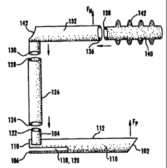
Fig. 8 is an exploded side view of certain basic components of a
glottiscope according to a preferred embodiment of this invention. In this
structure,
which can be readily assembled, there is included a selected one of the
elongate tubular
elements 100 as described above. Handle-attachment member 104 may be readily
made
of the same material as tubular element I10 and may be welded, brazed, or
otherwise
affixed thereto. Over the distal end 122 of handle-attachment member 104 may
be
fitted a lower end 124 of an elongate tubular extension element 126. One of
the
modular aspects of the present invention is that such extension elements 126
may be
CA 02300963 2000-02-14
WO 99/66826 PCT/US98/19474
9
provided in a variety of lengths, although each should preferably have a
standardized
inside diameter selected to closely fit to the standardized handle-attachment
member
104. Into the opposite end 128 of extension element 126 may be inserted a
short lateral
connector part 130 of a generally "L" shaped handle 132. In the embodiment
shown
in Fig. 8, handle 132 has a first end 134 which may be closed off and be
perpendicular
to the longitudinal direction. Into a distal end opening 136 of handle 132 may
be
inserted a first end 138 of a handle extender element 140 which may be
provided with
an outer flexible cover having easy-to-grip ridges 142. In such a structure,
what has
hitherto been referred to as handle 132 may be considered an intermediate
element
between handle extender 140 and extension element 126 of the structure thus
described.
Some surgeons may prefer to have extension element(s) 126 of other than
a right cylindrical shape. Ergonomically suitable shapes for extension element
126 may
be considered within the scope of this invention, e.g., having a central
portion is made
of irregular and/or larger cross-sectional size while both end portions are in
the form
of circular right cylinders made smoothly contiguous with the central portion.
It is intended that extension element 126 be securely fittable to handle-
attachment member 104, that lateral portion 130 of handle 132 be securely
fittable to
the opposite end 128 of extension element 126, and that end 138 of handle
extender 140
be securely fittable to end 136 of handle portion 132 easily. For reasons of
scale, Fig.
8 does not show minor details of how the actual details of such a mechanism
would
appear. It is considered that persons of ordinary skill in the art will be
aware of and be
able to adapt any of numerous known structures and techniques for providing
such
secure but readily detachable attachments. Examples of such detachably
attachable
mechanisms include bayonet fittings, and as generally available in known
systems for
the same general purpose. The exact nature and form of such mechanisms is not
critical
to the present invention. All that is required is that various attachments be
capable of
easy and secure attachment and ready detachment as necessary for separate and
effective
sterilization of the various parts.
To facilitate the surgeon's activity, it is highly preferable to make
extension
element 126, handle portions 132 and 130, as well as handle extender 140 (if
used), all
of strong but relatively lightweight materials. Numerous alloys, composites,
and other
materials for such purposes are well-known to persons of ordinary skill in the
art, and
CA 02300963 2000-02-14
WO 99/66826 PCT/US98/19474
any of these may be selected as desired. The exact choice of materials is not
considered
critical for this invention, although it is preferred that the entire
structure be relatively
light. The key is that during use the surgeon may be expected to attach either
handle
portion 132 or handle extender 140, in any known manner, to an external
suspension
5 system and to manipulate the same to apply significant forces to the patient
against the
pull of gravity.
A smoothly curved corner surface is provided to handle 132 to provide
ergonomic rest for the surgeon's thumb of the hand holding extension element
126
during manipulation of the glottiscope. In other words, a surgeon grasping
handle
10 portion 132 or handle extender 140 (if one is used) with one hand may grasp
extension
element 126 with his or her other hand while resting the thumb of that
particular hand
on the curved recess surface 142 for comfort and convenience.
Known suspension and fulcrum-holder systems for such equipment include,
but are not necessarily limited to, the well-known Boston University
Suspension System,
the Loeb Laryngoscope Holder Support, and other "gallows"-type systems known
in this
art. This may require the addition of appropriately formed known elements to
the
components described hitherto. Such obvious modifications are considered well
within
the knowledge of persons of ordinary skill in the art, various elements of
such systems
are well-known and commercially available, and a detailed description thereof
is
therefore believed to be unnecessary and is omitted for conciseness.
As indicated in Figs. 8 and 9 by bold arrows identified as "F,j" and "FP",
where a force "FH" is applied by the surgeon via the handle structure, with
tubular
element 110 inserted into a patient's larynx, a consequential force "Fp" will
be exerted
on the patient. These forces can be significant, and a principal reason for
choosing the
depicted cross-section for tubular element 110, with curved sides coming
together at a
smoothly curved apex line, is to facilitate the application of such a force in
a manner
most advantageous for the surgeon without inflicting unnecessary trauma on the
patient's tissues. Persons of ordinary skill in the art of performing
laryngoscopic
procedures will understand exactly how such forces are applied and why they
are
necessary to provide appropriate access to tissue to be treated.
The embodiment of Fig. 9 is particularly suitable for anesthesia applications
in which a patient is intubated for the controlled provision of an anesthetic
substance.
CA 02300963 2000-02-14
WO 99/66826 PCT/US98/19474
11
In this modified structure, tubular element 100 may be exactly the same as
described
above, as is extension element 126 detachably attachable thereto at handle-
attachment
104. The handle extender 140, described above with relation to Fig. 8, is
omitted, and
the extension element 126 may be used alone with the tubular element 110
(giving the
assembled instrument a generally L-shape) or with the handle 132, extension
element
126, and the tubular element 110 (giving the instrument a generally C-shape).
For
intubation purposes the surgeon will introduce an anesthetic-delivery
endotracheal tube
longitudinally through the tubular laryngoscope element 100 and out of end
opening
102, through the vocal fold aperture and into the patient's trachea. Once this
is
satisfactorily done, the detachable planar base can be detached so that the
upper portion
of the glottiscope can be removed from the patient's throat without disturbing
the
endotracheal tube. This approach is invaluable in the difficult intubation
such as is
encountered with tumors that are obstructing the pharynx and/or larynx.
Subsequently,
an anesthetic substance, by itself or mixed with other substances, can be
administered
at a controlled rate for as long as needed. Similar intubation may be employed
to suck
out liquids from a patient's lungs through the trachea. Such obvious
procedural
modifications in the use of the hitherto described elements is expected to be
well within
the reach of persons of ordinary skill in the art.
When the system is to be employed for laryngoscopic/glottiscopic
procedures, the elongate tubular element 100 will be positioned in the larynx
of a
conveniently disposed patient with the outer surface of the base part of the
element
cross-section immediately adjacent the patient's upper mandible. This will
ensure that
the apex line is immediately adjacent the lower mandible of the patient, and
this is
particularly suitable, with appropriate choice of dimensions of the tubular
element 100,
for applying the distal end to the laryngeal tissue in the most advantageous
manner.
Descriptions will now be provided of methods of using the above-disclosed
universal glottiscope system for applications such as phonomicrosurgery and
intubation
for administration of anesthetic gases.
The performance of phonomicrosurgery on a particular patient will require
an initial gross examination of the patient's oral cavity, larynx and pharynx,
possibly
with preliminary measurements, to determine the optimum dimensions and shape
(determined by the apex angle and curvature distributions of the curved sides
of the
CA 02300963 2006-09-11
12
substantially triangular cross-section) for the patient. If the patient is a
relatively small child,
the surgeon may wish to select a tubular element 100 which has a slightly
flared proximal end,
e. g., to permit the use of a conventional microscope for viewing thereat. If
the tubular
element has been selected from a particular subset of a larger set of such
elements, the surgeon
may then select the appropriate universal handle system.
The patient will then be put in the most appropriate position for his or her
needs, size, and comfort. U. S. Patent No. 5,092,314, to Zeitels, in Fig. 4
and in its
specification provides an explanation of how the well-known Boston University
Suspension
System may be utilized and the patient positioned in an exemplary application.
These and
other related portions of Zeitels are exemplars of what is known in this art.
Once the patient
is appropriately positioned, the surgeon will insert the distal end of the
tubular element 100
into the patient's mouth and larynx, with the curved sides initially
operatively disposed
adjacent the patient's upper and lower teeth and with the apex line
operatively disposed
adjacent the patient's buccal mucosa. Afterthe distal end of the tubular
element 100 has passed
the patient's circumvallate papilla at the origin of the tongue base, the
tubular element must
be rotated, e. g., counterclockwise, about 90 . The apex at the distal tip,
where the apex line
112 ends at the top of opening 102, is then placed under the laryngeal surface
of the epiglottis.
At this time, the planar base of the tubular element 100 distracts the
endotracheal tube
posteriorly, between the arytenoids out of the surgical field, exposing the
musculo-
membranous vocal folds. The distal end is then advanced further to distract
the false vocal
folds laterally and to establish maximum exposure of the patient's true vocal
folds.
It should be appreciated that the selected angle at the apex of the tubular
element 100 most have been chosen to enable optimal lateral distraction of
that particular
patient's false vocal folds for exposure of a superior surface of the true
vocal folds. When this
is done appropriately, there will be available a very clear visualization of
the patient's true
vocal fold pathology. The surgeon can thereafter dispose suitable instruments,
individually or
simultaneously, longitudinally of the tubular element 100 to perform surgery
on the musculo-
membranous tissue of the patient's true vocal folds. In doing so, the surgeon
will have the
benefit of the pair of bilaterally opposed end slots 118 and 120 through which
to manipulate
proximal end portions of the viewing and/or
CA 02300963 2000-02-14
WO 99/66826 PCT/US98/19474
13
surgical instruments more comfortably than was possible with the known
structures of
the kind which included only a single slot on one side.
Certain individuals may have anatomical characteristics which may create
difficulties in the practice of conventional techniques for direct intubation,
for example,
for administration of anesthetic gases. It is also possible that even average
individuals
may have unique personal pathologies which might be unacceptably disturbed or
traumatized during conventional intubation. This could complicate and perhaps
even
compromise subsequent endoscopic laryngeal procedures. The present invention
provides a solution for such needs.
As described earlier with reference to the phonomicrosurgery procedure,
the surgeon must initially decide on a suitable dimension and shape of an
elongate
tubular element 100 selected from a set thereof. One of the factors to be
considered is
the known and/or anticipated form of the patient's pathology. The patient is
positioned
so that either the cervical spine is in flexion with regard to the thoracic
spine with the
cranium in extension with regard to the cervical spine, or with the cranium in
flexion
with regard to the cervical spine. External counter-pressure may be applied
manually
to the patient's lower laryngeal cartilage framework. When the patient's
glottal aperture
and vocal fold pathology are adequately visualized with the glottiscope and
its
conventional lighting/optical devices attached longitudinally along the
tubular element
100, the distal end of an endotracheal tube is gently passed through the
glottal aperture
and away from the vocal fold pathology. A conventional cuff provided at the
end of
the endotracheal tube is then inflated so that controlled flow of anesthetic
gases can be
administered to the patient. Since the connector at the proximal end of the
endotracheal
tube will not fit through the lumen of the glottiscope, the planar base plate
106 of the
glottiscope is removed so that the glottiscope separates into two segments,
thus allowing
for the upper portion of the tubular element to be removed from the throat
without
disturbing the endotracheal tube. This approach facilitates safely placing an
orotracheal
tube in a patient with obstructing throat pathology, however it may facilitate
many other
types of difficult intubations.
Obvious variations of these methods will no doubt occur to persons of
ordinary skill in the art, e.g., surgeons and operating room staff, as the
advantages of
CA 02300963 2000-02-14
WO 99/66826 PCTIUS98/19474
14
the structure -disclosed herein become apparent through use, practice and
shared
experience.
As will be clear to persons of ordinary skill in the art, various types of
known tools, devices and mechanisms can thus be readily used with the present
invention for lighting, surgery, photography, suction, etc. as best suits the
surgeon's or
anesthesiologist's needs.
The fact that the surgeon or anesthesiologist has a variety of tubular
elongate elements as taught in this invention facilitates precise
accommodation of the
laryngoscope to individual patient anatomy and lesion characteristics. The
substantially
triangular cross-section distally with the smooth apex line at a suitable
angle between
curved sides, facilitates a comfortable and effective fit of the distal end to
the human
glottis. The provision of two opposed slots at the proximal portion of the
tubular
element provides exceptional freedom for the surgeon to manipulate the
proximal ends
of elongate instruments, one or more at the same time, selectively introduce
longitudinally of tubular element 100. For the smallest tubular elements,
i.e., pediatric
sizes, greater proximal widening of elongate tubular elements 100 may be
necessary so
that illumination from the surgical microscope (if one is used) does not
reflect and cause
glare off the edge of the proximal inner surface portion of the tube.
Although tubular elongate element 100 is shown in the drawing figures and
is generally discussed above as being straight, there is no reason why it may
not be
made curved, the maximum benefits being realized by providing the above-
described
substantially triangular uniform cross-section with curved sides, the
bilaterally opposed
proximal slots, and the standardized handle-attachment at the proximal end.
Although the present invention has been described and illustrated in detail,
it should be clearly understood that the same is by way of illustration and
example only
and is not to be taken by way of limitation, the spirit and scope of the
present invention
being limited only by the terms of the appended claims.