Note: Descriptions are shown in the official language in which they were submitted.
CA 02301058 2000-02-15
Pruftechnik Dieter Busch AG PCT/DE 99/01786 P 359 - PCT
D 85737 Ismaning
Title of the Invention:
Shock protection for position measuring probes
Description
The present invention relates to a shock
protection device for position measuring probes or
gyroscopes, in particular those which are equipped with
an optical gyroscopic system or with a mechanical
oscillator. Moreover, the invention can be used with an
advantage as shock protection for precision instruments
which have a certain shock susceptibility.
Prior art
A shock protection system for position
measuring probes of the said type, in particular as
described in DE 19800534.2 or DE 19546405.2, is not
known. The devices used by the person skilled in the
art in order to protect chronometers or electric
precision instruments such as, for example,
galvanometers against shock cannot be used in this
regard.
Object of the invention
The problem on which the invention is based
consists in the following: when use is made of position
measuring probes of the said type they have to be
protected against excessive shocks or accelerations.
This is based, in particular, on the sensitivity of the
components used to such shocks. Substantial repair
costs can therefore arise through inadvertently
dropping such instruments. On the other hand, the said
position measuring probes must be applied to a surface
to be measured in a defined fashion, that is to say
with mechanical precision without backlash or damaging
flexibility. These aspects oppose one another to a
certain extent, since it is not possible to fit
conventional cushioning to the probes discussed here
without adversely affecting their measuring accuracy.
CA 02301058 2008-03-12
la
Certain exemplary embodiments can provide shock
protection for a position measuring probe, which is
provided for checking an absolute or relative position of
an object with respect to a fixed coordinate system,
defined by the following features:
the position measuring probe can be brought into a
first operating state by means of a device which can be
actuated manually or by motor, in which the probe is
protected against shocks acting from outside, but in
which the probe is disabled from position measurement
capabilities, and
the position measuring probe can be brought into a
second operating state by means of the device which can
be actuated manually or by motor, in which the probe can
carry out position measurements, but is only partially
protected against shocks acting from outside.
Certain exemplary embodiments can provide shock
protection for position measuring probes which serve for
checking the alignment of objects, the position measuring
probes having one or more gyroscopic systems, defined by
the following features:
the gyroscopic systems are located inside a
protective housing with permanently or temporarily
provided openings,
the gyroscopic systems can be moved relative to the
protective housing,
the gyroscopic systems, the enclosing housing or an
instrument panel have a plurality of bearing surfaces or
bearing points for making contact with the objects to be
aligned,
CA 02301058 2008-03-12
lb
the gyroscopic systems can be brought into a rest
position protected against shock, in which it is only
possible to carry out a crude check of the alignment of
objects or a comparable measurement,
the gyroscopic systems can be brought into a working
position unprotected against shock in which the
gyroscopic systems, the bearing surfaces or the bearing
points make direct contact with an object to be measured,
with the result that it is possible to carry out an exact
check of the alignment of the said object to be measured,
and
in the rest position protected against shock, the
gyroscopic systems are protected relative to the
protective housing against shocks, which act on the
latter, by means of one or more anti-shock devices or
buffers.
Certain exemplary embodiments can provide shock
protection for position measuring probes, defined by the
following features:
an outer shell is present which can be applied to a
surface to be measured,
at least one inner shell is present which encloses
one or more position sensors, in particular angular
position sensors,
the inner shell is spaced apart by one or more
cushioning or shock-absorbing elements with reference to
an outer enclosing shell or a bearing surface during a
time phase in which anti-shock functions are prioritized,
the inner shell is brought into self-closed
mechanical contact with reference to an enclosing outer
CA 02301058 2008-03-12
1c
shell or a bearing surface during a phase for
detecting measured values, and
the inner shell can be brought into defined
mechanical contact with the outer shell or a bearing
surface manually or by means of an electromechanical
device.
Certain exemplary embodiments can provide a shock
protection device for protecting a position measuring
probe comprising:
an outer shell;
an inner shell for supporting said position
measuring probe, said inner shell being movably disposed
within said outer shell to allow relative displacement of
said inner shell relative to said outer shell when said
shock protection device is in an operating state;
at least one shock-absorbing means disposed between
said outer shell and said inner shell for absorbing shock
exerted on said outer shell thereby protecting said
position measuring probe supported on said inner shell
against shock exerted on said outer shell when said shock
protection device is in an operative state; and
at least one engagement means for engaging said
inner shell to said outer shell to thereby establish
precise positioning of said inner shell relative to said
outer shell when said shock protection device is in an
inoperative state,
wherein said position measuring probe measures at
least one of an absolute position and a relative position
of an object with respect to a fixed coordinate system.
CA 02301058 2008-03-12
1d
Certain exemplary embodiments can provide a shock
protection device for protecting a gyroscope of a
position measuring probe adapted to measure at least one
of an absolute position and a relative position of a
cylindrical object with respect to a fixed coordinate
system comprising:
an outer shell adapted to engage said cylindrical
object;
an inner shell adapted to support said gyroscope,
said inner shell being movably disposed within said outer
shell to allow relative displacement of said inner shell
relative to said outer shell in at least two degrees of
movement when said shock protection device is in an
operating state;
at least one elastic cushioning element disposed
between said outer shell and said inner shell for
absorbing shock exerted on said outer shell thereby
protecting said gyroscope against shock exerted on said
outer shell when said shock protection device is in an
operative state; and
at least one engagement device adapted to engage
said inner shell to said outer shell along a bearing
surface provided on at least one of said outer shell and
said inner shell to thereby establish precise positioning
of said inner shell relative to said outer shell when
said shock protection device is in an inoperative state.
CA 02301058 2000-02-15
Pruftechnik Dieter Busch AG P 359 - PCT
D 85737 Ismaning - 2 -
In accordance with the invention, the present
problem is solved by providing for position measuring
probes a shock protection which is temporarily
deactivated on the occasion of a measuring operation to
be carried out, or is made available only
proportionally. For this purpose, in a first basic
embodiment the shock protection has the following
features:
- an outer housing shell is present which can be
applied to a surface to be measured in a defined
fashion,
- at least one inner housing shell is present which
encloses one or more sensors or instruments, in
particular angular position sensors,
- the inner housing shell is spaced apart by one or
more cushioning or shock-absorbing elements with
reference to an outer enclosing housing shell or a
bearing surface during a time phase in which
anti-shock functions are prioritized,
- the inner housing shell is brought into
self-closed mechanical contact with reference to
an enclosing outer housing shell or a bearing
surface during a phase for detecting measured
values, and
- the inner housing shell can be brought into
self-closed mechanical contact with the outer
shell or a bearing surface by means of an
electromechanical device or manually.
In a second basic embodiment, the shock
protection according to the invention for a position
measuring probe has the following features:
- the position measuring probe can be brought into a
first operating state by means of a device which
can be actuated manually or by motor, in which it
is protected completely against shocks acting from
outside, but in which it cannot be used for the
purposes of position measurement, and
CA 02301058 2000-02-15
Pr{iftechnik Dieter Busch AG P 359 - PCT
D 85737 Ismaning - 3 -
- the position measuring probe can be brought into a
second operating state by means of the device
which can be actuated manually or by motor, in
which it can carry out position measurements, but
during the period of which it is not completely
protected against shocks acting from outside.
It is now possible in accordance with the
invention to protect position measuring probes and
gyroscopes based on optical gyroscopes, specifically
fiber-optic gyroscopes, and those having one or more
mechanical vibrators (oscillators) against shocks
during transportation, during operation and also when
being applied to a surface to be measured. Such
surfaces can specifically be the cylindrical surfaces
of rollers such as are used to produce films, foils,
sheets and paper materials, and which must have a
highly accurate parallelism. The invention is therefore
particularly suitable for carrying out a very accurate
measurement of the parallelism of such rollers without
there being a large risk of inadvertently damaging the
relatively cost intensive measuring apparatus used by
incorrect deposition, mounting or by dropping.
In accordance with the first basic embodiment,
the invention is based on the fact that instead of a
single housing for appropriate devices, provision is
now made of a housing which has an inner and an outer
shell. The two shells are spaced apart from one another
in the inactive state of the probe by a special
cushion. A measuring system located inside the inner
housing shell is thereby protected elastically against
shocks. Not until shortly before the determination of a
measured value and after the measuring probe has been
brought into a measuring position of interest is an
electrically operated device used to ensure that the
inner and outer shells are brought into mechanical
contact with one another which is defined with high
accuracy. Immediately after the measured value is
taken, it is ensured that the mechanical contact
CA 02301058 2000-02-15
Priiftechnik Dieter Busch AG P 359 - PCT
D 85737 Ismaning - 4 -
between the two shells is released again. Instead of
the electrically operated device which makes the
mechanical contact, it is also possible to provide a
device which operates similarly and is to be actuated
manually and which can be configured more simply in
structural terms. A device operated by compressed air
can also be provided for comparable problems requiring
a relatively large housing. A typical cycle of a
measuring operation thus consists in that the measuring
probe is applied to a surface to be measured, a trip
element or switch is then actuated by means of the
electrically operated device to produce precise
mechanical contact between the two shells, and an
electronic system (preferably located in the interior
of the two shells) then senses and electronically
evaluates the positional and/or angular values of
interest, and thereafter the mechanical contact between
the two shells is released again by the electrically
operated device. The measured values obtained are
further used and evaluated after these steps.
In accordance with the invention, mechanical contact is
made between the inner and outer shells preferably by
means of a contact-making movement in the direction of
one of the spaced diagonals of these shells, with the
result that the periphery of the inner shell can make
contact with at least three bearing points on the
inside of the outer shell. The outer shell acts in this
way to a certain extent as a mechanical guide prism for
the inner shell. It is possible in accordance with the
invention to provide any desired elastic materials as
cushioning for the purpose of absorbing shocks on the
said inner shell with respect to the outer shell.
However, it is advantageous to provide expanded
silicone materials as cushioning, since not only can
these be used over a large temperature range and are
virtually nonflammable, but their elastic properties
also show no particularly pronounced temperature
response.
CA 02301058 2000-02-15
Pruftechnik Dieter Busch AG P 359 - PCT
D 85737 Ismaning - 5 -
I:xdlClp l. e s
The invention is explained below with the aid
of the preferred exemplary embodiments in accordance
with Figs 1 and 2, in which:
Fig. 1 shows the fundamental principle of a
first basic embodiment for a device acting in two
dimensions, and
Fig. 2 shows the fundamental principle of a
second basic embodiment.
Although the arrangement shown in Fig. 1
displays shock protection in two directions, it can be
used directly to produce a device working
correspondingly in three dimensions. Fig. 1 shows, as a
representation of a section, the interspace between the
said shells which is fitted with an electromechanical
device. A representation of those corners or edges of
the position measuring probe which are not used to make
mechanical contact between the said shells is dispensed
with. In detail, reference numeral 1 denotes an outer
shell of the housing according to the invention for a
position measuring probe or for a precision instrument,
while an associated inner shell is identified by
reference numeral 3. If they are not in direct
mechanical contact with one another, the two shells 1
and 3 are spaced apart mutually from one another by
one, preferably a plurality of elastic cushioning
elements 10, and with a prescribed elasticity. They
thereby protect an arrangement situated in the inner
shell 3, specifically a gyroscope, against mechanical
shock. A cushioning element 10 preferably consists of
an expanded elastic material or an elastomeric
material. It preferably has an approximately
semicircular cross section and is fixed on the inner
shell 3 by means of a heat-resistant adhesive layer 11.
In order to achieve a sufficient spring excursion for
the cushioning element 10, the latter is preferably
inserted into depressions 12 which are recessed into
CA 02301058 2000-02-15
Pruftechnik Dieter Busch AG P 359 - PCT
D 85737 Ismaning - 6 -
the inner shell 3 and thereby define local projections
9 which serve as bearing surfaces for making mechanical
contact. A relative movement of the inner shell 3 in
the direction of the outer shell 1 can thus take place
only against a spring force. The damping properties of
the cushioning element 10 can be varied depending on
whether the elastic material which is used in said
element is specified rather as being open-cell or as
being solid.
The elastic connection between the inner shell 3 and
outer shell 1 can be undone temporarily by activating
the electromechanical device 4 (with terminal contacts
5 and 6) located in a corner of the outer housing 1.
The electromechanical device 4 is fixed on the outer
shell, for example by means of a fixing bracket 2, and
is preferably constructed as a low-volume DC linear
motor. The push rod 7 thereof can either draw or push
the inner housing 3 in the direction of the arrowheads
A or B by means of a spring element 8, depending on the
type of its power supply. Thus, if the inner housing 3
is drawn in the direction of the arrowhead A the result
of this is that the projections 9 are applied
sequentially (possibly simultaneously) to the inner
surfaces of the outer shell 1. As a result, the shells
1 and 3 are in an exactly defined position relative to
one another, and the spatial position and orientation
of the outer shell 1 is transmitted to those of the
inner shell 3. In this phase, which usually corresponds
to a measuring phase, the shock-reducing effect of the
cushioning elements 10 is eliminated, as is that of the
elastic element 8. After termination of a measuring
operation, the inner shell 3 is pushed back again by
the electromechanical device 4. The cushioning elements
10 thereby once again take over the function of
providing spacing and reducing shocks between the outer
and inner shells.
If it is to be possible to bring the outer and inner
shells into contact with one another in all three
CA 02301058 2000-02-15
Priiftechnik Dieter Busch AG P 359 - PCT
D 85737 Ismaning - 7 -
coordinates of space, it is advantageous to provide the
drawing/pushing direction of the electromechanical
device 4 approximately in the direction of the
corresponding space diagonals of a shell. Success is
achieved in this way in creating an exactly defined
relative position between the inner shell 3 and outer
shell 9.
A second solution of the above-named problem is
provided in accordance with Fig. 2, which shows another
device according to the invention in a cross-sectional
view:
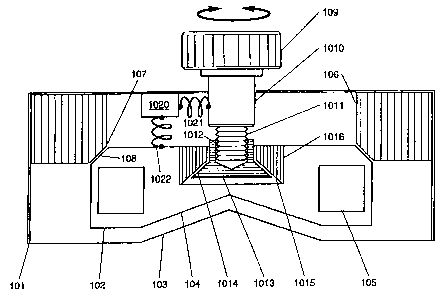
Located inside an outer shell 101 serving as protection
against mechanical effects, is an instrument panel 102
which holds or supports a measuring instrument
susceptible to shock, for example a gyroscopic system
105 (drawn schematically). The gyroscopic system can
also comprise a plurality of gyroscopes aligned
orthogonally relative to one another. The outer shell
101 is closed almost on all sides, but has an opening
in the form of a cutout 103 on the bottom surface and
the lateral surfaces (opening in the bottom surface not
identified in more detail). Owing to the cutout 103,
the instrument panel provided with a prismatic bearing
surface 104 can, if required, be brought into direct
and highly accurate mechanical contact with a
cylindrical roller situated below the cutout 103, or
with another object to be measured. However, the
position of the instrument panel 102 shown in the
figure represents a first operating state of the device
according to the invention, in which protection is
provided against shocks acting from outside by
shock-absorbing elements such as, for example, an
expanded plastic cushion 106. In order to be brought
from this position into mechanical contact with a
cylindrical roller located therebelow, it is necessary
for the instrument panel 102 to be lowered. Provided
for this purpose is a device which is operated manually
or by motor and comprises, as shown, for example a
CA 02301058 2000-02-15
Priiftechnik Dieter Busch AG P 359 - PCT
D 85737 Ismaning - 8 -
screw 1011 and a coupling plate 1013 provided with a
threaded bore 1012. Screw 1011 can be turned in a
right-handed or left-handed fashion by the rotary
button 109 and/or an electric motor drive (by motor
1010) , with the result that it is possible to effect a
variable spacing of the coupling plate 1013 relative to
the underside and topside of the outer shell 101.
Coupling plate 1013 preferably has a conical surface
1014, so that the instrument panel 102 can be raised or
lowered by means of a shock-absorbing element,
essentially permanently connected to the latter, in the
form of an expanded plastic cushion 1016 and the
conical surface 1015 thereof. With the screw 1011
tightened, the instrument panel 102 is therefore
brought into a cushioned rest position in which it is
sufficiently protected against damaging accelerations
by means of the combined anti-shock action of the
expanded plastic cushions 106 and 1016. As shown, in
this position, a for example beveled bearing surface
108 of the instrument panel is situated directly on a
beveled edge 107 of the expanded plastic cushion 106,
with the result that an anti-shock action is effected
in at least two directions in space.
By means of a connecting line 1021, the motor 1010 can
be actuated by a schematically represented combination
1020 comprising an energy supply and a measuring and
control computer. This combination 1020 is connected
without wires or, equally, by means of a connecting
cable 1022 to the instruments, in order to provide
power and/or transmission of measured or controlled
variables.
Although not shown in the drawing, it may be seen that
upon contact being made with an object (not shown) to
be measured the complete protection of instruments such
as, for example, a gyroscopic system 105, in particular
a laser gyroscopic system, against shocks acting from
outside is undone after lowering the instrument panel
101, in an essentially linear way, by means of the
CA 02301058 2000-02-15
Pruftechnik Dieter Busch AG P 359 - PCT
D 85737 Ismaning - 9 -
screw 1011, threaded bore 1012 and coupling plate 1013.
In accordance with the invention, it is possible to
provide a spring excursion of 5 to 25 mm for the
relative movement between the gyroscope housing and
protective housing by means of the anti-shock device or
buffer. The protective housing can additionally be
equipped with an electronic interface system, a
keyboard or an indicating device/display. In addition
to or instead of a gyroscopic system 105, it is
possible to provide on the instrument panel 102 an
inclinometer which can be read off visually or
electronically.
Moreover, the shock of the contact between the
instrument panel and an object to be measured can be
reduced by providing in the instrument panel additional
spring elements which, however, are pressed back in the
case of complete contact into bores or cutouts
provided, and then no longer influence the actual
measuring operation.
The shock protection described above is
preferably used in the industrial application of laser
gyroscopes in connection with the checking of the
parallelism of roller arrangements which are used in
producing films, foils, sheets or paper material.