Note: Descriptions are shown in the official language in which they were submitted.
CA 02301110 2000-02-16
' -,
1 TITLE
Facial Iron
3
4 REFERENCE TO RELATED APPLICATIONS
This application is a continuation-in-part of US patent
6 application serial number 09/150,325 filed 9/9/98.
7
g FIELD OF THE INVENTION
9 The field of the present invention relates to cosmetic
devices, more particularly to facial irons for alleviating
11 or reducing wrinkles on the face of a user through the
12 application of massage and heat.
13
14 BACKGROUND OF THE INVENTION
Cosmetic devices know in the art are used to apply
16 cremes and ointments to a person's face. Heated surfaces
17 are taught -that, when applied to the skin, the heated
18 surface causes the creme to be more readily absorbed by the
19 skin. The iron used to apply the heat generally is heated
by a remote element, and is then applied to a user's face.
21 The iron heater is activated by plugging the iron into a
22 wall socket. The device warms the iron, which is then
23 applied to the face of a user.
24 Representative of the art is:
U.S. Pat. No. 5,746,702 (1998) to Gelfgat et al.
26 discloses an improvement for devices which provide local
27 massage of the facial skin for improvement of the
2S effectiveness of the massage while making the device more
29 ergonomic.
CA 02301110 2000-02-16
i U.S. Pat. No. 5,709,705 (1998) to Belcher discloses the
2 reduction of facial wrinkles by rolling the face and scalp
3 with implements having free wheeling rollers.
4 U.S. Pat. No. 5,582,585 (1996) to Nash-Morgan discloses
a disposable adhesively engagable neck and facial wrinkle
6 gathering device.
7 U.S. Pat. No. 5,501,646 (1996) to Miller discloses a
8 jaw and neck muscle exercise apparatus which includes a
9 spring-loaded support arm attached to a soft chin support on
l0 one end and to a chest plate on the other end.
11 U.S. Pat. No. 5,458,561 (1995) to Schweisfurth
12 discloses a massage device for the rolling massage of skin
13 areas and reflex zones of the human body which includes a
14 shaft mounted on a handle and massage rings or rolling
bodies which are freely rotatably mounted on the shaft.
16 U.S. Pat. No. 5,218,955 (1993) to Gueret discloses a
17 massage device which is adapted to be applied to the skin.
18 U.S. Pat. No. 4,892,092 (1990) to Klein discloses a
19 facial mask for use in effecting isometric toning of facial
muscles.
21 U.S. Pat. No. 4,787,373 (1988) to Vogel discloses a
22 facial ironer. The facial ironer apparatus includes a
23 housing which holds a heating element having a base and a
24 head. There is an electrical cord connecting the apparatus
to a conventional AC electrical
cord
outlet.
There
is a
26 thermostatic switch in the housing for maintaining the
27 temperature of the heating element at a predetermined
28 setting. The facial homer tself is demountably attached
i
29 to the head of the heating element. The facial ironer
CA 02301110 2000-02-16
1 includes a triangular-shaped soleplate. The soleplate is
2 heated by the transfer of heat from the heating element.
3 U.S. Pat. No. 4,291,685 (1981) to Taelman discloses a
4 therapeutic heat and cosmetic applicator. A cosmetologist
cleans the skin with unscented makeup remover and lotions.
6 Then a lubricant is applied with a small hot iron to soften
7 the pores. This face ironing is followed by a herbal or
8 seaweed steam facial, manual and deep-pore cleaning.
9 U.S. Pat. No. 4,189,141 (1980) to Rooney discloses a
mask which completely covers the face and which has pockets
I1 in which weights may be placed while the facial muscles are
12 exercised.
13 U.S. Pat. No. 3,911,909 (1975) to Di Matto discloses a
14 facial wrinkle remover.
U.S. Pat. No. 3,507,493 (1970) to Robins discloses an
16 eye and forehead area muscle exerciser in which a portion of
17 the face is covered by the device to hold the facial muscles
18 against movement.
19 What is needed is a portable facial iron for applying a
heated facial message for an effective 15 to 30 minute
21 period. what is needed is a facial iron having a spoon
22 shaped heating element. What is needed is a facial iron
23 having a temperature control circuit. What is needed is a
24 facial iron having a separate charger base and rechargeable
batteries for convenience and safety. What is needed is a
2G facial iron having an ergonomically shaped handle for
27 improved ease of control and leverage . What is needed is a
2S facial iron having LED's for indicating the charge and
29 operational status of the heating element. What i.s needed is
3
CA 02301110 2000-02-16
i a facial iron having a three position switch. The present
2 invention meets all these needs.
3
4 SUMMARY OF THE INVENTION
The primary aspect of the present invention is to
6 provide a facial iron for providing a controlled, heated
7 massage to a users face.
g Another aspect of the present invention is to provide a
9 facial iron having rechargeable batteries.'
Another aspect of the present invention is to provide a
11 facial iron having a spoon shaped heating element.
12 Another aspect of the present invention is to provide a
13 facial iron having LED's for indicating the charge status of
14 the heating element.
Another aspect of the present invention is to provide a
16 facial iron having an ergonomically shaped handle.
17 Another aspect of the present invention is to provide a
18 facial iron having a temperature control circuit.
19 Another aspect of the present invention is to provide a
facial iron having a separate charger base.
21 Another aspect of the present invention is to provide a
22 facial iron having a three position switch.
23 Other aspects of this invention will appear from the
24 following description and appended claims, reference being
made to the accompanying drawings forming a part of this
26 specification wherein like reference characters designate
27 corresponding parts in the several views.
2g The invention comprises a facial iron having a charger
29 base. The facial iron contains a battery pack. The battery
pack charge status is indicated by a set of LED's. A red
3I LED in the iron indicates the functional status of the unit.
32 The red LED illuminates when the batteries are discharging
4
CA 02301110 2000-02-16
..
t and the spoon shaped heating surface is heating. When the
2 facial iron is in the charger base, the red LED in the base
3 is illuminated until the batteries in the facial iron are
4 fully charged. When they are fully charged, a green LED in
the base lights up. When the facial iron is removed from
6 the charger base the LED' s go out . The batteries then heat
7 a heating element adjacent to the spoon shaped heating
8 surface on the facial iron to approximately 110 degrees F.
9 A red LED on the iron illuminates while the iron is in use
and the batteries are discharging. The facial iron
11 circuitry includes a thermistor and controller designed to
12 maintain the spoon shaped surface at a temperature of 98° to
13 120° F. In the preferred embodiment the range is 108° to
14 110° F. A full charge allows for up to 30 minutes of use.
When the charge in the facial iron is exhausted, it is
16 returned to the charger base where the batteries are
17 recharged. The facial iron decreases wrinkles in a user's
18 face through heated massage. A three position switch allows
19 a user to operate the invention in the preferred mode; to
turn on the invention regardless of its location; or, to
21 turn off the invention upon removal from the charger for use
22 at a later time.
23 Alternate embodiments include an iron having a 120V
24 electrical cord for connecting the facial iron directly to
an outlet for use. The iron maintains heat on the spoon
26 shaped surface while it is plugged into the outlet. Yet
27 another alternate embodiment includes an iron having
28 rechargeable batteries which are recharged by connecting the
29 iron to a recharger which plugs into an outlet, such as the
type in use with portable rechargeable shavers. The iron is
then disconnected from the cord for use.
32
CA 02301110 2000-02-16
BRIEF DESCRIPTION OF THE DRAWINGS
2 FIG. 1 is a top perspective view of a user massaging her
3 face with the; iron portion of the preferred embodiment.
4 FIG. 2 is a side elevation view of the iron.
FIG. 3 is a bottom plan view of the iron.
6 FIG. 4 is a perspective view of the preferred embodiment.
7 FIG. S is a top plan view of the preferred embodiment.
8 FIG. 6 is a top plan view of the charger.
9 FIG. 7 is a side elevation view of the charger.
l0 FIG. 8 is a longitudinal sectional view of the preferred
il embodiment.
12 FIG. 9 is an electrical schematic drawing of the iron for
13 the invention.
14 FIG. 10 is an electrical schematic drawing of the charger
IS for the invention. -
16 FIG. 11 is a side view of an alternate embodiment.
17 FIG. 12 is a side view of an alternate embodiment.
18 FIG. 13 is a schematic depicting a three position switch.
19 Before explaining the disclosed embodiment of the
20 present invention in detail, it is to be understood that the
21 invention is not limited in its application to the details
22 of the particular arrangement shown, since the invention is
23 capable of other embodiments. Also, the terminology used
24 herein is for the purpose of description and not of
25 limitation.
26
27 DETAILED DESCRIPTION OF THE PREFERRED EMBODIMENT
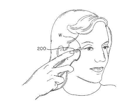
28 FIG. 1 is a top perspective view of a user massaging
29 her face with the preferred embodiment. is shown
Iron 200
;0 in use by a us er. Iron 200 is applied to areas a user'
of s
;i ?-ace ~f~here nkles W are located, such a user's
wri as around
;2 eyes. Use in other locations of a user's face possible
is
6
CA 02301110 2000-02-16
1 due to the specialized shape of the spoon shaped heating
2 surface .
3 FIG. 2 is a side elevation view of the iron. Spoon
4 shaped heating surface 240 is attached to the handle 205.
Recess 210 in handle 205 allows for ease of holding. Handle
6 205 is ergonomically shaped allowing a user to more
7 effectively control the manipulation of the spoon shaped
8 heating surface. For example, placement of a user's palm
9 upon the back of handle 205 results in greater leverage for
applying pressure to a user's facial features, in
11 particular, wrinkles. Electrical contact 215 provides the
12 connection between the charger base (shown in FIG. 4) and
13 the rechargeable batteries contained within the handle 205.
14 FIG. 3 is a bottom plan view of the iron. Spoon shaped
heating surface 240 it attached at one end of handle 205.
16 Spoon shaped heating surface 240 may comprise any heat
17 conductive material, including metal and plastic, known in
18 the art. It may also comprise metal impregnated plastic,
19 also known in the art. Spoon shaped heating surface 240
generally describes any solid section of an elliptically
21 shaped solid, the convex surface of the solid comprising the
22 spoon shaped heating surface. The section may also be oval
23 or spherical. In the preferred embodiment, the spoon shaped
24 surface comprises a narrower end and a wider end, in a form
which may be described in part as "egg-shaped", each being
26 convex, thereby allowing application of the surface to a
27 wide variety of a user's facial features. For ease of
28 reference, and not by way of limitation, reference to the
29 described surface shall be to the "spoon shaped heating
surface". Electrical contacts 215 and 230 provide the
;i connection between the charger (not shown) and tire
32 rechargeable batteries in the handle 205 as shown in FIG. 8.
7
CA 02301110 2000-02-16
( If the red LED 220 on FIG. 2, on the iron is illuminated,
2 this indicates, the batteries are discharging to heat the
3 spoon shaped:heating surface. It takes approximately 40
4 seconds for the spoon shaped heating surface 240 to reach
the operating temperature of 98°F to 120°F. The preferred
6 embodiment operates in the range of 108° F to 112° F. The
7 electronic circiut described in FIG. 9 controls the
8 temperature of the spoon shaped heating surface to
9 approximately plus or minus 2° F. The current to the heater
element is 650 mA to 750 mA. Three AA batteries, 3/4 size -
11 known in the art, should maintain this heat for up to 30
12 minutes. The heat in the spoon shaped surface is
13 thermostatically controlled by a thermostat as shown in FIG.
14 9. Once use of the iron is completed, the iron is returned
to the charger for recharging of the batteries to full
16 charge .
17 FIG. 4 is a perspective view of the preferred
18 embodiment. Iron 200 is received by charger 410.
19 Electrical cord 415 is used to connect charger 410 to any
standard 120V AC supply. Electrical cord 415 may comprise
21 any plug type necessary to accommodate the electrical system
22 in the country of use, for example, 220V in Europe. Contour
23 420 allows the iron 200, having a co-operating contoured
24 shape, to be received by charger 410. The charger 410 is
plugged into a standard 120V outlet. When the iron is
26 placed in the charger, the quick charge of the iron
27 rechargeable batteries occurs. The rechargeable batteries
28 typically consist of 3 P.~1 batteries. The red LED in the
29 charger base, see FIG. 6, illuminates as the batteries in
t_l~e iron are being recharged. The current from the charger
3t bass to the iron batteries is 80 to 120 mA. After 3-5 hours
32 the batteries are completely charged. Once the charging is
s
CA 02301110 2000-02-16
t
I complete the red LED turns off and the green LED
2 illuminates. The charger 410 is then delivering 0 mA to the
3 iron batteries. If the iron 200 is removed and used and
4 returned to the charger, the charger will reactivate at 80
S mA. The red LED will illuminate for as long as charging
6 takes. The green LED will then illuminate again once the
7 batteries are recharged, indicating the iron ready for use.
8 FIG. 5 is a top plan view of the preferred embodiment.
9 Iron 200 is received by charger 410. AC power cord 415
allows connection to a 120V wall socket. Red LED 220
11 illuminates to indicate the spoon shaped heating surface is
12 heating.
13 FIG. 6 is a top plan view of the charger. Charger 410
14 has two electrical contacts 610 and 615 which electrically
connect to contacts 215 and 230 in FIG. 3 to allow charging
16 of the rechargeable batteries. Recess 620 receives the
17 spoon shaped heating surface when the iron (n.ot shown) is
18 placed in the charger 410. Operation of green LED 625 and
19 red LED 630 are described in FIG. 4.
FIG. 7 is a side elevation view of the charger 410
21 without the iron.
22 FIG. 8 is a side elevation cut-away view of the
23 preferred embodiment. Contained within iron 200 are
24 rechargeable batteries 805. Red LED 220 illuminates when
the heating element 800, which is connected to the spoon
26 shaped heating surface 240, is operating. Electrical
27 contact 230 on the iron 200 contacts electrical contact 610
28 on the charger 410. This allows the batteries 805 to be
29 recharged while the iron is in the charger. The circuitry
for charging the iron and controlling the operation of the
31 iron are set= forth in FIGS. 9 and 10. Charger electronics
32 820, known in the art, are contained within' charger 410.
9
CA 02301110 2000-02-16
I Iron electronics 830 as described in FIG. 9 are contained
within iron 200.
3 FIG. 9 i,s an electrical schematic drawing of the iron
4 for the invention. Contacts 215 and 230 are described in
FIG. 3. Rechargeable batteries 905 are in series with
6 switch 910. Relay 915 causes relay contacts to close when
7 the iron is placed in the charger. Magnetic reed switch 920
8 turns on the heater when the iron is removed from the
9 charger. Magnetic reed switch 920 cooperates with magnet
840 on FIG. 8, contained within the charger. Resistor 935
11 protects op amp 950. Switch 920 closes the circuit to op
12 amp 950. Resistors 925, 930, 940 and 945 determine the
13 voltage delivered to the inverting and non-inverting inputs
14 of op amp 950. Output from op amp 950 determines the state
of transistor 960. The heater circuit comprises. resistor
16 955, thermistor 970 and red LED 965. When the iron is being
17 recharged in the charger, transistor 960 opens the heater
18 circuit. When the iron is removed from the charger, relay
19 915 closes switch 910 thereby providing a voltage of 3.6 V
across the circuit. This causes op amp 950 to output a
21 voltage to transistor 960, which changes state and closes
22 the heater circuit. Once the heater circuit is closed,
23 current flows through thermistor 970 and red LED 965 thereby
24 heating the spoon shaped heating surface. Red LED 965
illuminates when thermistor 970 is operating. Once the
26 voltage delivered to the circuit by the batteries reaches a
27 predetermined level, transistor 960 changes state and opens
28 the heating circuit.
29 FIG. 10 is an electrical schematic drawing of the
charger for the invention. AC power cord 1005 is connected
to rectifier bridge 1015 through transformer 1010.
32 Rectifier bridge 1015 rectifies the AC signal to a DC
i0
CA 02301110 2000-02-16
t signal. Capacitor 1020 smoothes the rectified output
2 waveform from .rectifier bridge 1015. Red LED 1025 is in
3 series with resistor 1030. Green LED 1040 is in series with
4 resistor 1050. Resistor 1035 is in parallel with red LED
1025 and resistor 1030. While the charger is recharging the
6 iron, red LED 1025 is illuminated. Current flows through
7 SCR 1045 to contact 615 when the iron is in the charger. As
8 charging is completed, the voltage across contacts 615 and
9 610 decreases until SCR 1045 changes state. Variable
resistor 1060 determines the resistance between contacts 615
11 and 610. Transistor 1055 controls the value of variable
12 resistor 1060. This in turn short circuits the charging
13 current which eliminates the charging current through the
14 iron. Once charging is complete the red LED 1025 goes out
and green LED 1040 is illuminated.
16 FIG . 11 is a side view of an alternate embodiment . In
17 this alternate embodiment, an electric cord 1100 is used to
18 plug the iron 1200 directly into a 120V outlet. The iron is
19 used while it is plugged into the outlet. The heating
element is connected in series with a thermostat. The
21 heating element is heated to and maintained at 108° to 120°F.
22 FIG. 12 is a side view of an alternate embodiment.
23 Recharger 1300 is plugged into a 120V outlet. It is
24 connected to iron 1220 by a plug 1210. Plug 1210 is
disconnected once the rechargeable batteries are charged.
26 The rechargeable batteries are 6V and are known in the art .
27 The iron circuit is as shown in FIG. 9. In yet another
28 alternate embodiment, the wall unit 1300 comprises a
29 transformer and rectifier circuit which provides a low
voltage output to the iron 1220. A thermostat contained
31 within the iron maintains the temperature of the heat-v:zg
32 surface at 108 to 120 °F.
CA 02301110 2000-02-16
I FIG. 13 is a schematic depicting an alternate
2 embodiment showing a three position switch. Three-position
3 switch 1300, known in the art, is connected into the circuit
4 in FIG.9 to operate in co-operation with magnetic reed
switch 920 and relay 915.
6 Switch 1300 may be placed in one of three positions. In
7 position 1, the invention is placed in the charger 410 for
8 battery recharging. In position 1, thermistor 970 is
9 activated upon removal from the charger, as described above
in FIG. 9.
11 In position 2, thermistor 970 is activated regardless
12 of the status or location of the invention. This is a result
13 of switch 1300 closing a circuit around rel-ay 915 and
14 magnetic reed switch 920, thereby directly activating
thermistor 970. In this position 2, a user de-activates the
16 invention by returning the switch 1300 to position 1, for
17 return to the charger, or position 3 as described below.
18 In position 3, the thermistor or heating element
19 circuit is "opened" so that it is not possible for the
thermistor to be activated. This is accomplished by switch
21 1300 opening the circuit connection to ground, thereby
22 preventing activation of the thermistor 970. This allows a
23 user to store the invention, without it being in the
24 charger, with fully charged batteries for use at a later
time, for example, at a location where the charger is not
26 available. To use at a later time, a user simply moves
27 switch 1300 from position 3 to position 2. Once the user has
28 completed use of the invention, the user places the switch
29 in position 3 to de-activate the thermistor circuit; or to
position 1 with the return of the facial iron to the charger
31 base for re-charging the batteries as described above.
I2
CA 02301110 2000-02-16
i;.
i Although the present invention has been described with
2 reference to preferred embodiments, numerous modifications
3 and variations can be made and still the result will come
4 within the scope of the invention. No limitation with
respect to the specific embodiments disclosed herein is
6 intended or should be inferred.
I3
CA 02301110 2000-02-16
INFORMATION DISCLOSURE STATEMENT
2 U.S. Pat;. No. 5,746,702 (1998) to Gelfgat et al.
3 discloses an~ improvement for devices that provide local
4 massage of the facial skin for improvement of the
effectiveness of the massage while making the device more
6 ergonomic.
7 U.S. Pat. No. 5,709,705 (1998) to Belcher discloses the
8 reduction of facial wrinkles by rolling the face and scalp
9 with implements having free wheeling rollers.
U.S. Pat. No. 5,582,585 (1996) to Nash-Morgan discloses
11 a disposable adhesively engagable neck and facial wrinkle
12 gathering device.
_ 13 U.S. Pat. No. 5,501,646 (1996) to Miller discloses a
14 jaw and neck muscle exercise apparatus which includes a
spring-loaded support arm attached to a soft chin support on
16 one end and to a chest plate on the other end.
17 U.S. Pat. No. 5,458,561 (1995) to Schweisfurth
18 discloses a massage device for the rolling massage of skin
19 areas and reflex zones of the human body which includes a
shaft mounted on a handle and massage rings or rolling
21 bodies which are freely rotatably mounted on the shaft.
22 U.S. Pat. No. 5,218,955 (1993) to Gueret discloses a
23 massage device which is adapted to be applied to the skin.
24 U.S. Pat. No. 4,892,092 (1990) to Klein discloses a
2S facial mask for use in effecting isometric toning of facial
26 muscles.
27 U.S. Pat. No. 4,787,373 (1988) to Vogel discloses a
28 facial ironer. The facial ironer apparatus includes a
i
CA 02301110 2000-02-16
housing which holds a heating elemenr_ having a base and a
2 head. There is an electrical cord connecting
the apparatus
3 to a conventional AC electrical outlet. There is a
cord
4 thermostatic switch in the housing for maintaining the
temperature of the heating element at a predetermined
6 setting. The facial ironer i tself demountably attached
is
7 to the head of the heating element. The facial ironer
8 includes a triangular-shaped soleplate.
The soleplate
is
9 heated by the transfer of heat from the heating element.
U.S. Pat. No. 4,291,685 (1981) to Taelman discloses a
11 therapeutic heat and cosmetic applicator. A cosmetologist
12 cleans the skin with unscented makeup remover and lotions.
13 Then a lubricant is applied with a small hot iron to soften
14 the pores. This face ironing is followed by a herbal or
seaweed steam facial, manual and deep-pore cleaning.
16 U.S. Pat. No. 4,189,141 (1980) to Rooney discloses a
17 mask which completely covers the face and which has pockets
18 in which weights may be placed while the facial muscles are
19 exercised.
U.S. Pat. No. 3,911,909 (1975) to Di Matto discloses a
21 facial wrinkle remover.
22 U.S. Pat. No. 3,507,493 (1970) to Robins discloses an
23 eye and forehead area muscle exerciser in which a portion of
24 the face is covered by the device to hold the facial muscles
against movement.
2G
~ I~