Note: Descriptions are shown in the official language in which they were submitted.
CA 02301123 1999-09-29
WO 99/14415 PCTIUS98/I9150
NONWOVEN BONDING PATTERNS PRODUCING FABRICS WITH IMPROVED
The present invention relates to the field of nonwoven fabrics like those
produced by
the meltblowing and spunbonding processes. Such fabrics are used in a myriad
of
io different products such as garments, personal care products, infection
control products,
outdoor fabrics and protective covers.
is Nonwoven fabrics produced by the meltblowing and spunbonding process have
found great utility in many diverse applications from car and boat covers to
incontinence
products. Different attributes or properties of the fabric are required
depending on the
application. A car cover, for example, must have great tensile strength and
resistance to
ultraviolet radiation, while a feminine hygiene product must exhibit great
absorbency and
a o softness. Developing just the right combination of properties for the
application is a complex
task requiring the focused attention of many highly qualified individuals.
The bonding pattern used in either bonding the fibers of the nonwoven fabric
to itself
or in bonding the nonwoven fabric to other material layers can cause great
changes in the
fabric propert'es. Bonding patterns with large bond areas, for example, tend
to make a
CA 02301123 1999-09-29
WO 99/14415 PCT/US98119150
strongly bonded but rough feeling fabric. Those with small bond areas tend to
make soft
feeling but very weak fabric.
Various attempts have been made at overcoming the disadvantage seemingly
inherent in higher bond areas, i.e. decreased softness. One such attempt is
taught in US
Patent 5,620,779 to Levy and McCormack and is a nonwoven fabric with a bond
pattern
having a certain required spacing ratio which is then stretched to produce
ribs.
A number of treatments have also been developed to soften nonwoven fabrics
such
as multiple washings and chemical treatments.
There remains a need, however, for an unribbed fabric without chemical
treatments
to having good bonding strength (i.e. tensile strength and abrasion
resistance) yet also having
good fabric softness without excessive bonding area.
Accordingly, it is an object of this invention to provide a nonwoven fabric
with a
bonding area comparable to fabrics bonded with known patterns yet having
greater softness
and comparable or better tensile strength and abrasion resistance.
The objects of the invention are met by a thermal bonding pattern for nonwoven
fabric comprising a pattern having an element aspect ratio between about 2 and
about 20
z o and an unbonded fiber aspect ratio of between about 3 and about 10. It has
been
unexpectedly found that such a fabric has a higher abrasion resistance and
strength than
a similar fabric bonded with different bond patterns. In alternative
embodiments, the
fabric may be perforated or apertured by stretching after bonding according to
known
techniques.
2
CA 02301123 1999-09-29
WO 99114415 PCT/US98/19150
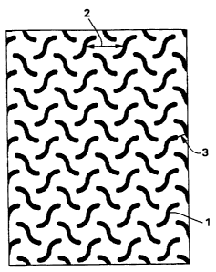
Figure 1 is a drawing of a bonding pattern satisfying the requirements of this
s invention and called the S-weave pattern.
Figure 2 is a drawing of a bonding pattern according to US Patent 3,855,046
known as an Expanded Hansen-Pennings or EHP pattern.
Figure 3 is a drawing of a bonding pattern known in the art as a wire weave
pattern.
io Figure 4 is a drawing of a pattern according to US Patent Application
08/754,419
known as a Point Unbonded Pattern or PUB.
i5 "Hydrophilic" describes fibers or the surfaces of fibers which are wetted
by the
aqueous liquids in contact with the fibers. The degree of wetting of the
materials can, in
turn, be described in terms of the contact angles and the surface tensions of
the liquids
and materials involved. Equipment and techniques suitable for measuring the
wettability
of particular fiber materials or blends of fiber materials can be provided by
a Cahn
z o SFA-222 Surface Force Analyzer System, or a substantially equivalent
system. When
measured with this system, fibers having contact angles less than 90°
are designated
"wettable" or hydrophilic, while fibers having contact angles equal to or
greater than 90°
are designated "nonwettable" or hydrophobic.
"Layer" when used in the singular can have the dual meaning of a single
element
zs or a plurality of elements.
3
CA 02301123 1999-09-29
WO 99/14415 PCT/US98/19150
As used herein the term "nonwoven fabric or web" means a web having a
structure
of individual fibers or threads which are interlaid, but not in an
identifiable manner as in a
knitted fabric. Nonwoven fabrics or webs have been formed from many processes
such as
for example, meltblowing processes, spunbonding processes, and bonded carded
web
s processes. The basis weight of nonwoven fabrics is usually expressed in
ounces of material
per square yard (osy) or grams per square meter (gsm) and the fiber diameters
useful are
usually expressed in microns. (Note that to convert from osy to gsm, multiply
osy by 33.91 ).
As used herein the term "microfibers" means small diameter fibers having an
io average diameter not greater than about 75 microns, for example, having an
average
diameter of from about 0.5 microns to about 50 microns, or more particularly,
microfibers
may have an average diameter of from about 2 microns to about 40 microns.
Another
frequently used expression of fiber diameter is denier, which is defined as
grams per 9000
meters of a fiber and may be calculated as fiber diameter in microns squared,
multiplied by
15 the density in grams/cc, multiplied by 0.00707. A lower denier indicates a
finer fiber and a
higher denier indicates a thicker or heavier fiber. For example, the diameter
of a
polypropylene fiber given as 15 microns may be converted to denier by
squaring, multiplying
the result by .89 g/cc and multiplying by .00707. Thus, a 15 micron
polypropylene fiber has
a denier of about 1.42 (152 x 0.89 x .00707 = 1.415). Outside the United
States the unit of
z o measurement is more commonly the "tex", which is defined as the grams per
kilometer of
fiber. Tex may be calculated as denier/9.
"Spunbonded fibers" refers to small diameter fibers which are formed by
extruding
molten thermoplastic material as filaments from a plurality of fine, usually
arcular capillaries
of a spinneret with the diameter of the extruded filaments then being rapidly
reduced as by,
25 for example, in US Patent 4,340,563 to Appel et al., and US Patent
3,692,618 to Dorschner
4
CA 02301123 1999-09-29
WO 99/14415 PCT/US98/19150
et al., US Patent 3,802,817 to Matsuki et al., US Patents 3,338,992 and
3,341,394 to
Kinney, US Patent 3,502,763 to Hartman, and US Patent 3,542,615 to Dobo et al.
Spunbond fibers are generally not tacky when they are deposited onto a
collecting surface.
Spunbond fibers are generally continuous and have average diameters (from a
sample of at
s least 10) larger than 7 microns, more particularly, between about 10 and 20
microns.
"Meltbiown fibers" means fibers formed by extruding a molten thermoplastic
material
through a plurality of fine, usually circular, die capillaries as molten
threads or filaments into
converging high velocity, usually hot, gas (e.g. air) streams which attenuate
the filaments of
molten thermoplastic material to reduce their diameter, which may be to
microfiber diameter.
to Thereafter, the meltblown fibers are carried by the high velocity gas
stream and are
deposited on a collecting surface to form a web of randomly disbursed
meltblown fibers.
Such a process is disclosed, for example, in US Patent 3,849,241. Meltblown
fibers are
microfibers which may be continuous or discontinuous, are generally smaller
than 10
microns in average diameter, and are generally tacky when deposited onto a
collecting
i5 surface.
As used herein, the term "coform" means a process in which at least one
meltblown
diehead is arranged near a chute through which other materials are added to
the web while
it is forming. Such other materials may be wood pulp, superabsorbent
particles, cellulose or
staple fibers, for example. Coform processes are shown in commonly assigned US
Patents
20 4,818,464 to Lau and 4,100,324 to Anderson et al. Webs produced by the
coform process
are generally referred to as coform materials.
"Conjugate fibers" refers to fibers which have been formed from at least two
polymer
sources extruded from separate extruders but spun together to form one fiber.
Conjugate
fibers are also sometimes referred to as multicomponent or bicomponent fibers.
The
2 s polymers are usually different from each other though conjugate fibers may
be
CA 02301123 1999-09-29
WO 99/14415 PCT/US98/19150
monocomponent fibers. The polymers are arranged in substantially constantly
positioned
distinct zones across the cross-section of the conjugate fibers and extend
continuously
along the length of the conjugate fibers. The configuration of such a
conjugate fiber may be,
for example, a sheath/core arrangement wherein one polymer is surrounded by
another or
may be a side by side arrangement, a pie arrangement or an "islands-in-the-
sea"
arrangement. Conjugate fibers are taught, for example, in US Patent 5,382,400
to Pike et
al. For two component fibers, the polymers may be present in ratios of 75125,
50150, 25/75
or any other desired ratios. The fibers may also have shapes such as those
described in
US Patents 5,277,976 to Hogle et al. which describes fibers with
unconventional shapes.
io "Biconstituent fibers" refers to fibers which have been formed from at
least two
polymers extruded from the same extruder as a blend. The term "blend" is
defined below.
Biconstituent fibers do not have the various polymer components arranged in
relatively
constantly positioned distinct zones across the cross-sectional area of the
fiber and the
various polymers are usually not continuous along the entire length of the
fiber, instead
i5 usually forming fibrils or protofibrils which start and end at random.
Biconstituent fibers are
sometimes also referred to as multiconstituent fibers. Fibers of this general
type are
discussed in, for example, US Patent 5,108,827 to Gessner.
As used herein "thermal point bonding" involves passing a fabric or web of
fibers to
be bonded between a heated calender roll and an anvil roll. The calender roll
is usually,
a o though not always, patterned in some way so that the en~re fabric is not
bonded across its
entire surface, and the anvil roll is usually flat. As a result, various
patterns for calender rolls
have been developed for functional as well as aesthetic reasons. One example
of a pattern
has points and is the Hansen-Pennings or "H&P" pattern with about a 30% bond
area with
about 200 pins/square inch as taught in U.S. Patent 3,855,046 to Hansen and
Pennings.
25 The H&P pattern has square point or pin bonding areas. Another typical
point bonding
CA 02301123 1999-09-29
WO 99/14415 PCT/US98/19150
pattern is the expanded Hansen-Pennings or "EHP" bond pattern which produces a
15%
bond area. Another typical point bonding pattern designated "714" has square
pin bonding
areas wherein the resulting pattern has a bonded area of about 15%. Other
common
patterns include a diamond pattern with repeating and slightly offset diamonds
with about a
s 16% bond area and a wire weave pattern looking as the name suggests, e.g.
like a window
screen, with about an 18% bond area. Typically, the percent bonding area
varies from
around 10% to around 30% of the area of the fabric laminate web. As in well
known in the
art, the spot bonding holds the laminate layers together as well as imparts
integrity to each
individual layer by bonding filaments and/or fibers within each layer.
Zo As used herein "pattern unbonded" or interchangeably "point unbonded" or
"PUB",
means a fabric pattern having continuous thermally bonded areas defining a
plurality of
discrete unbonded areas. The fibers or filaments within the discrete unbonded
areas are
dimensionally stabilized by the continuous bonded areas that encircle or
surround each
unbonded area, such that no support or backing layer of film or adhesive is
required. The
i5 unbonded areas are specifically designed to afford spaces between fibers or
filaments
within the unbonded areas. A suitable process for forming the pattern-unbonded
nonwoven material of this invention includes providing a nonwoven fabric or
web,
providing opposedly positioned first and second calender rolls and defining a
nip
therebetween, with at least one of said rolls being heated and having a
bonding pattern on
a o its outermost surface comprising a continuous pattern of land areas
defining a plurality of
discrete openings, apertures or holes, and passing the nonwoven fabric or web
within the
nip formed by said rolls. Each of the openings in said roll or rolls defined
by the
continuous land areas forms a discrete unbonded area in at least one surface
of the
nonwoven fabric or web in which the fibers or filaments of the web are
substantially or
as completely unbonded. Stated alternatively, the continuous pattern of land
areas in said roll
CA 02301123 1999-09-29
WO 99/14415 PCT/US98/19150
or rolls forms a continuous pattern of bonded areas that define a plurality of
discrete
unbonded areas on at least one surface of said nonwoven fabric or web.
Alternative
embodiments of the aforesaid process includes pre-bonding the nonwoven fabric
or web
before passing the fabric or web within the nip formed by the calender rolls,
or providing
s multiple nonwoven webs to form a pattern-unbonded laminate. The point
unbonded
pattern and process are described in US Patent Application 08/754,419 and an
example
may be seen in Fig. 4.
As used herein, the term "element aspect ratio" refers to the ratio between
the
length of an element or pin in a bonding pattern to the width of the same
element,
io calculated as length of an element measured along its centerline divided by
width of the
element.
As used herein, the term "unbonded fiber aspect ratio" refers to the ratio
between
the longest and shortest distances between elements or pins of a bond pattern
within a
repeating pattern. This ratio is calculated as the longest distance divided by
the shortest
i5 distance.
As used herein, the terms "necking" or "neck stretching" interchangeably refer
to a
method of elongating a nonwoven fabric, generally in the machine direction, to
reduce its
width in a controlled manner to a desired amount. The controlled stretching
may take place
under cool, room temperature or greater temperatures and is limited to an
increase in
a o overall dimension in the direction being stretched up to the elongation
required to break the
fabric, which in most cases is about 1.2 to 1.4 times. When relaxed, the web
retracts toward
its original dimensions. Such a process is disclosed, for example, in US
Patent 4,443,513 to
Meitner and Notheis, US Patents 4,965,122, 4,981,747 and 5,114,781 to Morman
and US
Patent 5,244,482 to Hassenboehler Jr. et al.
8
CA 02301123 1999-09-29
WO 99/14415 PCT/US98/19150
As used herein, the term "garment" means any type of non-medically oriented
apparel which may be wom. This includes industrial work wear and coveralls,
undergarments, pants, shirts, jackets, gloves, socks, and the like.
As used herein, the term "infection control product" means medically oriented
items
s such as surgical gowns and drapes, face masks, head coverings like bouffant
caps, surgical
caps and hoods, footwear like shoe coverings, boot covers and slippers, wound
dressings,
bandages, sterilization wraps, wipers, garments like lab coats, coveralls,
aprons and jackets,
patient bedding, stretcher and bassinet sheets, and the like.
As used herein, the term "personal care product' means diapers, training
pants,
io absorbent underpants, adult incontinence products, and feminine hygiene
products.
As used herein, the term "protective cover" means a
cover for vehicles such as cars, trucks, boats, airplanes, motorcycles,
bicycles, golf carts,
etc., covers for equipment often left outdoors like grills, yard and garden
equipment
(mowers, roto-tillers, etc.) and lawn furniture, as well as floor coverings,
table cloths and
is picnic area covers.
As used herein, the term "outdoor fabric" means a fabric which is primarily,
though
not exclusively, used outdoors. Outdoor fabric includes fabric used in
9
CA 02301123 1999-09-29
WO 99/14415 PCT/US98/19150
protective covers, camper/trailer fabric, tarpaulins, awnings, canopies,
tents, agricultural
fabrics and outdoor apparel such as head coverings, industrial work wear and
coveralls,
pants, shirts, jackets, gloves, socks, shoe coverings, and the like.
s TEST METHODS
Grab Tensile test: The grab tensile test is a measure of breaking strength and
elongation or strain of a fabric when subjected to unidirectional stress. This
test is known in
the art and conforms to the specifications of Method 5100 of the Federal Test
Methods
to Standard 191A. The results are expressed in pounds or grams to break and
percent
stretch before breakage. Higher numbers indicate a stronger, more stretchable
fabric. The
term "load" means the maximum toad or force, expressed in units of weight,
required to
break or rupture the specimen in a tensile test. The term "total energy" means
the total
energy under a load versus elongation curve as expressed in weight-length
units. The term
i5 "elongation" means the increase in length of a specimen during a tensile
test. The grab
tensile test uses two clamps, each having two jaws with each jaw having a
facing in contact
with the sample. The clamps hold the material in the same plane, usually
vertically,
separated by 3 inches (76 mm) and move apart at a specified rate of extension.
Values for
grab tensile strength and grab elongation are obtained using a sample size of
4 inches (102
z o mm) by 6 inches (152 mm), with a jaw facing size of 1 inch (25 mm) by 1
inch; and a
constant rate of extension of 300 mm/min. The sample is wider than the clamp
jaws to give
results representative of effeclwe strength of fibers in the clamped width
combined with
additional strength contributed by adjacent fibers in the fabric. The specimen
is clamped in,
for example, a Sintech 2 tester, available from the Sintech Corporation, 1001
Sheldon Dr.,
z5 Cary, NC 27513, an Instron Model TM, available from the Instron
Corporation, 2500
*rB
CA 02301123 1999-09-29
WO 99/I4415 PCT/US98/19150
Washington St., Canton, MA 02021, or a Thwing-Albert Model INTELLECT II
available from
the Thwing-Albert Instrument Co., 10960 Dutton Rd., Phila., PA 19154. This
closely
simulates fabric stress conditions in actual use. Results are reported as an
average of three
specimens and may be performed with the specimen in the cross direction (CD)
or the
s machine direction (MD).
Strip Tensile: The strip tensile test is similar to the grab tensile and
measures the
peak and breaking loads and peak and break percent elongations of a fabric.
This test
measures the load (strength) in grams and elongation in percent. In the strip
tensile test,
two clamps, each having finro jaws with each jaw having a faang in contact
with the sample,
io hold the material in the same plane, usually vertically, separated by 3
inches and move
apart at a specified rate of extension. Values for strip tensile strength and
strip elongation
are obtained using a sample size of 3 inches by fi inches, with a jaw faang
size of 1 inch
high by 3 inches wide, and a constant rate of extension of 300 mmlmin. The
Sintech 2
tester, available from the Sintech Corporation, 1001 Sheldon Dr., Cary, NC
27513, the
i5 Instron Model TM, available from the Instron Corporation, 2500 Washington
St., Canton, MA
02021, or a Thwing-Albert Model INTELLECT II available from the Thwing-Albert
Instrument
Co., 10960 Dutton Rd., Phila., PA 19154 may be used for this test. Results are
reported as
an average of three specimens and may be performed with the specimen in the
cross
direction (CD) or the machine direction (MD).
ao Peel test: In peel or delamination testing a laminate is tested for the
amount of
tensile force which will pull the layers of the laminate apart. Values for
peel strength are
obtained using a specified width of fabric, clamp jaw width and a constant
rate of extension.
For samples having a film side, the film side of the specimen is covered with
masking tape
or some other suitable material in order to prevent the film from ripping
apart during the test.
25 The masking tape is on only one side of the laminate and so does not
contribute to the peel
CA 02301123 1999-09-29
WO 99/14415 PCT/US98/19150
strength of the sample. This test uses two clamps, each having two jaws with
each jaw
having a facing in contact with the sample, to hold the material in the same
plane, usually
vertically, separated by 2 inches to start. The sample size is 4 inches wide
by as much
length as necessary to delaminate enough sample length. The jaw facing size is
1 inch high
s by at least 4 inches wide, and the constant rate of extension is 300 mm/min.
The sample is
delaminated by hand a sufficient amount to allow it to be clamped into
position and the
clamps move apart at the specfied rate of extension to pull the laminate
apart. The sample
specimen is pulled apart at 180° of separation between the two layers
and the peel strength
reported as an average of peak load in grams. Measurement of the force is
begun when 16
io mm of the laminate has been pulled apart and continues until a total of 170
mm has been
delaminated. The Sintech 2 tester, available from the Sintech Corporation,
1001 Sheldon
Dr., Cary, NC 27513, the Instron Model TM, available from the Instron
Corporation, 2500
Washington St., Canton, MA 02021, or the Thwing-Albert Model INTELLECT II
available
from the Thwing-Albert Instrument Co., 10960 Dutton Rd., Phila., PA 19154, may
be used
15 for this test. Results are reported as an average of three specimens and
may be performed
with the specimen in the cross direction (CD) or the machine direction (MD).
Martindale Abrasion test: This test measures the relative resistance to
abrasion of a
fabric. The test results are reported on a scale of 1 to 5 with 5 being the
least wear and 1
the most, after 120 cycles with a weight of 1.3 pounds per square inch. The
test is carried
a o out with a Martindale Wear and Abrasion Tester such as model no. 103 or
model no. 403
available from James H. Heal & Company, Ltd. of West Yorkshire, England. The
abradant
used is a 36 inch by 4 inch by 0.05 thick silicone rubber wheel reinforced
with fiber glass
having a rubber surface hardness 81A Durometer, Shore A of 81 plus or minus 9.
The
abradant is available from Flight Insulation inc., a distributor for
Connecticut Hard Rubber,
z s 925 Industrial Park, NE, Marietta, GA 30065.
12
CA 02301123 1999-09-29
WO 99/14415 PCT/US98/19150
Handle-O-Meter: The softness of a nonwoven fabric may be measured according to
the "Handle-O-Meter" test. The test used herein is the INDA standard test 1st
90.0-75 (R
82) with two modifications: 1 ) the specimen size was 4 inches by 4 inches and
2} five
specimens were tested rather than two. The test was carried out on Handle-O-
Meter model
number 211-5 from the Thwing-Albert Instrument Co., 10960 Dutton Road, Phila.
PA 19154.
The Handle-O-Meter reading is on a scale of 1 to 5.
Hydrohead: A measure of the liquid barrier properties of a fabric is the
hydrohead
test. The hydrohead test determines the height of water (in mbars) which the
fabric will
support before a predetermined amount of liquid passes through. A fabric with
a higher
to hydrohead reading indicates it has a greater barrier to liquid penetration
than a fabric with a
lower hydrohead. The hydrohead test is performed according to Federal Test
Standard
191 A, Method 5514.
Many different thermal bonding patterns have been developed for nonwoven
fabrics in order to give them integrity for further processing into finished
materials, for
bonding to other materials (e.g. nonwovens and films) and to impart particular
visual
markers. Some patterns for sterile wrap applications, for example, provide
indicators to
a o help show where the fabric should be folded. Patterns for diapers and
wipes can include
"baby objects" such as bears, trains, etc. More utilitarian patterns have been
developed
for applications such as car covers and oil absorption materials.
One recently developed pattern is known as a point unbonded or PUB pattern and
includes unbonded fabric surrounded 100 percent by bond area, an example of
which is
shown in Fig. 4. This pattern generally may have a bond area of from about 25
to about
13
CA 02301123 1999-09-29
WO 99/14415 PCT/US98/19150
50 percent. The complete surrounding of an unbonded area gives this pattern
good
abrasion resistance and nonwoven fabrics having this pattern have found
utility as, for
example, the "loop" in hook and loop fastening systems. Such fabrics may be
found in the
landing zone on some Huggies~ diapers. The complete surrounding of an unbonded
area is believed to significantly reduce fiber mobility by tying down all
loose ends within a
small area. While useful for many applications requiring toughness, fabrics
with this
pattern can be somewhat stiff.
An older pattern is that known as an Expanded Hansen-Pennings or "EHP" bond
pattern. The EHP patterns has a bond area generally from about 10 to about 30
percent, an
io example of which is shown in Fig. 2. Higher bond areas are possible but
usually result in
stiff fabrics unsuitable for many applications. The EHP pattern does not
completely
surround an unbonded area and so fiber mobility and softness are greater than
in a PUB
fabric, however abrasion resistance and strength are lower than a PUB fabric
at the same
bond area.
~.5 In order to avoid the trade-off between abrasion resistance and softness
seen in the
PUB, EHP and other patterns, the inventors have developed a pattern wherein an
unbonded
area is not completely surrounded by bond area but is surrounded to a large
degree. This
pattern provides sufficient numbers of immobilized fibers to strengthen the
fabric, yet not so
much as to increase stiffness unacceptably.
2 o Testing of fabrics bonded with an example of the inventive pattern (called
by the
inventors °S-weave") and with EHP bonded fabrics showed a surprising
increase in abrasion
resistance and hydrohead with good strength and acceptable softness. Details
of the
fabrics and the testing follow.
14
CA 02301123 1999-09-29
WO 99/14415 PCT/US98/19150
A laminate was produced using a nonwoven layer and a film layer.
The nonwoven layer was a 20 gsm layer of fabric made by a spunbond process
with
2 denier fibers produced from a polypropylene copolymer having about 3.5
weight percent
s ethylene. The copolymer was produced by the Union Carbide Company under the
designation 6D43. The nonwoven fabric so produced was thermally self bonded
with either
the EHP pattern of Figure 2 or the S-weave pattern of Figure 1.
The film was a multilayer film having a bonding layer and an outer layer. The
film
was produced by coextrusion and had an overall basis weight was 58 gsm. The
bonding
i o layer was made from about 55 weight percent SupercoatT"" CaCO~ (available
from English
China Clay of Sylacauga, Alabama, and having a coating of about 1.5 weight
percent of
either stearic or behenic acid to enhance dispersion of the filler), 45 weight
percent Dow
AFFINITY~ EG 8200 low density elastomeric metallocene catalyzed polyethylene
having a
density of 0.87g/cm3 and a melt index at 190°C of 5 g/10 min. The outer
layer was made of
is about 50 weight percent Supercoat"~' CaC03, 45 weight percent DOWLEX~ NG
3310 linear
low density polyethylene having a density of about 0.918 g/cm3 and a melt
index at 190°C
of 3.5 g/10 min., 5 weight percent Dow low density polyethylene 4012, and
about 2000 ppm
of Ciba Geigy's 8900 stabilizer.
The co-extruded film was stretched in the machine direction in a single
stretching
20 operation to about 391 percent of its original length. Prior to stretching,
the film was pre-
heated by passing it around a series of rolls at about 49°C. In the
stretching step, the film
was held back by a slow roll at about 66°C and drawn by a fast roll at
about 21 °C. The
stretched film was then annealed by passing over another roll without
stretching at about
82°C.
CA 02301123 1999-09-29
WO 99/14415 PCT/US98/19150
The stretched film and pre-bonded nonwoven were fed to a thermal point bonder
and laminated together using a heated pattern roll at about 93°C and a
smooth steel anvil
roll at about 88°C with a nip pressure of about 175 pounds per linear
inch. The pattern roll
used a baby objects pattern which imparts about a 15 percent bond area to the
laminate.
s The resulting laminate made with the nonwoven fabric and film had a basis
weight of
about 42 gsm. The laminate with the fabric having an S-weave pattern had an
unsupported
hydrohead of about 95 mbar when 1 drop of water of water emerged on the
opposite side
and an MD peel strength of 226 gms. The laminate with the fabric having an EHP
pattern
had an unsupported hydrohead of about 61 mbar when 1 drop of water emerged on
the
io opposite side and an MD peel strength of about 298 gms. Note that these
results are
averages for three separate measurements.
Samples of the nonwoven fabric (only) from Example 1 were tested for
Martindale
1s abrasion, Handle-o-meter, tensile strength, and grab tensile. The results
are given in Table
1.
16
*rB
CA 02301123 1999-09-29
WO 99/14415 PCTNS98/19150
Table
Bond Basis 1 Handle-O-
Strip
Tensile
Area Weight MD CD Meter
osy grams MD CD
S-weave 17.7 0.65 6717 35497 2.5
EHP 16.8 0.697 4373 20046.7 1.3
1o grab grab Martindale
MD CD Abrasion
pk pk
gm gm scale 1-5
S-weave 5061 3589 5
EHP 3867 2188 3
Comparative Exampj~
As a comparative example, samples of nonwoven fabric (only) made from the same
polymer as in the above Examples and having a rib-knit (RK) pattern according
to US Patent
5,620,779 and wire weave (WW) pattern were tested in the same manner as in
Example 2.
2 o This information is shown below in Table 2.
Table 2
Bond Basis Strip Tensile Handle-O-
Area Weight MD CD Meter
osy grams MD CD
RK 16.5 0.56 3551 3168 3.8 2
W W 18 0.59 4187 3234 7 3.3
grab grab Martindale
3 o MD pk CD pk Abrasion
gm gm scale
1-5
RK 3988 3288 3
WW 2826 3366 4.4
17
CA 02301123 1999-09-29
WO 99/14415 PCTNS98119150
The results from the S-weave examples show an increase in strength and
abrasion
resistance while maintaining acceptable softness. Hydrohead in a laminate form
with film
also was increased. These increases are quite surprising since both the S-
weave and EHP
patterns have about the same bond area, bond density and basis weight.
In alternative embodiments an S-weave patterned fabric or laminate may be
stretched in order to create perforations or apertures in the material
according to, for
example, the neck stretching patents cited above or US Patent 4,588,630 to
Shimalla, US
Patent 3,949,127 to Ostermeier et al, and US Patent 5,628,097 to Benson et al.
which
io involve stretching a fabric after patterning in order to open the fabric at
the bond points.
The S-weave type of pattern is best understood by examining the aspect ratio
of the
elements or pins of the pattern as well as the unbonded fiber aspect ratio.
Turning now to the drawings, note that the lines drawn on Figures 2 and 3 are
for
illustrative purposes only and do not form part of the patterns. The elements
or pins only
Zs form the patterns.
Figure 1 is an example of a pattern fitting the requirements of the invention.
Figure 1
has elements or pins 1 which are identical. Trie pins have a center to center
spacing 2 of
0.143 inches and a minimum spacing 3 of 0.0288 inches. The pins are 0.012
inches wide
and 0.1226 inches long along the centerline.
ao Figure 2 has a pattern of square tapered points 10 with a wide spacing 11
of 0.0664
inches and a narrow spacing 12 of 0.0526 inches. The pins are all 0.037 inches
across.
Figure 3 has identical elongated oval shaped elements 20 which have a width of
21
of 0.016 inches and length 22 of 0.031 inches.
Figure 4 has fibers 30 completely surrounded by bond area 31 which is shown
2 5 diagonally lined.
18
CA 02301123 1999-09-29
WO 99/14415 PCT/US98/19150
The element aspect ratio for the EHP pattern shown in Figure 2 is 1 since the
length
and width of the element are the same, i.e., the bonds are square. The wire
weave pattern
of Figure 3 has elements of length 0.031 inches and width of 0.016 inches for
an element
aspect ratio (0.031/0.016) of about 2. The element aspect ratio for ttte S-
weave pattern
s shown in Figure 1, for example, is 0.1226/0.012 inches or about 10. Ratios
as high as 20
and as low as 2 are believed to work wherein ratios beyond these limits will
suffer from
stiffness (more than 20) or lack of integrity (less than 2). More particularly
a ratio of between
about 7 and 15 is desirable or still more particularly, between about 8 and
12.
Also required is that the unbonded areas of the pattern be suffiaently large.
This
io ensures that enough fibers will be free for use, for example, as a loop
material for a hook
and loop fastening system. This also helps ensure that the fiber will not be
too stiff. In the
case of Figure 2, the unbonded fiber aspect ratio is about 3 and in the case
of Figure 3
about 1.7. The S-weave pattern of Figure 1 has an unbonded fiber aspect ratio
of about 5
as calculated by 0.143/0.0288. Ratios as high as 10 and as low as 3 are
believed to work,
i5 more particularly a ratio of between about 8 and 3 is desirable or still
more particularly,
between about 6 and 4.
The bond area is also important in describing the bond pattern of this
invention since
a highly bonded pattern would be entirely too stiff. The inventors have found
that a bond
area percentage of less than about 30 percent is required, more particularly
befinreen about
a o 10 and 25 percent and still more particularly between about 15 and 20
percent.
Another aspect of the S-weave pattern is the pin density of the pattern. Some
bonding patterns may have pin densities of as much as 500 pins per square
inch, while the
S-weave and EHP patterns are generally in the 50 -200 pin/inz range, more
preferably about
75-150, and, in the Examples, about 100. The patterns of US Patent 5,620,779,
for
a s example, have pin densities in the 200-300 range, and the well known wire
weave pattern
i9
CA 02301123 1999-09-29
WO 99/14415 PCT/US98/19150
usually has a pin density of about 300, even when bonded with approximately
the same
bond area as an S-weave or EHP pattern. The RK pattern and WW patterns of the
Comparative Example had pin densities of about 242 and 302, respectively. Its
believed
that higher pin densities with about the same bond area tie down more fibers,
i.e., reduce
s fiber freeness, and so serve to stiffen a fabric and reduce softness.
The novel S-weave pattern may be used to self bond fabrics and should be
distinguished from patterns made to laminate materials together which are
signficantly
different. The S-weave pattern may be used with any thermally bondable fiber,
monocomponent, biconstituent, conjugate, coform etc.
io The pattern of Figure 1, for example, satisfies the requirements of the
invention and
produces a fabric with abrasion resistance and strength greater than a fabric
bonded with a
like amount of bond area but without the required aspect ratios. The hydrohead
for
nonwoven/film embodiments is also superior to fabrics having similar bond area
but aspect
ratios outside of the invention requirements.
i5 Although only a few exemplary embodiments of this invention have been
described in detail above, those skilled in the art will readily appreciate
that many
modifications are possible in the exemplary embodiments without materially
departing
from the novel teachings and advantages of this invention. Accordingly, all
such
modifications are intended to be included within the scope of this invention
as defined in
a o the following claims. tn the claims, means plus function claims are
intended to cover the
structures described herein as performing the recited function and not only
structural
equivalents but also equivalent structures. Thus although a nail and a screw
may not be
structural equivalents in that a nail employs a cylindrical surtace to secure
wooden parts
together, whereas a screw employs a helical surface, in the environment of
fastening
25 wooden parts, a nail and a screw may be equivalent structures.
CA 02301123 1999-09-29
WO 99/14415 PCT/US98/19150
It should be noted that this patent application is one of a series of
applications
being filed on the same date, having the same assignee, and incorporated
herein by
reference in their entirety. In addition to the instant applications, these
are:
"Stretch-pillowed Bulked Laminate Useful as an Ideal Loop Fastener Component",
inventors: McCormack and Haffner, Attorney docket no. 13520.
"Breathable Barrier Composite Useful as an Ideal Loop Fastener Component",
inventors: McCormack, Haffner and Jackson, Attorney docket no. 13148.
21