Note: Descriptions are shown in the official language in which they were submitted.
CA 02301144 1999-12-13
WO 98158434 PCT/US98/11373
OVERVOLTAGE PROTECTION CIRCUIT
FOR A GENERATING SYSTEM
Technical Field:,
The present invention relates generally to protection circuits and, more
particularly,
to protection circuits that protect connected load equipment against an
overvoltage
condition.
Background Art
Differential protection circuitry is often employed in power supply systems to
sense
and respond to adverse current fault conditions. The protection circuitry is
positioned to
protect a portion of the system referred to in the art as the differential
protection zone and
includes sensors that monitor the current flow at the first and second
boundaries of the
zone. An abnormal current condition within the zone, created, for example, by
a short
circuit, causes the current flow between the zone boundaries to differ. The
sensors, in
response to the sensed differential current, actuate means to mitigate the
fault current
condition. Such protection is especially advantageous where rapid response to
fault
current conditions is crucial. For example, early response to an abnormal
current
condition will often prevent arcing or wire fires which are particularly
hazardous in
locations near the combustible jet fuel tanks aboard an aircraft.
Although differential protection circuits respond to fault current conditions,
they' do
not protect against overvoltage conditions because such conditions do not
typically result
in a differential current between zone boundaries. Therefore, additional
protective circuitry
is typically required to minimize the effects of an overvoltage condition in a
differential
protection zone. Such an overvoltage condition can arise, for example, when a
voltage
regulator in a brushless, synchronous generator fails in a full-on condition,
causing exciter
current to rise substantially above required levels. In a typical aircraft or
aerospace
constant frequency application where load voltage is not to exceed 180 volts
and.arvhere
a variable-frequency machine experiences speed variations over a 2:1 speed
range, a
1
CA 02301144 1999-12-13
WO 98/58434 PCTIUS98I11373
voltage magnitude of 360 volts can be developed when the voltage regulator
fails in the
full-on condition.
Traditional methods of protecting connected load equipment from an overvoltage
condition occurring at the output windings of a generator involve shunting or
otherwise
isolating the generator output windings. Generally, a controlled rectifier
switch is used to
shunt the output current, thereby preventing the connected load equipment from
experiencing the overvoltage. A representative system is described in Jakobs
et al., U.S.
Pat. No. 3,943,408,
Okano et al., U.S. Pat. No. 5,164,874, discloses a shunting circuit operating
in
combination with a fuse. The shunting circuit responds to transient
overvoltage conditions
by shunting the output windings and the fuse responds to the resulting
overcurrent
condition of a longer duration by disconnecting the generator output winding
from the
connected load.
Although the prior art discloses methods for protecting against overvoltage
and
overcurrent conditions, it does not describe a differential protection
function that provides
both overcurrent and overvoltage protection.
summary of the Invention
In accordance with the present invention, overvoltage protection capability is
provided through the action of a differential protection circuit for a power
generating
system.
More particularly, according to one aspect of the present invention, a circuit
that
protects a load coupled to a power supply system includes first and second
differential
current protection sensors that are adapted to sense current magnitudes at
first and
second boundaries of a differential protection zone. The circuit further
includes a control
circuit that responds to the first and second differential current sensors to
disable a
generator of the power supply system in the event that a differential current
condition is
detected. A controllable switching element is cc _ _ led to the conductor at a
point within
the differential protection zone and is further coupled at a second end to a
source of
potential. Means are coupled to the controllable switching element and the
generator for
rendering the controllable switching element conductive in response to a
generator
2
CA 02301144 1999-12-13
WO 98/58434 PCT/US98/11373
overvoltage to connect the generator to the source of potential and thereby
limit load
voltage and cause a differential current condition to arise.
The protective circuit of the present invention utilizes the fault current
sensing
capabilities of a differential protection circuit in combination with a
shunting circuit to
protect a power generating system against an overvoltage condition. The
circuit offers the
combined advantage of protecting attached load equipment from the harmful
effects of an
overvoltage condition while also ensuring rapid deexcitation of the generator.
Such
protection is especially advantageous where rapid response to overvoltage
conditions is
crucial to protect load equipment which could be damaged by overvoltage.
Brief Description of the Drawings
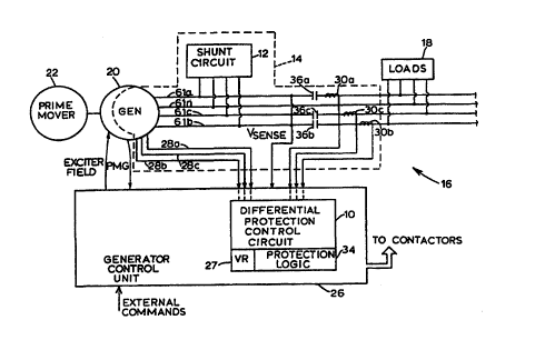
Fig. 1 comprises a block diagram of a power generating system incorporating
the
present invention;
Fig. 2 comprises a combined schematic and block diagram of the generator and
shunt circuit of Fig. 1; and
Fig. 3 comprises a schematic of the shunt circuit of Figs. 1 and 2.
Descr~tion of the Preferred Embodiment
Referring now to Fig. 1, a differential protection control circuit 10 acting
in
combination with a shunt circuit 12 protects a differential protection zone 14
of a power
generating system 18 and one or more connected loads 18. The power generating
system
16 includes a generator 20, preferably of the brushless, synchronous type,
which is
coupled to and driven by a prime mover in the form of an aircraft jet engine
22. The
differential protection control circuit 10 forms a part of a generator control
unit (GCU) 26,
which also includes a voltage regulation (VR) circuit 27 and current limiting
capability.
Referring also to Fig. 3, the boundaries of the differential protection zone
14 are
defined by the locations of the two sets of differential protection sensors
28a-28c, 30a-30c
adapted to sense current magnitudes. Each sensor of the set 28 comprises a
current
transformer sensing current in one of a set of polyphase main armature
windings 32a-32c
of the generator 20. The sensor set 28a-28c is disposed in the generator 20
(as seen in
Fig. 3). Each sensor of the set 30 comprises a current transformer sensing the
current in
3
CA 02301144 1999-12-13
WO 98158434 PCT/US98/11373
the load bus connected to the load(s). The differential protection control
circuit 10 utilizes
the outputs of the current sensors 28a-28c, 30a-30c to monitor current flow
through the
differential protection zone 14. An abnormal current condition caused, for
example, by a
short circuit occurring within the zone boundaries will cause a difference in
the magnitudes
of current sensed at the zone boundaries. Upon sensing a differential current
magnitude,
the differential protection control circuit 10 relays a command signal to the
protection logic
34 of the GCU 26 to open controllable contactors 36a-36c and thereby
disconnect the
generator 20 from the loads) 18. In addition, the voltage regulation circuit
27 is
commanded to deexcite the generator 20 in the fashion noted in greater detail
hereinafter.
Thus, the power generating system 16 is quickly isolated from the loads) in
the event of
a differential fault condition, thereby limiting the risk of arcing, wire
fires and load damage.
The shunt circuit 12 connected to the generator main armature windings 32a-32c
responds to an overvoltage condition by shunting the main armature windings
32a-32c to
ground or neutral potential. The shunting operation induces a differential
current within
the differential protection zone 14 which, in turn, triggers the protective
actions of the
differential protection control circuit 10. Thus, by placing the shunt circuit
12 within the
differential protection zone 14, the differential protection control circuit
10 responds to
overvoltage conditions as well as differential fault conditions.
Referring now to Fig. 2, the generator 20 includes a permanent magnet
generator
(PMG) portion 40 including a permanent magnet rotor assembly 42 and a set of
PMG
armature windings 44 in which control power is developed. The PMG armature
windings
44 are coupled through a rectifier assembly 46 and the voltage regulation
circuit 27 to a
field winding 50 of an exciter portion 52. Rotation of a rotor 54 of the
generator 20 as field
current is flowing in the exciter field winding 50 induces a three-phase
voltage in the three-
phase armature windings 56 of the exciter portion 52. The AC power induced in
the exciter
armature windings is converted info DC power by a rotating rectifier assembly
58 and is
supplied to a main generator field winding 60. Rotation of the rotor while
current is flowing
in the field winding causes three phase voltages to be induced in the main
armature
windings 32a-32c.
The voltage regulation circuit 27 senses the three phase tine AC voltages at a
particular point, for example at the generator line contactors (GLC's) 36a-36c
coupled to
4
CA 02301144 1999-12-13
WO 98/58434 PCT/US98/11373
feeders or conductors 61 a-61 c, compares such voltage against a reference
voltage V~EF
and modulates the flow of control power to the exciter field winding to
regulate the ouput
voltage of the generator 20. A contactor 62 connected between the voltage
regulation
circuit 27 and the exciter field winding 50 is controlled by the GCU
protection logic 34. In
the event of a fault current condition, the differential protection control
circuit 10 of Fig. 1
commands the GCU protection logic 34 to open the contactor 62, thereby causing
generator 20 deexcitation.
With reference again to Fig. 3, a half-wave rectifier circuit implemented by
three
diodes CR1-CR3 is coupled to the generator main armature windings 32a-32c or
is
connected at any point in the feeders 61 a-61 c before the GLC's 36a-36c.
Alternatively,
a full-wave rectifier circuit may be utilized. A current shunting mechanism is
realized by
a zener diode CR4 and a silicon controlled rectifier (SCR} CR5 which are
coupled to the
half-wave rectifier by an inductor L. A resistor R1 is coupled across the SCR
CR5 and a
voltage representative of the generator output voltage is developed
thereacross. The
zener diode CR4 is coupled between the anode and gate of the SCR CR5 and the
cathode
of CR5 is coupled to a generator neutral conductor 61 n. If the voltage across
the resistor
R1 {representing generator output voltage) exceeds a predetermined voltage
level of, for
example, approximately 254 volts {representing the peak of 180 volt RMS
generator output
voltage), the zener diode CR4 is driven into conduction, thereby rendering the
silicon
controlled rectifier CR5 conductive. When CR5 is conductive the generator
output
windings are shunted to neutral (i.e., ground potential). The shunting
operation protects
attached load equipment from the harmful effects of an overvoltage condition
and also
induces a differential current fault within the boundaries of the differential
protection zone
14. This differential fault condition is detected by the differential
protection control circuit
(Fig. 1 ) which quickly responds to deexcite the generator 20 in the fashion
noted above.
The resistor R1 and a capacitor C connected in parallel with the shunt
mechanism
filter spikes during normal generator operation and are preferably low power
components.
The inductor L limits the rate of change of current during turn on of the
shunting
mechanism. _ --
A test circuit comprising a resistor R2 and a transformer T1 connected in
series with
the shunt mechanism may be provided for testing the shunt circuit operation. A
pulse of
5
CA 02301144 1999-12-13
WO 98158434 PCT/US981I 1373
suitable duration and polarity applied to the transformer T1 causes the gate
of CR5 to fire
(if the shunt mechanism is operable), thereby triggering the differential
protection control
circuit 10 as noted previously.
The entire shunt circuit 12 may be packaged on the generator 20 where the
power
semiconductors can be oil cooled or anywhere along the feeders 61a-61c. When
an
overvoltage condition occurs, the differential protection triggering typically
results within
50 to 100 milliseconds, resulting in only limited losses in the components.
Numerous modifications and alternative embodiments of the invention will be
apparent to those skilled in the art in view of the foregoing description.
Accordingly, this
description is to be construed as illustrative only and is for the purpose of
teaching those
skilled in the art the best mode of carrying out the invention. The details of
the structure
may be varied substantially without departing from the spirit of the
invention, and the
exclusive use of all modifications which come within the scope of the appended
claims is
reserved.
6