Note: Descriptions are shown in the official language in which they were submitted.
CA 02301395 2000-03-20
r r
PATENT
14,842
AN ABSORBENT ARTICLE
FIELD OF THE INVENTION
This invention relates to an absorbent article having exceptional expansion
properties when wetted by an aqueous fluid. More specifically, this invention
relates to
an absorbent article constructed from an absorbent having unique expansion
properties.
BACKGROUND OF THE INVENTION
Most traditional absorbent structures consist of a static network of fibers
that
contain a plurality of open areas located between the fibers. The open areas
retain
aqueous fluid that is absorbed by the absorbent structure. The majority of
fluid is not
absorbed into each individual fiber but instead most fluid is retained within
the empty
spaces that are formed in the network of cellulosic fibers. If the traditional
absorbent
member has a high absorbent capacity it usually does not have a high wicking
rate. The
reason for this is that the first attribute is in conflict with the second
attribute.
Efforts to find absorbent members which have both a high absorbent capacity as
well as a high wicking rate have only been marginally successful. It has been
recognized
that the dynamic properties of the fibers themselves somehow have to be
changed.
Some success has been obtained in calendering a wet laid network of bleached
chemi-
thermo-mechanical pulp (BCTMP). For this material, small expansion or release
of
potential energy upon wetting of the absorbent fibers was observed which could
enhance
the absorbent capacity and wicking rate of the absorbent member. It is
believed that this
occurs because the absorbent fibers are oriented, to a large extent, in the
horizontal plane
but with some modest "z" direction to the fiber axis as they conform to an
irregular surface
of the forming wire.
Today, there are a number of applications for absorbent products, both
disposable
and reusable, which can take advantage of the expansion properties of the
absorbent.
For example, an absorbent having a rapid expansion capability primarily in one
direction
1
CA 02301395 2000-03-20
can be used in an infant diaper to form a gasket with the legs of the infants
as the
absorbent expands. This decreases the chance of leakage through the leg cuffs.
A
second example is the use of an absorbent pad in conjunction with a retail
package
containing perishable food, i.e. meats and poultry. As the food item gives up
juices,
blood, water, and other liquids, the absorbent pad can quickly expand to
absorb this fluid
so that an appealing retail package of food can be presented to the consumer.
Still
another example is the absorbent material that is placed between the joint of
two abutting
pipe flanges to provide a water tight seal. The use of an absorbent with
tremendous
expansion capabilities is advantageous in this situation for it assure that as
the absorbent
swells, the gasket or seal will become tighter and prevent leakage.
Now it has been recognized that there is a real need for an absorbent member
to
be used in an absorbent article which has a high absorbent capacity, a high
wicking rate
and the ability to rapidly expand in at least one direction when wetted by an
aqueous fluid.
SUMMARY OF THE INVENTION
Briefly, this invention relates to an absorbent article having exceptional
expansion
properties when wetted by an aqueous fluid. The absorbent article has an
absorbent
member formed from a multitude of randomly oriented cellulosic fibers
containing at least
about 20 percent lignin. The absorbent member has a moisture content of from
between
about 1 percent to about 20 percent water by weight of fiber and the fibers
are elastically
stressed and bonded by hydrogen bonds. The fibers are retained in a stressed
condition
and have a density of from between about 0.2 glcc to about 1 glcc.
The general object of this invention is to provide an absorbent article having
exceptional expansion properties when wetted by an aqueous fluid. A more
specific
object of this invention is to provide an absorbent that has unique expansion
properties
and can be used in a variety of disposable products.
Another object of this invention is to provide an absorbent article that is
economical to produce.
A further object of this invention is to provide an inexpensive absorbent
article that
can be used for many different applications.
Still another object of this invention is to provide an absorbent article that
can
expand up to about 8 times its original volume.
Still further, an object of this invention is to provide an absorbent article
that is
easy to manufacture and can be formed into a variety of different shapes and
configurations.
2
CA 02301395 2000-03-20
Other objects and advantages of the present invention will become more
apparent
to those skilled in the art in view of the following description and the
accompanying
drawings.
BRIEF DESCRIPTION OF THE DRAWINGS
Fig. 1 is a top view of an absorbent article having exceptional expansion
properties
when wetted by an aqueous fluid.
Fig. 2 is a cross-sectional view of the absorbent article shown in Fig. 1
taken
along line 2-2.
Fig. 3 is a perspective view of an individual cellulosic fiber.
Fig. 4 is a perspective view of four randomly oriented fibers that are bonded
together by hydrogen bonds.
Fig. 5 is a cross-sectional view of an absorbent article having an absorbent
and a
liquid-permeable cover secured to a surface thereof.
Fig. 6 is a cross-sectional view of an alternative embodiment of an absorbent
article having an absorbent with a liquid-permeable cover secured to one
surface and a
liquid-impermeable baffle secured to an opposite surface.
Fig. 7 is a perspective view of an absorbent article having an absorbent
enclosed
by a liquid-permeable cover and a liquid-impermeable baffle.
Fig. 8 is a schematic representation of an infant diaper having two strips of
absorbent aligned adjacent to the leg cuffs in the crotch section.
Fig. 9 is a schematic representation of a person with an absorbent article in
the
form of a gasket applied around his thigh.
Fig. 10 is a cross-sectional view of the gasket shown in Fig. 7 taken along
line 8-
8.
Fig. 11 is a cross-sectional view of an absorbent article constructed of a
multitude
of fibers and particles enclosed in liquid permeable cover.
Fig. 12 is an embodiment of an absorbent article in the form of a gasket used
to
seal two pipe flanges together.
Fig. 13 is a schematic representation of a method for forming an absorbent
member.
Fig. 14 is a schematic representation of a continuous method for forming an
absorbent member.
~ Fig. 15 is a schematic representation of an alternative method for
continuous
forming an absorbent member.
3
CA 02301395 2000-03-20
DETAILED DESCRIPTION OF THE PREFERRED EMBODIMENTS
Referring to Figs. 1 and 2, an absorbent article 10 is shown which includes an
absorbent member 12 constructed from a multitude of randomly oriented
cellulosic fibers
14. The absorbent article 10 has high absorbent capacity and exhibits
exceptional
expansion properties when wetted by an aqueous fluid, such as water. The
fibers 14
have an average length of from between about 1 millimeter (mm) to about 5 mm
and are
preferably cellulosic softwood fibers that are relatively stiff. The fibers 14
are randomly
oriented and elastically stressed or strained in one or more selected
directions.
Preferably, the fibers 14 are chemi-thermo-mechanical softwood fibers, and
most
preferably, they are bleached chemi-thermo-mechanical softwood fiber. The
bleaching
masks the yellow color that occurs because of the high percentage of lignin
that is
retained within each fiber.
Preferably, the fibers 14 should be non-linear in configuration. At least a
majority
of the fibers 14 should be non-linear in configuration and exhibit a curved,
bent, crimped,
kinked, arcuate, contorted, curled or some other non-linear shape. By "kinked"
it is
meant a tight bend or a sharp twist in a tube-like fiber. It should be noted
that the entire
fiber 14 does not have to be curved, bent, crimped, kinked, etc. but that at
least a portion
of the fiber 14 should exhibit a non-linear geometrical shape. The more each
fiber 14 is
contorted or formed into a non-linear shape, the better the absorbent
properties of the
absorbent12. Linear fibers can be used but they should only represent a
minority of the
overall fibers present. Preferably, less than about 40 percent of the fibers
14 should be
linear.
Each fiber 14 should contain at least about 20% lignin and with the remaining
80%
being cellulosic materials, which includes cellulose plus hemicellulose and
other minor
wood components. Lignin is the chief non-carbohydrate constituent of wood and
other
fibrous plants. Lignin is a polymer that functions as a natural binder and
provides support
for the cellulosic fibers. The lignin is present both within each fiber and
between adjacent
fibers. For purposes of this invention, it is important that the required
percent of lignin be
present within each fiber 14. The presence of the lignin within each fiber 14
makes the
fibers 14 stiffer and more difficult to bend. This is a major difference from
traditional
unbonded cellulosic absorbent fibers which are typically bleached southern
softwood Kraft
fibers which contain very little, if any, lignin within the fiber itself.
Hence, the traditional
fibers are soft and limp. Lignin functions as a thermoplastic reinforcing
material that
allows the fibers to return to a natural tubular state upon wetting. Cellulose
and
hemicellulose give the fibers hydrophilic properties and the ability to form
hydrogen bonds
in the presence of small amounts of water.
' 4
CA 02301395 2000-03-20
The fibers 14 that form the absorbent member 12 should be randomly oriented
and densely compacted. The primary axis of each of the fibers 14 can be
oriented in the
x-direction, in the y-direction or in the z-direction. This three dimensional,
random
orientation is beneficial in creating a high absorbent capacity and a high
wicking rate
within the absorbent member 12. To the contrary, most traditional fibers that
have been
wet-laid into a fibrous sheet have virtually all of the fibers laid with their
long axis in the x-y
plane and a significant number of the fibers 14 lie in the machine direction
(MD) or x-
direction. Essentially none of the wet-laid fibers are oriented in the
vertical or z-direction.
The fibers 14 of this invention are stressed into an extremely compacted
condition
to form an entangled mass which is held together by a plurality of hydrogen
bonds. Some
of the fibers 14 are held in compression, some in bending and some in shear.
The
hydrogen bonds can be both inter fiber hydrogen bonds and intra fiber hydrogen
bonds.
This is an environment wherein almost every fiber 14 is retained in a stressed
or non-
relaxed condition. The stress forces may be applied in more than one
direction.
Referring now to Fig. 3, an individual fiber 14 is shown having a diameter "d"
of
less than about 50 microns. Preferably, the diameter "d" ranges from between
about 10
microns to about 40 microns, and most preferably, the diameter "d" ranges from
between
about 20 microns to about 30 microns. Each fiber 14 also has a length "I" of
less than
about 5 millimeters (mm), preferably the length "I" is from between about 1 mm
to about 5
mm, and most preferably, the length "I" is from between about 1 mm to about 3
mm. As
with most natural materials, there is a distribution of properties, so that
stated dimensions
do not limit this invention.
Each cellulosic fiber 14 has a moisture content of from between about 1 % to
about
20% water by weight of fiber. Preferably, the moisture content of each fiber
14 is from
between about 2 to about 15% water by weight of fiber. Most preferably, the
moisture
content of each fiber 14 is from between about 5 to about 15% water by weight
of fiber.
This level of moisture is required to obtain hydrogen bonding. However, the
absorbent 12
could be heated until dry after bonding where the moisture level within the
absorbent 12
has essentially dropped to zero. The cellulosic fibers 14 in a non-stressed,
unbonded
condition have a bulk density of at least 0.01 grams per cubic centimeter
(glcc).
Preferably, the bulk density of all the non-stressed fibers 14 is from between
about 0.02
glcc to about 0.1 g/cc, and most preferably, the bulk density of all the non-
stressed fibers
14 is from between about 0.05 glcc to about 0.08 glcc. The low bulk density of
the cluster
of non-stressed, unbonded fibers allows for a high level a stress to be
induced into the
fibers just before bonding them together.
Referring again to Figs. 1 and 2, it should be noted that the absorbent member
12,
when the cellulosic fibers 14 are in an elastically stressed condition, will
have a density,
5
CA 02301395 2000-03-20
1 L
sometimes referred to as "bulk density," of from between about 0.2 glcc to
about 1 glcc.
Preferably, the bulk density of the absorbent 12 is between about 0.2 g/cc to
about 0.8
g/cc, and most preferably, the bulk density of the absorbent 12 is between
about 0.5 glcc
to about 0.8 glcc. This density is still below the density of the cellulose
walls of the
individual fibers 14, which is approximately 1.4 glcc. Therefore, there is
still a significant
but reduced amount of open space in the stressed and bonded absorbent member
12,
about 33 percent versus 98.6 percent for an unstressed and unbonded air laid
absorbent
structure of fibers.
Referring now to Fig. 4, four randomly oriented fibers 14 are shown bonded
together by a multitude of hydrogen bonds 16. A hydrogen bond is a weak
chemical bond
formed between an electronegative oxygen atom and a hydrogen atom already
bonded to
another electronegative oxygen atom. The hydrogen bonds 16 cause the fibers
surfaces
14 to be attached to adjacent fiber surfaces. Hydrogen bonding will occur
within fibers as
well. This condition can occur when, for example, a tubular fiber is twisted
or bent and the
circular open lumen cross-section collapses to a flattened elliptical shape.
When two or
more different points inside the lumen touch or are forced together under
pressure or
stress, hydrogen bonding can occur. In the elastically stressed and bonded
condition, the
fibers 14 exhibit stored bending, compression and shear energy. Hydrogen bonds
16
form as the fiber surfaces 14 are brought into intimate contact under
pressure. Water that
is in or on the individual fibers 14 contribute to the intimate contact and
formation of the
bond even though there is still more liquid capacity in and around the fibers
14 (not
saturated). As water leaves the contact point between the fibers 14 due to
drying or
migration to drier areas, surface tension makes two adjacent fibers or two
areas or points
inside a fiber lumen come closer together allowing hydrogen bonding to occur.
The
moisture of the absorbent member 12 should be less than about 15% water per
unit
weight of fiber. Preferably, the moisture of the absorbent member 12 should be
from
between about 5 to about 10% water per unit weight of fiber to allow enough
hydrogen
bonds to form to lock in the stressed high density condition. Insufficient
moisture would
inhibit hydrogen bond formation according to the mechanism described, while
excessive
moisture would disrupt the hydrogen bonds upon release of the stressing
forces.
The hydrogen bonds 16 are relatively weak bonds but they are plentiful and
sufficiently strong to lock in the stresses created in and between the fibers
14 as the fibers
14 are stressed into an extremely compacted form of the absorbent member 12.
One
method of constructing the absorbent member 12 is to collect randomly oriented
fibers 14
in a hopper or vessel and then compress the fibers 14 from a single direction
into a sheet
of fibers. Experimental testing has indicated that when the cellulosic fibers
14 are
6
CA 02301395 2000-03-20
compressed in only one direction, for example, in the z-direction, then the
greatest
expansion will occur opposite to this direction of compression.
Experimental testing has also revealed that the fibers 14 can be compressed
from
two or more directions, either simultaneously or sequentially. When the
absorbent
member 12 is compressed in two or more directions and later wetted an aqueous
fluid,
rapid expansion in directions opposite to the directions of compression will
occur. This
feature is important for it will allow a manufacturer to construct an
absorbent member 12
which can be tailored to the environment in which it is designed to function.
For example,
if it is desirable to construct a diaper with an absorbent member 12 which
will rapidly
expand in the y and z directions, then the absorbent member 12 can be
compressed
during formation in two directions opposite to these two directions. During
use in the
diaper, the absorbent member 12 will experience very little expansion in the x-
direction
but will exhibit substantial and rapid expansion in both the y and z-
directions (the z-
direction is the radial direction). The usefulness of being able to construct
an absorbent
member 12 with such expansion properties will be readily apparent to those
skilled in the
art of disposable absorbent products.
It has been mentioned earlier that the expansion occurs as an aqueous fluid
wets
the absorbent member 12. Aqueous fluids are defined for purposes of this
invention as
fluids that contain water or are similar to water. Representative fluids
include tap water,
distilled water, bottled water, urine, menses, human body fluids, emulsions of
water plus
hydrocarbons, etc. It should also be noted that non-aqueous fluids such as
oils, non-polar
hydrocarbons, etc. would not trigger the release of hydrogen bonds formed in
and
between the fibers.
As the absorbent member 12 is wetted, the hydrogen bonds 16 break and the
stresses locked up in the individual fibers 14 of the absorbent member 12 are
released.
This causes the fibers 14 to move toward their original relaxed condition,
which is a
tubular shape, typically in a direction opposite to the direction from which
they were
stressed or compressed. As more and more hydrogen bonds 16 are broken, more
and
more fibers 14 are free to flex back to a less stressed or to a relaxed
condition. As this
occurs, open or void volume develops between the fibers 14. These voids are
capable of
receiving and containing the fluid that has insulted the absorbent member 12.
The
absorbent capacity of the absorbent member 12 is therefore increased and the
absorbent
member 12 becomes capable of receiving and holding greater quantities of
fluid. The
increased volume of the capillaries between fibers promotes a higher degree of
fluid flow
and wicking due to reduce friction or fluid drag. Thus, the absorbent member
.12 performs
differently from any known cellulosic product commercially sold today.
Compressed
7
CA 02301395 2000-03-20
regenerated cellulose sponges perform somewhat similarly but they are much
more
expensive to produce and cannot exert the pressure level of this invention.
The absorbent member 12 of this invention is unique in that the Wet expansion
rate
is very rapid. The "wet expansion rate" is defined for purposes of this
invention as the
time it takes for the absorbent member 12 to expand to its maximum, (change in
volumelunit time) once it is surrounded by an aqueous fluid, such as water.
The "wet
expansion rate" for some portion of the full expansion time can be determined
by
measuring the slope of the curve established by plotting the change in volume
of the
absorbent member 12 for each moment in time over the duration of the
expansion. The
"wet expansion rate" is related to the bulk density of the absorbent member 12
and to the
depth of penetration that the fluid must travel to reach the midpoint or mid
plane of the
absorbent member 12. For example, a spherical shape, at a high density,
denoted by the
Greek letter rho "p", will have a slow maximum expansion rate for it has a low
surface
area to volume ratio (r) calculated by the formula r = 6/d, where d is the
diameter of the
sphere. This can be contrasted to a thin sheet, like a piece of paper, where a
high
surface area to volume ratio (r) is found which can be calculated by the
formula r = 2/t,
where t is equal to the thickness of the sheet. The expansion rate for the
thin sheet will
be faster than for the sphere assuming both have equal weights and equal
densities. For
a sphere and a sheet of paper of equal weight and density, their size
relationship can be
expressed by the formula d = 6 gsmlp. In this formula, "d" is the diameter of
the sphere,
"gsm" is the basis weight of the thin sheet in grams per square meter, and "p"
is the
density of both shapes.
The absorbent member 12 has the capacity to absorb from between about 1 to
about 20 grams of aqueous fluid per gram of absorbent material. Preferably,
the
absorbent member 12 has the capacity to absorb from between about 1 to about
18
grams of aqueous fluid per gram of absorbent material. More preferably, the
absorbent
member 12 has the capacity to absorb from between about 1 to about 15 grams of
aqueous fluid per gram of absorbent material. The absorbent member 12 is also
capable
of exhibiting rapid expansion. Starting with an absorbent member 12 having a
predetermined initial volume, the absorbent member 12 is capable of expanding
from
between about 1 to about 8 times its initial volume as the absorbent member 12
absorbs
an aqueous fluid. Preferably, the absorbent member 12 is capable of expanding
from
between about 5 to about 8 times its initial volume as the absorbent member 12
absorbs
an aqueous fluid.
Returning to Figs. 1 and 2, the absorbent article 10 also includes a cover 16
which
is wrapped around the absorbent member 12 so as to at least partially, and
preferably,
completely enclose the absorbent member 12. The cover 16 can be liquid
permeable or
8
CA 02301395 2000-03-20
liquid-impermeable. If liquid-impermeable, a number of openings or apertures
can be
formed therein so as to allow fluid to reach the absorbent member 12. In the
case where
the absorbent article 10 is a disposable absorbent article, such as a bed pad,
an infant
diaper, a sanitary napkin, training pants, a disposable swim suit, an adult
incontinent
garment, a gasket, etc., the cover 16 is designed to contact the body of the
wearer. In
these products, the absorbent article 10 can be constructed of a woven or
nonwoven
material, which is easily penetrated by body fluids. The cover 16 can also be
made from
natural fibers, synthetic fibers or blends thereof. Suitable materials include
bonded-
carded webs of polyester, polypropylene, polyethylene, nylon, or other heat-
bondable
fibers. Other polyolefins, such as copolymers of polypropylene and
polyethylene, linear
low-density polyethylene, finely perforated film webs and net materials, also
work well. A
particular preferred material is a composite of an apertured thermoplastic
film positioned
above a nonwoven fabric material. Such composite material can be formed by
extrusion
of a polymer onto a web of spunbond material to form an integral sheet. One
example of
this is an apertured thermoplastic film bonded to a spunbond material. This
material
exhibits a smooth and soft outer surface, which is not irritating to the
wearer's skin and yet
has a cushioned feel because of its bulk. In order to allow the cover 16 to
expand as the
absorbent 12 absorbs fluid, the cover 16 can be elastic or exhibit elastic
properties.
Alternatively, the cover 16 could be pleated, creped, folded or layered so as
to allow
expansion and containment of the incoming fluid.
Another preferred material for the cover 16 is a spunbond web of
polypropylene.
The web can contain from between about 1 percent to about 6 percent of
titanium dioxide
pigment to give it a clean, white appearance. Other whiteners can also be
utilized, such
as calcium carbonate. A uniform thickness of spunbond is desirable because it
will have
sufficient strength, after being perforated in the longitudinal direction, to
resist being tom
or pulled apart during use. The most preferred polypropylene webs have a
weight of
between about 18 grams per square meter (gsm) to about 40 gsm. An optimum
weight is
from between about 30 gsm to about 40 gsm.
Referring to Fig. 5, an embodiment is depicted showing an absorbent article
10', in
the form of an absorbent sheet, which includes an absorbent member 12 having a
first
major surface 18 and a second major surface 20. Secured to the first major
surface 18 is
a separate and distinct layer 22. The distinct layer 22 can be a liquid
permeable cover or
a liquid-impermeable baffle. The materials described above for a liquid
permeable cover
can be used. The distinct layer 22 can be secured to the absorbent member 12
by means
known to those skilled in the art of disposable absorbent products. Common
attachment
means include the use of a hot or cold melt adhesive, glue, a pressure bond, a
heat
9
CA 02301395 2000-03-20
activated bond, a heat andlor pressure bond, thread, a mechanical fastener
such as a
thermoplastic staple etc.
When the layer 22 is a liquid-impermeable baffle, it should permit the passage
of
air or vapor out of the absorbent article 10' while blocking the passage of
body fluids. The
liquid-impermeable baffle can be made from any material having these
properties. The
liquid-impermeable baffle can also be constructed from a material that will
block the
passage of vapor as well as fluids, if desired. A good material for the liquid-
impermeable
baffle is a micro-embossed, polymeric film, such as polyethylene or
polypropylene.
Bicomponent films can also be used. A preferred material is polypropylene
film. Most
preferably, the liquid-impermeable baffle will be comprised of a polyethylene
film having a
thickness in the range of from about 0.5 millimeters (mm) to about 2.0 mm.
Referring now to Fig. 6, another embodiment is depicted showing an absorbent
article 10", in the form of an absorbent sheet, which includes an absorbent
member 12
having a first major surface 18 and a second major surface 20. In this
embodiment, a
layer 22 is secured to the first major surface 18 of the absorbent member 12
and a layer
24 is secured to the second major surface 20. The layer 22 can be liquid
permeable and
the layer 24 can be liquid-impermeable. Each layer 22 and 24 can be
constructed from
the materials identified above.
It should be noted that for certain disposable absorbent products, such as
diaper
and sanitary napkins, the liquid permeable layer should be aligned adjacent to
the body of
the wearer. For other types of absorbent products, such as an absorbent pad
used in a
meat or poultry package to absorb juices, the liquid permeable layer can be
aligned away
from the food product.
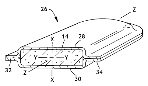
Referring to Fig. 7, a disposable product in the form of a sanitary napkin 26
is
shown having the absorbent member 14 enclosed by a liquid permeable cover 28
and a
liquid-impermeable baffle 30. The absorbent member 14 can be constructed to
swell,
when wetted, in only one direction, for example, in the x-direction, if
desired. Likewise,
the absorbent member 14 could be constructed to swell, when wetted, in two
directions,
or three directions, if that was useful. The cover 28 and the baffle 30
cooperate together
to completely enclose the absorbent member 14. This is different from Fig. 6
wherein the
layers 22 and 24 only partially enclosed the absorbent member 14. In Fig. 7,
the cover 28
and the baffle 30 are joined together to form longitudinal seals 32 and 34
adjacent to the
longitudinal sides of the sanitary napkin 26. The ends of the sanitary napkin
26 are also
sealed in a similar fashion by joining the cover 28 to the baffle 30.
Referring to Fig. 8, a disposable infant diaper 36 is shown having a front
section
38, a crotch section 40 and a back section 42. The crotch section 40 is
located between
the front section 38 and the back section 42. The diaper 36 is constructed of
a body
CA 02301395 2000-03-20
contacting, liquid permeable cover 44, a main absorbent 46 and a liquid-
impermeable
baffle 48. The cover 44 and the baffle 48 cooperate to at least partially, and
preferably,
completely enclose the main absorbent 46. The diaper 36 also has a front edge
50 and a
back edge 52. Extending laterally outward from the back edge 52 are ears 54
and 56.
Each ear 54 and 56 has an adhesive tab, 58 and 60, respectively. The ears 54
and 56
are designed to wrap around the torso of an infant and the adhesive tabs 58
and 60 are
designed to be attached to the front section 38 to hold the diaper 36 securely
in place. It
should be noted that alternative diaper designs could be utilized which have a
second pair
of ears extending laterally outward from the front section 38.
The diaper 36 further has a pair of leg cuffs 62 and 64 located on the outer
edges
of the crotch section 40. Inboard of the leg cuffs 62 and 64 are absorbent
gaskets 66 and
68. The absorbent gaskets 66 and 68 can be formed out of the absorbent member
14
disclosed above and can be constructed such that they will expand or swell in
one or
more directions when wetted by an aqueous fluid, such as urine. In addition,
the diaper
36 is depicted with a front, absorbent gasket 70 and a back absorbent gasket
72. The
front and back gaskets, 70 and 72 respectively, will prevent fluid leakage out
of the diaper
36 adjacent to the waist of the infant. Leakage at these locations can occur
when the
infant is sleeping or lying on his or her stomach, side or back.
It should be noted that the diaper 36 has a main absorbent member 46 and four
separate gaskets 66, 68, 70 and 72. However, a fewer number or a greater
number of
gaskets could be employed if desired. Likewise, additional absorbent layers
could be
utilized if desirable. The absorbent that is used to form the main absorbent
member 46
and each of the gaskets 66, 68, 70 and 72 can be constructed such that each
will
optimally perform the function for which it was designed. For example, the
main
absorbent member 46 can be constructed to expand in the x and y directions as
it takes
up body fluid while the gaskets 66, 68, 70 and 72 may be designed to swell in
the vertical
or z-direction as they absorb body fluid. The vertical swelling of the gaskets
66, 68, 70
and 72 will cause a snug seal to form with the body as they expand and this
will decrease
the likelihood of fluid leaking from the diaper 36 at these locations. Thus
one can see that
by constructing each absorbent within a particular article a certain way, that
the function of
the article can be greatly increased. In the case of the diaper 36, the
gaskets 66, 68, 70
and 72 will confine the body fluid in the crotch section 40 for a longer
period of time and
therefor give the main absorbent member 46 added time to absorb the fluid.
Additionally,
the gaskets 66, 68, 70 and 72 will expand and swell when wetted so as to form
dams
against the legs and torso of the infant to decrease the likelihood of leakage
at these
locations. The end result is a much better performing diaper 36 with the use
of less
absorbent material. Hence, the cost of the diaper may be reduced and the
infant may be
11
CA 02301395 2000-03-20
able to wear the diaper for a longer period of time. Furthermore, by
decreasing or
preventing the incidences of fluid leakage, there will be fewer times when the
outer
clothing wom by the infant will be soiled.
Referring to Figs. 9 and 10, a circular gasket 74 is shown positioned around
the
thigh of a person for preventing the passage of fluid. The gasket 74 could be
sized and
configured to be positioned about another limb or appendage of a human body or
of an
animal. The gasket 74 could be used for medical purposes, i.e. preventing
blood from
exiting a wound or for absorbent other body fluids, such as urine. The gasket
74 includes
an absorbent member 14 at least partially, and preferably completely, enclosed
by an
outer layer 76 and an inner layer 78. The layers 76 and 78 can be either
liquid permeable
or liquid-impermeable. The absorbent member 14 should be constructed such that
it can
expand or swell when wetted in a direction perpendicular to body part it
encircles. When
the gasket 74 is to prevent the passage of urine down the thigh, the absorbent
member 14
will increase in size as urine initially contacts it. As the absorbent swells,
a tighter and
snugger seal will be formed which will provide greater assurance that
additional urine
flowing down the thigh will not get past the gasket 74.
One or more of the gaskets 74 could be incorporated into a diaper, training
pants,
swim suit, etc. and be used to prevent the passage of urine down the thighs of
an infant or
child. Likewise, two such gaskets 74 could be incorporated into an adult brief
and prevent
the passage of urine down the thigh of the adult wearer.
Referring to Fig. 11, an alternative embodiment is depicted of an absorbent
article
80 having a multitude of fibers 82 and particles 84 enclosed in a liquid
permeable cover
86. The absorbent article 80 can be used for a variety of purposes and is
especially
useful in situations where liquid spills require quick action. For example, in
the case
where a liquid is spilled onto carpeting, the absorbent article 80 can be
rubbed onto the
spilled liquid and draw a significant quantity of the liquid out of the
absorbent yarns and
fibers of the carpeting. The contact and/or pressing of the absorbent article
80 against the
wet carpeting will draw the liquid out and retain it in the fibers 82 and in
the particles 84.
The liquid permeable cover 86 will allow for rapid intake of liquid while
retaining the fibers
82 and the particles 84 as a unit for easy disposal. The absorbent article 80
can also be
used for taking up a spill on a hard surface. The absorbent article 80 can be
constructed
to easily absorb up to about 15 grams of liquid per gram of absorbent.
Referring to Fig. 12, first and second pipes, 88 and 90 respectively, are
shown.
The pipes 88 and 90 can be concrete pipes having a large diameter of about 12
inches or
more. The first pipe 88 has an enlarged flange 92 formed on one end 94. The
enlarged
flange 92 is sized and designed to receive an end 96 of the second pipe 90.
When the
two pipes 88 and 90 are joined together, a small space 98 will be present. In
order to
12
CA 02301395 2000-03-20
close up the space 98 and form a tight seal between the two pipes 88 and 90,
an
absorbent gasket 100 can be positioned in the space 98. It has been found that
the
absorbent gasket 100 can be used where swelling with pressure build-up is
desired upon
contact with moisture. One particular use is in concrete pipes used to convey
sewage
and runoff water. When the two pipes 88 and 90 are laid in a trench formed in
the ground,
a larger gap is usually present on either the top or bottom surface of the two
pipes 88 and
90. In the past, Oakite~ has been used as the gasket material. Oakite~ has a
rope like
appearance and can be pounded into the space between the two pipes to provide
a tight
seal that would absorb some moisture to prevent leakage. Pounding the Oakite~
into
position was required because Oakite~ has very little wet expansion
properties.
The absorbent member 12 of this invention can be formed into the gasket 100
and
be placed between the two pipe88 and 90. The absorbent member 12 exhibits a
high
pressure for very small expansion conditions and is capable of expanding to a
greater
extent for larger gaps. Therefore, a loose fitting assembly of two pipes 88
and 90 can
easily be sealed by the absorbent gasket 100 when the absorbent member 12 is
contacted by a small amount of moisture or water.
It should also be noted that germicides can be added to the absorbent gasket
100
to preclude bacterial degradation when the gasket 100 is in contact with the
soil, for
example, when used under ground.
The absorbent member 14 can also be formed into other products. One such
product is a wiper, which can be used to wipe up spills. Today, most
commercially
available wipers made from tissue can quickly reach a liquid content that
results in leaving
a trace, trail or smear of water behind as it reaches its absorbent capacity.
A wiper
formed from the absorbent 14 of this invention will do away with the
likelihood of a trail
being left behind because of its ability to absorb additional liquid, as it is
wetted.
METHOD
Referring to Fig. 13, a method is depicted for making an absorbent member 12
from a multitude of the absorbent fibers 14. The method includes introducing
multiple
fibers 14 of chemi-thermo-mechanical softwood or bleached chemi-thermo-
mechanical
softwood into an air stream 102. The fibers 14 are entrained in the air stream
102 to form
an air-fiber mixture 104. Preferably, the air stream 102 is turbulent to
enhance the mixing
of the fibers 14.
It should be noted that the method described above refers to introducing the
fibers
14 into the air stream 102. However, particles 84, as described in reference
to Fig. 11,
could also be introduced in conjunction with the fibers 14, if desired.
13
CA 02301395 2000-03-20
The air-fiber mixture 104 is then directed to a porous media 106, such as a
wire
mesh screen. The porous media 106 has a first surface 108 that receives the
initial
contact by the air-fiber stream. The size and configuration of the porous
media 106 can
vary. For good results, a wire mesh value of "32 Standard Mesh" works well.
Alternatively, the porous media 106 can be a perforated plate having a
plurality of circular
apertures formed therethrough. A perforated plate having a plurality of
apertures of
about 0.038 inches in diameter with a 0.050 spacing therebetween work well.
The above
referenced plate will have an open area of about 45%. It should be noted that
the
dimensions of the apertures and the land areas could vary to suit one's
particular needs.
It should be further noted that the porous media 106 could be a tissue sheet,
a
nonwoven sheet, a porous wire, a screen or some other structure. The porous
media 106
could be planar in configuration or have an arcuate surface in one or more
directions.
When the porous media 106 has one or more arcuate surfaces, it allows forming
the
absorbent member 12 on drums as well as the forming of three-dimensional
shapes.
The air-fiber : nixture 104 should be uniformly distributed over the entire
first
surface 108 of the porous media 106 with a pressure differential across the
porous media
106 ranging from between about 3 to about 30 inches of water pressure. The air
portion
of the mixture 104 will pass through the porous media 106 while the fibers 14
will collect
on the first surface 108. As the air passes through the porous media 106, it
will leave the
fibers 14 behind. The air can then be recycled and reused, if desired. The
multitude of
fibers 14 are separated from the air and build up into a mat on the first
surface 108 of the
porous media 106. The porous media 106 acts like a filter separating the
fibers 14 from
the air stream 102. When the desired amount of fibers 14 have accumulated into
a
fibrous mat 110 having a predetermined thickness "t", the air stream 102 is
stopped or
halted. The air stream 102 can either be diverted away or be turned off as in
an
intermittent operation. The amount of fibers 14 accumulated to form the
fibrous mat 110
can vary from between about 20 to about 1,000 grams of fibers per square
meter.
The fibrous mat 110 is then removed from the first surface 108 of the porous
media 106. The fibrous mat 110 can be weighted to determine its basis weight
and
moisture content. Water 112 is then added to the fibrous mat 110 to obtain a
predetermined percent of moisture. This predetermined moisture value can be
any
desired value, for example, 5%, 10%, 15%, etc. depending on the later steps of
the
process. The water 112 can be added to the fibrous mat 110 in a number of
different
ways. Some of these ways include: misting the water 112 over the fibrous mat
110,
placing the fibrous mat 110 in a humidity chamber, or passing steam through
the fibrous
mat 110. The amount of water 112 added would determine the weight gain of the
fibrous
mat 110. Knowing the initial basis weight of the fibrous mat 110 and the basis
weight of
14
CA 02301395 2000-03-20
the fibrous mat 110 after the addition of a certain amount of water 112, one
can control
the percent moisture in the fibrous mat 110. The initial amount of water 112
present in the
fibers 14 making up the fibrous mat 110 will partially determine how much
water 112
should be added. The amount of water 112 added is established by knowing the
water
level of the fibers 14 before adding additional water 112. This can be
determined by
weighing a sample of the fibers 14 and then placing the fibers 14 in a balance
which is in
a heated environment (greater than about 100°C) to evaporate any
moisture until there is
no further weight loss. The weight difference divided by the original weight
is the portion
of water present. Therefore, the amount of water 112 needed to be added to the
fibrous
mat 110 can be established from the desired moisture percentage (for example,
10%),
and the measured initial moisture level.
Immediately following the addition of the water 112, the fibrous mat 110 is
subjected to a stressing condition andlor a compression step. The compression
of the
fibrous mat 110 can be accomplished by using a pair of flat platens to create
a one
dimensional change or by using configured platens to create a curved or
arcuately
stressed absorbent structure. The amount the fibrous mat 110 is compressed can
be
limited by the desire final thickness "t" of the absorbent member 12 or be
limited by the
desired maximum pressure that can be applied during the compression step.
Referring again to Fig. 13, the fibrous mat 110 is placed between two platens
114
and 116, at least one of which is movable. The platens 114 and 116 can be
heated, if
desired, to drive off excess moisture when present. As the first platen 114
moves toward
the second platen 116, the absorbent sheet 12 is compressed to a desired
thickness.
Besides using a pair of platens 114 and 116, the absorbent sheet 12 can be
compressed
by using a standard press or by conveying the absorbent sheet 12 through the
nip of a
pair of close or contacting pressure rolls.
It has been found that if a final nip compression of about 0.03 inches is
desired for
a fibrous mat 110 having an initial thickness of about 2 inches, that the
compression
should be done in a progressive series of steps. The steps will depend upon
the diameter
of the pressure rolls. One sequence would be to compress the fibrous mat 110
from an
initial thickness of about 2 inches (about 51 mm) down to about 0.25 inches
(about 6.4
mm). The next step is to compress the fibrous mat 110 down from about 0.25
inches
(about 6.4 mm) to about 0.03 inches (about 0.76 mm). This can be accomplished
using a
12 inch (305 mm) diameter steel roll interacting with a 4 inch (102 mm)
diameter steel roll.
This is the final step in the making of the absorbent member 12. Depending
upon the
moisture level, it is sometimes desirable to compress the fibrous mat 110 to
less than the
desired thickness and allow the absorbent member 12 to spring back to the
desired
thickness. For example, compress the fibrous mat 110 to a thickness of about
0.027
CA 02301395 2000-03-20
inches (about 0.69 mm) and allow it to spring back to a thickness of about
0.03 inches
(about 0.76 mm). _
Referring to Fig 14, a method is depicted for forming an absorbent member 12
in a
continuous fashion. This method includes introducing the fibers 14 into the
air stream 102
and forming an air-fiber mixture 104. This air-fiber mixture 104 is then
directed to an
endless belt 118. The endless belt 118 can be formed as a fine mesh wire and
has an
outer surface 120. The fibers 14 will collect on the outer surface 120 of the
belt 118 while
the air portion of the mixture 104 will be allowed to pass through the endless
belt and be
recovered, if desired. The level of pressure differential maintained across
the endless belt
118 will affect the density of the fibrous mat 110. At about 3 inches (about
76 mm) of
water pressure, the bulk density of the fibrous mat 110 could be 0.01
gramslcubic
centimeter (g/cc), while at about 30 inches (about 762 mm) of water pressure,
the density
could reach 0.1 glcc. The linear speed of the endless belt 118 will affect the
length of the
forming chamber needed to deposit adequate fiber 14 for forming the fibrous
mat 110.
The fibrous mat 110 formed on the endless belt 118 is then stripped off of the
outer surface 120 and is contacted with water 112. The water 112 can be
sprayed or
misted onto one or both sides of the fibrous mat 110. Preferably, a pre-
selected amount
of water 112 is sprayed over the entire width of the fibrous mat 110. This
provides for a
uniform distribution of hydrogen bonding to occur throughout the entire
fibrous mat 110.
The fibrous mat 110 is then routed through a nip 122 formed by finro
interacting pressure
rolls 124 and 126. The pressure rolls 124 and 126 can be heated to remove any
excess
moisture from the fibrous mat 110, if required. The compression nip 122 will
densify the
fiber network and allow hydrogen bonding to occur and form a compressed
fibrous mat
128. The compressed fibrous mat 128 can then be routed to a slitter and cutter
130
where the compressed fibrous mat 128 is cut and/or slit into desired sizes of
absorbent
member 12. Alternatively, the compressed fibrous mat 128 can be directed away
from
the slitter 130 and be rolled up onto hollow cores to form finished rolls, if
desired.
Referring now to Fig. 15, still another alternative method is depicted for
continuously forming an absorbent member 12. This method includes introducing
the
fibers 14 into the air stream 102 and forming an air-fiber mixture 104. This
air-fiber
mixture 104 is then directed onto a continuous first layer 132. The first
layer 132 is
unwound from a supply roll 134 and is conveyed by a drive mechanism 136 in a
desired
direction. The first layer 132 can be a porous tissue, a nonwoven fabric or
any other type
of natural or synthetic material. The drive mechanism 136 can be a drive
motor, an
endless belt, or some other type of means to pull or draw the first layer 132
along. As the
first layer 132 is unwound from the supply roll 134 it is conveyed pass a
location 138
where the air-fiber mixture 104 is deposited thereon.
16
CA 02301395 2005-08-05
The air-fiber mixture 104 can be deposited onto the first layer 132 at a
single
location 138 or it can be deposited onto the first layer 132 at multiple
locations (not
shown), to progressively build up the fibers 14. The thickness of the fibrous
mat 110 can
be varied by controlling the rate at which the air-fiber mixture 104 is
deposited onto the
first layer 132 and by controlling the speed of the first layer 132.
As taught above for Fig. 14, water 112 can be directed onto one or both sides
of
the fibrous mat 110. After the addition of the water 112, a second layer 140
can be
added to the fibrous mat 110. The second layer 140 can be unwound from a
supply roll
142 and can be similar or different from the first layer sheet 132. It should
be noted that
either one or both of the first and second layers, 132 and 140 respectively,
can become
part of the finished absorbent 12. For example, the first layer 132 can be a
liquid
permeable cover and the second layer 140 can be a liquid-impermeable baffle.
The
finished product would be a laminate of all three layers, cover 132, fibrous
mat 110 and
baffle 140.
When the first and/or second layers 132 and/or 140 respectively, are
constructed
from porous materials such as tissue, nonwovens or textiles, the fibrous mat
110 will have
a tendency to mechanically attach to the adjacent layers) when the composite
is routed
through the compression nip 122. Impervious layers, such as polymer films, can
be
attached to the fibrous mat 110 with an adhesive or by a corona treatment
before passing
the layers through the compression nip 122.
If it is desirable to increase fiber integrity of the fibrous mat 110, this
can be
accomplished by adding binder fibers. The binder fibers can be mixed with the
fibers 14
within the air stream 102 to form the mixture 104 which is then deposited onto
the first
layer 132. To increase integrity, long fibers having a length of greater than
about 4 mm
can be added to the air stream 102. The long fibers will provide mechanical
entanglement
and friction. Materials such as rayon, cotton, wool, etc. are good for
introducing long
fibers into the fibrous mat 110.
Furthermore, thermal-setting fibers can be mixed into the air stream 102 to
increase integrity. One type of thermal-setting fibers is known as "Pulpex"
and is available
from Hercules Inc. Hercules Inc. has a sales office in Wilmington, Delaware.
Thermal-
setting fibers can also be blown directly into the air stream, e.g., melt
blown fibers. These
thermal-setting fibers should be heated and cooled while the fibrous mat 110
has its
lowest density and before compression and hydrogen bonding. The use of a
heated
compression nip 122 can be adverse if it allows for thermal bonding between
the fibers in
the compressed high-density state. Therefore, a heated compression nip should
be
avoided when thermal-setting fibers are utilized.
*Trade-mark
17
CA 02301395 2000-03-20
Once the first and second layers, 132 and 140 respectively and the fibrous mat
110 pass through the nip rollers 124 and 126, a compressed fibrous mat 144 if
formed.
This compressed fibrous mat 144 can be directed to a slitter 130, as explained
above, to
form individual articles 146. Alternatively, the compressed fibrous mat 144
can be rolled
up into a larger roll, if desired.
Other chemical or particles can also be included within the fibrous mat 110 by
introducing them into the air stream 102 with the fibers 14. Such chemicals
and particles
could include superabsorbent particles or materials, deodorant particles,
encapsulated
dyes, encapsulated fragrances, catalyst particles, germicidal particles, etc.
It is also possible to stress the fibers 14 within the fibrous mat 110. By
using the
method described above, one can introduce the fibers 14 into the air stream
102 to form
entrained fibers in the turbulent air-fiber mixture 104. These fibers 14 are
then separated
out of the air-fiber mixture at the porous media106, the endless belt 118 or
at the carrier
sheet 132. When the fibers 14 are deposited using gravity onto a surface or by
using
electrostatic attraction of the fibers 14 onto a surface, a low-density (less
than about
0.lgram/cc) fibrous mat 110 is created. This low density fibrous mat 110 has
the fibers 14
arranged in a random orientation, for example, the long axis of the fibers 14
are likely to
be oriented in the x, y and z directions. When the fibers 14 contain a
significant
percentage of their original lignin content, for example about 80%, there will
be stresses
developed within the fibers 14 when they are bent, twisted, contorted,
crushed, or
otherwise changed from their relaxed shape. By using an external constraint
and force, a
large number of the fibers 14 can become contorted and hence stressed into a
dense
condition. This enables one to change the fibers 14 from a condition of low
density to a
condition of high density. Due to the random orientation of the fibers 14, a
large
percentage of the fibers 14 will have significant movement while being
compressed. For
example, the thickness of the fibrous mat 110 can be reduced from about 2
inches (about
51 mm) to a thickness of about 0.03 inches (about 0.76 mm). This movement
during
compression, along with the potential for many of the different fibers 14 to
impede or limit
any one fiber from moving relative to its full length, leads to a stressed
condition.
Stressing of the fibers 14 in two or three directions can be induced by
successive
partial compression of the fibers 14 in two or three different directions.
Compression in
three different directions can be achieved by forcing the low density fibers
14 through a
funnel shaped extruder where the progressively smaller diameters will compress
the fibers
14 in a radial direction while the pushing mechanism will compress the fibers
14 in an
axial direction. The addition of moisture to the fibers 14 will facilitate
hydrogen bonding in
the compressed condition. The stresses created in the fibers 14 and in the
fibrous mat
110 will show directionality when the stresses are relieved. This means that
when the
18
CA 02301395 2000-03-20
hydrogen bonds are broken, the fibers 14 will want to expand outward in a
direction
opposite to the direction in which they were compressed. An example of this
was carried
out in a test laboratory. Bleached chemi-thermo-mechanical softwood fibers 14
where
collected and formed into a fibrous mat 110 using the method depicted in Fig.
13. The
fibrous mat 110 had an initial density of 0.02 gram/cc and a thickness of
about 2 inches
(about 51 mm). The moisture level in the fibrous mat 110 was adjusted up to
about 10%
and the fibrous mat 110 was compressed in one direction (the z direction) to
reduce its
thickness down to about 0.03 inches (about 0.76 mm). Water was then applied to
the
fibrous mat 110 to cause expansion and swelling. The expansion was almost
entirely in
the z-direction, opposite to the force vector that was used to compress the
fibrous mat
110. The saturated fibrous mat 110 expanded from a thickness of about 0.03
inches
(about 0.76 mm) to a thickness of about 0.25 inches (about 0.64 mm) or an
increase of
about 700%. There was only minimal expansion in the x and y directions of
about 10% to
about 20%.
While the invention has been described in conjunction with a specific
embodiment,
it is to be understood that many alternatives, modifications and variations
will be apparent
to those skilled in the art in light of the aforegoing description.
Accordingly, this invention
is intended to embrace all such alternatives, modifications and variations
that fall within
the spirit and scope of the appended claims.
19