Language selection

Search

Patent 2301396 Summary

Third-party information liability

Some of the information on this Web page has been provided by external sources. The Government of Canada is not responsible for the accuracy, reliability or currency of the information supplied by external sources. Users wishing to rely upon this information should consult directly with the source of the information. Content provided by external sources is not subject to official languages, privacy and accessibility requirements.

Claims and Abstract availability

Any discrepancies in the text and image of the Claims and Abstract are due to differing posting times. Text of the Claims and Abstract are posted:

  • At the time the application is open to public inspection;
  • At the time of issue of the patent (grant).
(12) Patent Application: (11) CA 2301396
(54) English Title: WATER HEATER
(54) French Title: CHAUFFE-EAU
Status: Deemed Abandoned and Beyond the Period of Reinstatement - Pending Response to Notice of Disregarded Communication
Bibliographic Data
(51) International Patent Classification (IPC):
  • F23L 17/00 (2006.01)
  • F23L 17/04 (2006.01)
(72) Inventors :
  • CARLTON, CLIFFORD (United States of America)
  • VAGO, OTTO Z. (United States of America)
(73) Owners :
  • STATE INDUSTRIES, INC.
(71) Applicants :
  • STATE INDUSTRIES, INC. (United States of America)
(74) Agent: MACRAE & CO.
(74) Associate agent:
(45) Issued:
(22) Filed Date: 2000-03-20
(41) Open to Public Inspection: 2000-09-27
Availability of licence: N/A
Dedicated to the Public: N/A
(25) Language of filing: English

Patent Cooperation Treaty (PCT): No

(30) Application Priority Data:
Application No. Country/Territory Date
09/410,105 (United States of America) 1999-09-30
60/126,611 (United States of America) 1999-03-27

Abstracts

English Abstract


A water heater having a combustion air inlet and a flue gas outlet. A
manifold assembly is provided which includes a box section, a flue gas port, a
combustion air port and a combustion air inlet collar. The combustion air
inlet
collar communicates with the combustion air port through the interior of the
box section. A combination combustion air inlet and flue gas outlet assembly
is provided and includes a combustion air inlet tube and a flue gas outlet
tube
mounted concentrically inside the combustion air tube. The combustion air
tube is connected at one end to the box section of the manifold and is
connected at the other end with the atmosphere. The flue tube is connected at
one end to the flue gas inlet port on the manifold and communicates with the
atmosphere at the other end. An air blower is mounted on the water heater. A
combustion air tube is connected at one end to the combustion air port of the
manifold and is connected at its other end to an air assembly box mounted on
the top of the water heater. The air blower is operable to draw fresh
combustion air through the combustion air tube and then into the combustion
chamber of the water heater. A flue gas tube is connected at one end to the
flue gas port of the manifold and is connected at the other end to the blower,
which is operable to exhaust the flue gases from the combination combustion
air inlet and flue gas outlet assembly.


Claims

Note: Claims are shown in the official language in which they were submitted.

5
CLAIMS
We claim:
1. A water heater having a combustion chamber, a combustion air
inlet and a flue gas outlet located at the top of the water heater,
comprising:
(a) a manifold assembly (16) including a box section (30), a
flue gas port (32), a combustion air port (34) and a combustion air inlet
collar (36), said combustion air inlet collar (36) communicating with said
combustion air port (34) through the interior of said box section (30);
(b) a combination combustion air inlet and flue gas outlet
assembly (14) including a combustion air inlet tube member (18), a flue gas
outlet tube member (20) mounted concentrically inside said tube member (18),
said tube member (18) connected at one end to said box section (30) at said
combustion air inlet collar (36), said tube member (18) communicating with the
atmosphere and its other end, said tube member (20) connected at one end to
said flue gas inlet port (32) and communicating with the atmosphere at its
other end;
(c) a combustion air assembly box (44) mounted on the top
of the water heater;
(d) a combustion air tube (42) connected at one end to said
combustion air port (34) and connected at its other end to said combustion air
assembly box (44);
(e) a flue gas tube (38) communicating at one end with the
flue gas outlet of the water heater and connected at the other end to said
flue
gas port (32); and
(f) an air blower (40) operable to draw combustion air into
the water heater through said combustion air tube (42) and further operable to
draw flue gas out of the water heater through flue gas outlet tube (38).

6
2. A combination combustion air and flue gas exhaust system for a
water heater comprising:
(a) a manifold assembly (16) including a box section (30), a
flue gas port (32), a combustion air port (34) and a combustion air inlet
(36),
said combustion air inlet collar (36) communicating with said combustion air
port (34) through the interior of said box section (30);
(b) a combination combustion air inlet and flue gas outlet
assembly (14) including a combustion air inlet tube member (18), a flue gas
outlet tube member (20) mounted concentrically inside said tube member (18),
said tube member (18) connected at one end to said box section (30), said
tube member (18) communicating with the atmosphere and its other end, said
tube member (20) connected at one end to said flue gas port (32) and
communicating with. the atmosphere at its other end;
(c) a combustion air assembly box (44) mounted on the top
of the water heater;
(d) a combustion air tube (42) connected at one end to said
combustion air port (34) and connected at its other end to said air assembly
box (44);
(e) a flue gas tube (38) communicating at one end with the
flue gas outlet of the water heater and connected at the other end to said
flue
gas port (32); and
(f) an air blower operable to draw combustion air into the
water heater through said combustion air tube (42) and further operable to
draw flue gas out of the water heater through flue gas outlet tube (38).
3. A combination combustion air and flue gas exhaust system for a
water heater according to Claim 1 in which there is a combustion air assembly
box (44) through which combustion air is drawn into the combustion chamber
of the water heater by the operation of said air blower (40).

7
4. A water heater having a combustion chamber, a combustion air
inlet and a flue gas outlet located at the top of the water heater comprising:
(a) a manifold assembly (16) including a box section (30), a
flue gas port (32), a combustion air port (34) and a combustion air inlet
(36),
said combustion air inlet (36) communicating with said combustion air port
(34)
through the interior of said box section (30);
(b) a combination combustion air inlet and flue gas outlet
assembly (14) including a combustion air inlet tube member (18), a flue gas
outlet tube member (20) mounted concentrically inside said tube member (18),
said tube member (18) connected at one end to said box section (30), said
tube member (18) communicating with the atmosphere and its other end, said
tube member (20) connected at one end to said flue gas port (32) and
communicating with the atmosphere at its other end;
(c) a combustion air assembly box (44) mounted on the top
of the water heater;
(d) a combustion air tube (42) connected at one end to said
combustion air port (34) and connected at its other end to said air assembly
box (44);
(e) a flue gas tube (38) communicating at one end with the
flue gas outlet of the water heater and connected at the other end to said
flue
gas port (32); and
(f) an air blower operable to draw combustion air into the
water heater through said combustion air tube (42) and further operable to
draw flue gas out of the water heater through flue gas outlet tube (38).

8
5. A water heater having a combustion chamber, a combustion air
inlet and a flue gas outlet comprising:
(a) an air blower (40) mounted on a water heater;
(b) a combustion air tube (38) connected to said air
blower (40), said air blower (40) operable to draw fresh combustion air
through
said tube (42) and then into the combustion chamber of the water heater;
(c) a flue gas tube (38) connected to the flue gas outlet of
the water heater;
(d) a manifold assembly (16) communicating with said flue
gas tube (38) and said combustion air tube (42), said manifold assembly (16)
adapted to receive and conduct combustion air to said combustion air
tube (42), said manifold assembly (16) further adapted to receive flue gas
from
said flue gas tube (38); and
(e) a combination combustion air inlet and flue gas outlet
assembly (14) adapted to receive combustion air from the atmosphere and
conduct said combustion air to said manifold assembly (16), said combination
combustion air inlet and flue gas outlet assembly (14) further adapted to
receive flue gas from said manifold assembly (16) and conduct said flue gas to
the atmosphere.
6. A water heater according to Claim 3 in which said combination
combustion air inlet and flue gas outlet assembly (14) includes a combustion
air inlet tube member (18) and a flue gas outlet tube member (20) mounted
concentrically inside said tube member (18), said tube member (18) adapted
to conduct atmospheric air to said manifold assembly (16), said tube
member (20) adapted to conduct flue gas from said manifold assembly (16) to
the atmosphere.
7. A water heater according to Claim 5 in which said manifold
assembly (16) includes a box section (30) through which combustion air flows
from said combination combustion air inlet and flue gas outlet assembly (14)
to
said combustion air tube (42).

9
8. A method of heating water in a water heater, including a
water-tight tank (11), a combustion chamber (19), a gas burner (13) in the
combustion chamber, a flue gas outlet tube (17) connected to the combustion
chamber (19), a blower (40), a manifold assembly (16) having a combustion
air port (34) and a flue gas port (32), a combustion air tube (42) connected
to
the combustion air port (34) at one end and communicating with the
combustion chamber (19) at the other end, a flue gas tube (38) connected to
the flue gas port (32) at one end and communicating with the flue gas outlet
tube (17) of the water heater at the other end, comprising the steps of:
(a) energizing the blower (40) to draw combustion air into the
manifold assembly (16) and then from the manifold assembly (16) through the
combustion air tube (42) to the combustion chamber (19) of the water heater;
(b) mixing combustion air with gas produced by the gas
burner (13) and burning the mixture in the combustion chamber (19) to
produce heat;
(c) energizing the blower (40) to draw flue gases out of the
water heater and into the flue gas tube (38) which carries the flue gases to
the
manifold assembly (16).
9. The method of Claim 8 in which combustion air flows out the
manifold assembly (16) and into the combustion air tube (42) through a
combustion air port (34) on the manifold assembly (16).
10. The method of Claim 9 in which flue gases flowing from the flue
gas tube (38) to the manifold assembly (16) flow through the flue gas port
(32)
of the manifold assembly (16).

Description

Note: Descriptions are shown in the official language in which they were submitted.


' CA 02301396 2000-03-20
1
WATER HEATER
CROSS-REFERENCE TO RELATED APPLICATIONS
Not applicable.
STATEMENT REGARDING FEDERALLY SPONSORED
RESEARCH OR DEVELOPMENT
Not applicable.
REFERENCE TO MICROFICHE APPENDIX
Not applicable.
BACKGROUND OF THE INVENTION
This invention relates to a water heater and more specifically to a water
heater that is directly vented to the outside through the wall of the space in
which the water heater is located. An air blower forces combustion air through
a
manifold assembly and then into the combustion chamber of the water heater.
The air blower also draws products of combustion from the combustion chamber
through the manifold assembly and then out to the atmosphere.
A water heater of this general type is shown and described in U.S.
Patent No. 5,020,512. The present invention is believed to be a patentable
improvement over this prior water heater.
BRIEF SUMMARY OF THE INVENTION
A water heater having a combustion air inlet and a flue gas outlet
including an air blower mounted on the heater. The blower is operable to draw
fresh combustion air through the combustion air tube and into the combustion
chamber of the heater. A flue gas tube is connected to the flue gas outlet. A
manifold assembly is in communication with the combustion air tube and the

. CA 02301396 2000-03-20
2
flue gas tube. The manifold assembly is adapted to receive and conduct
combustion air to the combustion air tube. The manifold assembly is further
adapted to receive flue gas from the flue gas tube and direct the flue gas
through the assembly and then out to atmosphere. A combination combustion
air inlet and flue gas outlet assembly is adapted to receive combustion air
from
the atmosphere and conduct the combustion air to the manifold assembly. The
combination combustion air inlet and flue gas outlet assembly is further
adapted
to receive flue gas from the manifold and to conduct the flue gas to the
atmosphere.
BRIEF DESCRIPTION OF THE DRAWINGS
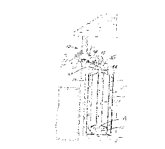
Fig. 1 is a partially schematic vertical side elevation view of a water
heater equipped with the combustion air and the products of combustion flue
gas piping system of the present invention;
Fig. 2 is a horizontal cross-sectional view of the combustion air and
products of combustion flue gas piping system;
Fig. 3 is a top view of the manifold assembly used in the system shown
in Fig. 1; and
Fig. 4 is a right-hand end elevation view of the manifold assembly shown
in Fig. 3.
DETAILED DESCRIPTION OF THE INVENTION
Referring to the drawings, Fig. 1 shows a gas-fired water heater 10
equipped with a combustion aiNflue gas piping system 12 as shown in Figs. 2, 3
and 4. As shown in Fig. 1, the internal construction of water heater 10
includes
a watertight tank 11, a gas-fired burner 13 mounted in a combustion
chamber 19, a passageway 15 to conduct combustion air to the burner and a
flue tube 17 for carrying the products of combustion out the top of the water
heater.

CA 02301396 2000-03-20
3
As shown in Fig. 2, piping system 12 includes a manifold assembly 16
and a combination combustion air inlet and flue gas outlet assembly 14.
Assembly 14 is comprised of an outer tube member 18 and an inner tube
member 20 mounted concentrically inside tube member 18. The inner tube 20
extends through the wall 22 of the space in which the heater is installed.
A perforated guard member 24 is mounted on the end of tube 20 outside
of wall 22. A fitting 25 is mounted on the end of tube 20. The fitting 25 has
side
openings 26 and an end cap 28.
Referring to Figs. 2, 3 and 4, manifold assembly 16 is mounted on the
right-hand end of assembly 14 adjacent the inside surface of wall 22.
Manifold assembly 16 is comprised of a manifold box section 30 and a
flue gas port 32 mounted in box 30 and extending through the box as shown in
Fig. 3. A combustion air port 34 is mounted on the face of box 30 and
' communicates with the interior of box 30 as shown in Fig. 3. Assembly 16 has
a
collar 36 on box 30 which, as shown in Fig. 2, fits inside the left end of
tube 18.
As shown in Figs. 1 and 2, a combustion air tube 42 is connected at one
end to combustion air port 34 of manifold assembly 16 and is connected at its
other end to an air assembly box 44 mounted on the top of heater 10. A flue
gas tube 38 is connected at one end to the flue gas port 32 of manifold
assembly 16 and is connected at its other end to a blower 40 mounted at one
end of air assembly box 43. An internal baffle 45 functions to direct
combustion
air from tube 42 into passageway 15. The baffle 45 further functions to direct
flue gas from flue tube 17 to tube 38.

CA 02301396 2000-03-20
4
OPERATION
With blower 40 (Fig. 1 ) energized, fresh combustion air will be drawn into
combination combustion air inlet and flue gas outlet assembly 14 through
perforated guard 24. Combustion air flows through tube 18 around the outside
of tube 20 as shown by the arrows in Fig. 2. The fresh combustion air exits
into
manifold assembly 16 as shown in Fig. 2. The combustion air flows through
manifold box section 30 to outlet port 34.
From port 34, the air flows through tube 42 to the air assembly box 44
(Fig. 1 ). Box 44 has an internal baffle 45 therein, which directs the flow of
combustion air into passageway 15 of the water heater. Blower 40 draws the
combustion air into the internal passageway 15 of heater 10, which directs the
flow to the burner 13 in the combustion chamber of the heater 10.
The products of combustion, f.e., flue gases, flow upwardly inside the
heater through tube 17 and exit the heater into tube 38 after passing through
air
assembly box 43 as shown by the arrows in Fig. 1. The flue gases flow through
tube 38 to inlet port 32 of manifold 16. The flue gases then flow through port
32
into tube 20 (Fig. 2), then through tube 20 and then out to the outside
atmosphere through openings 26 at the end of tube 20 (Fig. 2}.
While the invention herein has been shown and described in what is
presently conceived to be the most practical preferred embodiment, it will be
obvious to one of ordinary skill in the art that many modifications may be
made
thereof within the scope of the invention, which scope is not to be limited
except
by the appended claims.

Representative Drawing
A single figure which represents the drawing illustrating the invention.
Administrative Status

2024-08-01:As part of the Next Generation Patents (NGP) transition, the Canadian Patents Database (CPD) now contains a more detailed Event History, which replicates the Event Log of our new back-office solution.

Please note that "Inactive:" events refers to events no longer in use in our new back-office solution.

For a clearer understanding of the status of the application/patent presented on this page, the site Disclaimer , as well as the definitions for Patent , Event History , Maintenance Fee  and Payment History  should be consulted.

Event History

Description Date
Inactive: IPC expired 2022-01-01
Inactive: IPC from MCD 2006-03-12
Application Not Reinstated by Deadline 2004-03-22
Time Limit for Reversal Expired 2004-03-22
Deemed Abandoned - Failure to Respond to Maintenance Fee Notice 2003-03-20
Letter Sent 2001-04-06
Inactive: Single transfer 2001-03-08
Application Published (Open to Public Inspection) 2000-09-27
Inactive: Cover page published 2000-09-26
Amendment Received - Voluntary Amendment 2000-06-29
Inactive: IPC assigned 2000-05-10
Inactive: First IPC assigned 2000-05-10
Inactive: Courtesy letter - Evidence 2000-04-11
Inactive: Filing certificate - No RFE (English) 2000-04-06
Inactive: Applicant deleted 2000-04-05
Application Received - Regular National 2000-04-05

Abandonment History

Abandonment Date Reason Reinstatement Date
2003-03-20

Maintenance Fee

The last payment was received on 2000-08-16

Note : If the full payment has not been received on or before the date indicated, a further fee may be required which may be one of the following

  • the reinstatement fee;
  • the late payment fee; or
  • additional fee to reverse deemed expiry.

Patent fees are adjusted on the 1st of January every year. The amounts above are the current amounts if received by December 31 of the current year.
Please refer to the CIPO Patent Fees web page to see all current fee amounts.

Fee History

Fee Type Anniversary Year Due Date Paid Date
Application fee - standard 2000-03-20
MF (application, 2nd anniv.) - standard 02 2002-03-20 2000-08-16
Registration of a document 2001-03-08
Owners on Record

Note: Records showing the ownership history in alphabetical order.

Current Owners on Record
STATE INDUSTRIES, INC.
Past Owners on Record
CLIFFORD CARLTON
OTTO Z. VAGO
Past Owners that do not appear in the "Owners on Record" listing will appear in other documentation within the application.
Documents

To view selected files, please enter reCAPTCHA code :


To view images, click a link in the Document Description column. To download the documents, select one or more checkboxes in the first column and then click the "Download Selected in PDF format (Zip Archive)" or the "Download Selected as Single PDF" button.

List of published and non-published patent-specific documents on the CPD .

If you have any difficulty accessing content, you can call the Client Service Centre at 1-866-997-1936 or send them an e-mail at CIPO Client Service Centre.


Document
Description 
Date
(yyyy-mm-dd) 
Number of pages   Size of Image (KB) 
Representative drawing 2000-09-21 1 10
Description 2000-03-19 4 147
Abstract 2000-03-19 1 31
Drawings 2000-03-19 3 79
Claims 2000-03-19 5 200
Filing Certificate (English) 2000-04-05 1 163
Request for evidence or missing transfer 2001-03-20 1 108
Courtesy - Certificate of registration (related document(s)) 2001-04-05 1 113
Reminder of maintenance fee due 2001-11-20 1 112
Courtesy - Abandonment Letter (Maintenance Fee) 2003-04-16 1 176
Correspondence 2000-04-05 1 14