Note: Descriptions are shown in the official language in which they were submitted.
CA 02301490 2000-03-16
DISPOSABLE PROTECTIVE CLOSURE
BACKGROUND OF THE INVENTION
1. Field of the Invention
The present invention relates to closures and,
more particularly, pertains to disposable closures for
protecting exposed connecting portions of components
during handling, processing and shipping.
2. Description of the Prior Art
Disposable closures, such as plugs and caps, for
protecting openings, pipes, tubing, fittings, or
rodlike members during handling and shipping are well
known in the art.
For instance, United States Patent No. 3,574,312
issued on April 13, 1971 to Miller discloses a closure
comprising a hollow cylindrical body having a closed
end and an open end surrounded by an integral
peripheral flange. This type of closure may be used
either as a plug for insertion in bores or as a cap for
installation over the ends of cylindrical members. A
lip extends axially from the periphery of the flange to
facilitate removal of the closure from a bore when it
is desired to connect an associated fitting to the
bore. The flange and the lip are made of a flexible
CA 02301490 2000-03-16
- 2 -
material to ensure that the same will deform in the
presence of nearby objects.
When the closure is used as a plug, the peripheral
flange overlies the surface surrounding the bore in
which the plug is inserted to prevent the plug from
being accidentally pushed into the bore. However, in
some situations, for instance, where the outer diameter
of the peripheral flange is smaller than the inside
diameter of the fitting to be engaged with the tube in
which the plug is installed, nothing will
systematically prevent the fitting to be assembled to
the tube while the closure is still installed. This may
result in substantial damages.
Accordingly, it has been proposed to use closures
with a wide flange. Although, this solves the problem
to some extent, it has been found that such closures
could not be used in a great number of applications
where surrounding structures interfere with the
installation of this particular type of closure.
SUNIIKARY OF THE INVENTION
It is therefore an aim of the present invention to
provide a disposable closure which is adapted to
prevent a component from being erroneously connected to
CA 02301490 2000-03-16
- 3 -
another component while the disposable closure is still
installed on one of the components.
It is also an aim of the present invention to
provide a disposable closure which is relatively simple
and economical to manufacture.
Therefore, in accordance with the present
invention, there is provided a disposable closure for
protecting a port of a component, comprising a body
adapted to enclose an opening defined by the port, and
a projection extending away from the body relative to
the port offset from the opening, whereby the
projection will interfere with the connection of
another component with the port while the disposable
closure is still positioned to enclose the opening.
According to another general aspect of the present
invention, there is provided a disposable closure for
protecting an article, comprising a body configured to
be installed on the article to cover a portion thereof,
and a projection extending from the body to a position
spaced lengthwise from a trailing end of the body and
in a direction away from the article, the projection
having a portion spaced from a central axis of the
body, thereby providing visual indication of the
presence of the disposable closure on the article.
CA 02301490 2000-03-16
- 4 -
BRIEF DESCRIPTION OF THE DRAWINGS
Having thus generally described the nature of the
invention, reference will now be made to the
accompanying drawings, showing by way of illustration a
preferred embodiment thereof, and in which:
Fig. 1 is a perspective view of a disposable
protective closure having an interference member in
accordance with a first embodiment of the present
invention;
Fig. 2 is a cross-sectional view showing the
closure capping a tubular component;
Fig. 3 is a cross-sectional view of the closure of
Fig. 1 showing how the interference member prevents two
components from being assembled to one another while
one of the component is still plugged by the closure;
Fig. 4 is a perspective view of a disposable
protective closure in accordance with a second
embodiment of the present invention;
Fig. 5 is a cross-sectional view of the closure of
Fig. 4 showing how the interference member prevents two
components from being assembled to one another while
one of the component is still plugged by the closure;
Fig. 6 is a perspective view of a disposable
protective closure in accordance with a third
embodiment of the present invention; and
CA 02301490 2000-03-16
- 5 -
Fig. 7 is a cross-sectional view of the closure of
Fig. 6.
DESCRIPTION OF THE PREFERRED EMBODIMENTS
Now referring to the drawings, and in particular
to Fig. 1, a disposable protective closure embodying
the elements of the present invention and generally
designated by numeral 10 will be described.
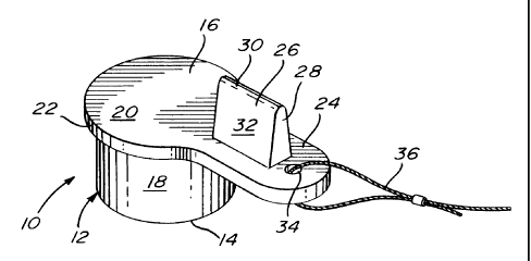
More particularly, the disposable protective
closure 10 comprises a hollow cylindrical body 12
having an open end 14 and a closed end 16. The body 12
is formed of a circular side wall 18 extending at right
angle from an end wall 20.
The end wall 20 projects radially outwardly of the
circular side wall 18 so as to form a rim 22 about the
closed end 16 of the hollow cylindrical body 12. The
rim 22 is formed with a radially extending tab 24 from
which a projection 26 extends in a generally normal
direction away from the open end 14 of the hollow
cylindrical body 12. The projection 26 has two opposed
end walls 28 and a top wall 30 merging with a pair of
opposed angled side walls 32. The angle side walls 32
provide a tapering profile to the projection 26 in a
direction away from the tab 24.
CA 02301490 2000-03-16
- 6 -
As seen in Fig. 1, a hole 34 may be defined in the
tab 24 for receiving an elongated fastener 36, such as
a lanyard, in order to secure the disposable protective
closure 10 to a structure surrounding the component on
which the closure 10 is installed. This may be useful
to provide clear indication that a closure is still
installed, particularly in applications where the
closure is otherwise not easily visible. Accordingly,
the elongated fastener 36 will serve as an additional
protection to prevent that two parts be assembled while
a protective closure is still installed on one of the
parts.
The disposable protective closure 10 is preferably
integrally molded from a plastic material, such as
polyethylene.
As seen in Figs. 2 and 3, the disposable
protective closure 10 may, for instance, be used as a
cap for installation over one end of a tubular
component C or as a plug for insertion at one end of a
tube T. However, it is understood that the disposable
protective closure 10 could be used to cover other
types of ports or threads. The term port is herein
intended to characterized the area of an opening in a
component face to be assembled to another component.
CA 02301490 2000-03-16
- 7 -
As seen in Fig. 2, the disposable protective
closure 10 may be positioned over one end of the
tubular component C to prevent moisture, debris and
other contaminants from entering the tubular component
C. The inner surface of the circular side wall 18 of
the hollow cylindrical body 12 is frictionally engaged
with the outer circumference of the tubular component C
to retain the disposable protective closure 10 thereon.
In this case, the circular side wall 18 of the hollow
cylindrical body 12 extends at least partly over the
outer connecting portion of the tubular component C and
thus contributes to prevent that another component be
engaged with the outer connecting portion of the
tubular component C. The tab 24 and the projection 26
offer additional protection to prevent assembly.
Indeed, as the tab 24 and the projection 26 are at
least partly positioned outwardly of the outer
circumference of the tubular component C, they will
interfere with the connection of another component with
the tubular component C. The thickness of the tab 24
and of the projection 26 is such as to ensure
sufficient structural rigidity to perform the intended
function.
The projection 26 could also be used to facilitate
removal of the closure 10 from the tubular component C.
CA 02301490 2000-03-16
- 8 -
Moreover, the tab 24 and the projection 26 contributes
to make the disposable protective closure 10 more
visible and thus further prevent potential incidents.
It is pointed out that in the event that the projection
26 and the tab 24 are only used to provide added visual
indication of the presence of the disposable protective
closure 10, the tab 24 and the projection 26 could be
made flexible.
As mentioned hereinbefore, the disposable
protective closure 10 may also be used as a plug to
prevent moisture, dirt and other contaminants from
entering a tube T during handling, processing and
shipping, as seen in Fig. 3. In such an application,
the hollow cylindrical body 12 is inserted in the tube
T with the outer surface of the circular side wall 18
frictionally engaging the inner circumference of the
tube T to retain the closure 10 in a functional
position thereof. The peripheral rim 22 formed by the
end wall 20 insures against the closure 10 being
accidentally pushed all the way into the tube T.
Since the tab 24 and the projection 26 extend
outwardly of the outer circumference of the tube and
thus outside of the inner circumference of a female
connector F, they will interfere with the connection of
the female connector F with the tube T, thereby
CA 02301490 2000-03-16
- 9 -
eliminating the risk that these two machined parts be
connected without having previously removed the
protective closure 10.
Fig. 4 illustrates another construction of a
disposable closure 110 in which the hollow body 112 has
a side wall 118 which defines tapering inner and outer
frustoconical surfaces 118a and 118b, thereby allowing
a same closure to be used in a wide range of opening
sizes. The disposable protective closure 110 also
differs from the protective closure 10 in that the rim
122 is integrally formed at the open end 114 of the
hollow body 12 rather than at the closed end 116
thereof. Furthermore, the rim 122 could be formed with
lateral flat portions 123 to provide added clearance.
This is particularly useful when it is desired to
install closures 110 in side by side openings which are
in close proximity to one another.
As seen in Fig. 5, the closure 110 is suited to be
used as a plug to cover an opening 0 defined in a
mounting surface M of a structural member S. Threaded
bores B are defined in the mounting surface M for
receiving bolts to assemble the structural member S to
a second structural member S' having a corresponding
mounting surface M'. In this situation, the
projection 126 will prevent the mating surfaces M and
CA 02301490 2000-03-16
- 10 -
M' from being placed in uniform contact, thereby
precluding the assembly of the structural members S and
S' while the closure is still positioned in the opening
0.
One advantage of the present invention resides in
the fact that the above described protective closures
and 110 can be used in a wide variety of
applications and still render ineffectible the
connection of components while the protective closure
10 is installed.
Figs. 6 and 7 illustrate a third embodiment of the
present invention wherein the disposable protective
closure 210 includes a hollow body 212 having a side
wall 218 which defines inner and outer frustoconical
surfaces 218a and 218b tapering from an open end 214 to
a closed end 216 of the hollow body 212. A rim 222
extends radially outwardly from the open end 214 of the
hollow body 212. A projection 226 extends axially from
the periphery of the rim 222 to interfere with the
connection of a component with another component in
which the closure is plugged, as per the way described
hereinbefore.
It is understood that the above described
protective closures 10, 110 and 210 may be used with
either threaded or non-threaded connectors.
CA 02301490 2000-03-16
- 11 -
According to a further embodiment of the present
invention, the projection could extend across the open
end of the closure. However, in this case, the closure
could only be used as a plug.