Note: Descriptions are shown in the official language in which they were submitted.
CA 02302043 2000-03-22
This invention relates to a method and device to hold a flexible bag in an
open manner in order
to facilitate its filling.
Bags such as refuse bags, shopping bags etc., used for collecting and holding
objects are
commonly made of flexible material such as plastics, fabric, paper or other
synthetics. They are
normally used for holding objects either for easy transportation, storage, or
disposal. The most
annoying problem in using a bag made of a flexible material is to maintain it
in an open manner for
filling. However, it is sometimes awkward for a user to open the bag with one
hand while filling it
with the other. For example, when using a flexible refuse bag outdoor for
collecting leaves in the fall,
the flexible bag would be fluttered by the wind which makes maintaining the
bag in the open condition
extremely difficult. Even indoor, it is inefficient and troublesome to
maintain the bag opened with one
hand and to fill it with the other only free hand.
Many devices have been developed to alleviate the above problem. One common
device is in
the form of a fixed bracket designed to match the size of the bag or slightly
larger. The flexible bag
may be mounted by stretching its lip portion to wrap tightly over the bracket.
The resilient tension
of the bag material would maintain the bag in the open manner. With this
device, the bracket must
have a relatively larger dimension than the lip portion of the bag creating
the resilient tension strong
enough to hold the bag mounted in an open manner. Often times, the lip portion
of the bag would
be tom when the user attempts to stretch it to wrap over the bracket.
Furthermore, in use, the weight
of the load in the bag would simply pull the bag off from the bracket. The
latter problem may be
mitigated by providing a support container having a comparable size as the
bag. It may be placed
within the container with its lip portion again stretched and wrapped tightly
around the upper opened
rim portion of the container so that the container would support the weight of
the load within the bag.
2
___;-r,.; ._
CA 02302043 2000-03-22
However, the bulkiness of the container makes it difficult to be carried
around. The container would
occupy storage space, and the lip portion of the bag is still subject to the
tearing problem. It is also
difficult to remove the bag from the container for its final destination, and
therefore, it limits the
benefits of using flexible bags.
There are devices for maintaining a flexible bag in the open condition with a
bracket having
fasteners provided thereon. The lip portion of the bag can be secured to the
bracket by the fasteners.
In U. S. Patent No.5,718,469 to F. G. Ockerman, it shows a portable mounting
device for a flexible
bag used for collecting and disposing animal excrement. The device consists of
a larger annular ring
and a smaller annular ring. The smaller ring is insertable into the larger
ring so that the lip portion of
the flexible bag may be sandwiched between the two rings thus mounted
together. Adjustable and
engageable fasteners are provided between the two annular rings for
maintaining the two rings tightly
mounted together. Such device is not desirable for mounting a flexible bag
intended for holding
objects having a relatively heavy weight since the weight of the objects would
pull the bag out of the
mounting.
U. S. Patent No.1,414, 575 to T. McCart shows a bag holder which consists of
an annular base
mounted on three supporting legs. The inner side wall of the annular base has
a stepped configuration
which is engageable with the similarly step configured outer side wall of a
funnel shaped chute. The
lip portion of a flexible bag can be sandwiched and grasped between the base
of the chute so as to
maintain it in the open condition. Such device would inherently damage the lip
portion of the bag by
the grasping action between the base and the chute. The weight ofthe load in
the bag would also tend
to pull the bag out from the mounting.
It is a principal object of the present invention to provide a mounting device
and method to
CA 02302043 2000-03-22
hold a flexible bag in an open condition for filling operation.
It is another object of the present invention to provide a mounting device in
which the
increasing weight of the load in the bag would enhance the tighter mounting
force of the bag to the
device.
It is another object of the present invention to provide a mounting device
which is simple in
construction and yet is easy to operate.
It is still another object of the present invention to provide a mounting
device which would
not cause any damage to the bag in its operation.
Other objects and advantages of the present invention will become apparent
from the
following detailed description of the preferred embodiments thereof in
connection with the
accompanying drawings in which
Figure 1 is a schematic side elevation view of two engaging hoops with the
inner hoop having
sloping side walls, illustrating the basic concept of the present invention.
Figure 2 is a schematic side elevation view of two engaging hoops with both
hoops having
mating sloping side walls, illustrating the basic concept of the present
invention.
Figure 3 is a schematic sectional side elevation view of the two engaging
hoops of Figure 2
with a flexible bag mounted thereto.
Figure 4 is a schematic side elevation view of the device of Figure 3 turned
to a 90 degree
position.
Figure 5 is a schematic side elevation view of two engaging hoops both having
curved sloping
side walls engaging with each other according to the present invention.
Figure 6 is a schematic side elevation view of the device of Figure 5 with a
flexible bag
4
CA 02302043 2000-03-22
mounted thereto and with a load located inside the bag.
Figure 7 is a perspective exploded side elevation view showing the basic
device of the present
invention in the form of two circular hoops having mating side walls.
Figure 8 is a perspective exploded side elevation view showing two hoops, each
hoop having
a flat back side wall and an arcuate front side wall and an additional
horizontal flange.
Figure 9 is a perspective exploded front elevation view showing a preferred
embodiment of
the device of the present invention.
Figure 10 is a perspective side elevation view of the Figure 9 with the inner
hoop inserted into
the outer binder hoop.
Figure 11 is a perspective front elevation view of the device shown in Figure
9 with a flexible
bag mounted thereto.
Figure 12 is a perspective exploded front elevation view of an embodiment of a
portable
construction of the device of the present invention in which the inner hoop
and the outer binder hoop
are substantially triangular in shape.
Figure 13 is a perspective exploded front elevation view of the device in
Figure 12 with a
flexible bag mounted thereto.
Figure 14 is a perspective front elevation view of the device in Figure 12
with the inner hoop
and the outer binder hoop fitted together.
Figure 15 is a perspective side elevation view of the device shown in Figure
14.
Figure 16 is a perspective top elevation view of the device shown in Figure
14.
Figure 17 is a perspective exploded front elevation view of another embodiment
ofthe device
of the present invention in which the outer binder is a counter top having
mating openings formed
5
CA 02302043 2000-03-22
therein.
Figure 18 is a perspective front elevation view of the device of Figure 17
with flexible bags
mounted thereto.
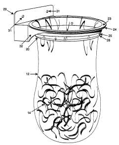
With reference to the drawings wherein like reference numerals designate
corresponding parts
in the several views, the basic principle of the present invention is
generally shown in Figures 1
through 6. The basic components of the present device comprises of an inner
hoop 10 having an
outer side wall sloping downwardly and inwardly and an outer binder 11 in the
form of a hoop having
an inner side wall with a shape and size adapted to fit over the outer side
wall of the inner hoop 10.
As shown in Figure 1, the inner side wall of the outer binder 11 is
substantially flat and vertical. The
inner side wall of the outer binder 11 may also have a similar sloping shape
as the outer side wall of
the inner hoop 10 as best shown in Figure 2 such that the inner hoop 10 and
the outer binder 11 may
mate intimately with each other. A flexible bag 12 may be mounted to the
device as best shown in
Figure 3 with the flexible bag 12 first inserted through the inner hoop 10 and
then with the bag's lip
portion 13 folded over to wrap over the outer side wall of the inner hoops 10.
The outer binder 11
is then fitted over the inner hoop 10 to sandwich the bag's lip portion 13
between the inner hoop 10
and the outer binder 11. The device would maintain the flexible bag 12 in the
open manner for filling
a load 14 into the bag. The weight of the load 14 will exert a pulling force
downwards on the inner
hoop 10 to cause it to engage tightly with the outer binder 11. As the bag is
being filled, the
increasing weight of the load will correspondingly exert an increasing force
to grasp the bag's lip
portion more tightly between the mating inner hoop 10 and the outer binder 11.
When the device is tilted to a substantially 90 degrees position as shown in
Figure 4 and
Figure 6, the weight ofthe load 14 in the bag 12 will pull and cause the inner
hoop 10 to engage more
6
CA 02302043 2000-03-22
tightly with the outer binder 11 as well as closing the opening of the bag as
long as the vector of the
downward force of the load falls within the combined center of gravity of the
mating inner hoop and
outer binder. Thus, the device with the bag mounted thereon is convenient for
carrying around in a
portable manner.
The inner hoop 10 and the outer binder 11 may have mating curved side walls as
shown in
Figures 5 and 6.
The flexible bag 12 with or without a load therein may be removed from the
device by simply
separating the inner hoop 10 and outer binder 11 apart from each other and ,
unfolding the lip portion
13 from the inner hoop 10 to remove the bag 12 therefrom.
It can be appreciated by those skilled in the art that the inner hoop 10 and
the outer binder
11 may have various different shapes as long as the outer side walls of the
inner hoop 10 and the inner
side walls of the outer binder 11 have a matching shape and size. For
illustration purposes, as shown
in Figure 7, the outer side wall of the inner hoop 10 and the inner side wall
of the outer binder 11
have a circular shape and similar complementary matching size so that they may
engage with each
other. Such circular shape device may also be mounted to a vertical supporting
wall surface with
mounting openings 15 and 16 provided in the side wall of the outer binder 11.
The associated large
openings 17 and 18 can be formed respectively in the side wall of the inner
hoop 10. The openings
17 and 18 will be in registry with the openings 15 and 16 when the inner hoop
10 and the outer binder
11 are fitted together so as to accommodate the head of the screws or nails
used for mounting the
device to the vertical supporting wall surface.
As shown in Figure 8, the inner hoop 10 may have a flat rear side wall 19 and
a curved front
side wall 20, while the outer binder 11 may have a similar hoop shape having a
corresponding flat rear
7
CA 02302043 2000-03-22
side wall 21 and a curved front side wall 22. The outer side wall of the inner
hoop 10 and the inner
side wall of the outer binder 11 have matching slope and size so that they may
mate with each other
intimately. Mounting openings 15 and 16 are provided in the flat rear side
wall 21 of the outer binder
11 and associated openings 17 and 18 are foamed in the flat rear side wall 19
of the inner hoop 10.
A flange 23 is formed at the top edge of the curved front side wall 20 of the
inner hoop 10 and a
corresponding flange 24 is also formed at the top edge of the curved front
side wall of the outer
binder 11.
A preferred embodiment of the device of the present invention particularly
suitable for
mounting it to a vertical supporting wall surface is best shown in Figures 9,
10 and 11. In this
embodiment, the inner hoop 10 is in the form of a circular hoop having a
flange 23 provided at its
entire top edge. The size of the inner hoop 10 may be equal to or smaller than
a conventional load
collection flexible bag. Four retainer openings 25 are formed close to the
lower edge 26 of the inner
hoop 10. The retainer opening 25 are spaced evenly over the side wall 20 of
the inner hoop 10. A slit
opening 26 extends from each retainer opening 25 to the lower edge 26. The
outer binder 11 is in the
form of a narrow hoop having a flange 24 formed at its top edge and a narrow
side wall 22. The top
flange 23 of the inner hoop 10 may be wider than the top flange 24 of the
outer binder 11 such that
when the inner hoop 10 is fitted within the outer binder 11, the top flange 23
extends outwards
beyond the peripheral edge of the top flange 24 of the outer binder 11. The
outer side wall 20 of the
inner hoop 10 is sloping downwardly and inwardly and the inner side wall 27 of
the outer binder has
a matching size to the outer side wall ofthe inner hoop 10. The inner side
wall 27 ofthe outer binder
11 may either have a matching complementary slope as the outer side wall 20 of
the inner hoop 10
or just simply be vertical. The inner diameter of the outer binder 11 may be
equal to or slightly larger
8
CA 02302043 2000-03-22
than the outer diameter of the inner hoop 10, such that the inner hoop 10 fits
easily into the outer
binder 11. An extension portion 28 is formed at the rear portion of the outer
binder 11. The
extension portion 28 has a vertical rear portion 29 and mounting openings 30
and 31 are formed
therein so that the device may be mounted to a vertical supporting wall in a
cantilever manner. A
reinforcing neck portion 32 is provided between the extension portion 28 and
the outer binder 11 so
as to support the weight exerted on the outer binder 11 by the load in the
flexible bag mounted to
device.
In Figure 11 the flexible bag 12 may be mounted to the device as best shown.
The flexible bag
12 is first inserted through the inner hoop 10 with its lip portion wrapping
over the upper flange 23
and the outer side wall 20 of the inner hoop 10. Sideway folded portions may
be formed in the
flexible bag's lip portion if the bag is larger than the diameter of the inner
hoop 10. These sideway
folded portions may be slipped or poked through the slits 26 into the
retaining openings 25 for
temporarily holding the flexible bag mounted to the inner hoop 10. The inner
hoop 10 with the
flexible bag 12 thus mounted may then be placed into the outer binder 11 until
the folded over lip
portion of the bag is sandwiched tightly between the mating inner hoop 10's
flange 23 and outer
binder 11's flange 24. The bag 12 may easily be removed by simply pushing the
inner hoop 10
upwards by its lower edge or by pulling its flange 23 upwards to disengage it
from the outer binder
11.
A portable embodiment of the device of the present invention is shown in
Figures 12 through
16. In this embodiment, the inner hoop 10 and the outer binder 11 have a
substantially similar
triangular shape. The front side walls are substantially V-shaped such that
the inner hoop 10 has two
substantially flat sides 31 and 32 and an extended flat side 33 extending
outwards beyond the rear
9
CA 02302043 2000-03-22
opening therein so that the hoop may rest on a horizontal supporting surface
thereby. Similarly, the
outer binder 11 has two substantially flat sides 34 and 35 and an extended
flat side 36. Mounting
openings 37, 38, 39 and 40 are formed in the extended flat side 36 of the
outer binder 11 such that,
if required, the device may be mounted to a vertical supporting surface. Four
similarly positioned
associated openings 41, 42, 43, and 44 are formed in the extended flat side 33
of the inner hoop 10.
The openings 41, 42, 43 and 44 are relatively larger in size than the openings
37, 38, 39 and 40
respectively and are intended to accommodate the head of the screws or nails
used for securing the
outer hoop 11 to the vertical supporting surface. A downwardly extending
dimple 45 is formed
adjacent to the rear edge of the rear opening at the underside of the extended
flat side 33 of the inner
hoop 10 as best shown in Figures 12 and 16. A mating depression 46 is formed
adjacent to the rear
edge on the upper surface ofthe outer binder 11 so that the dimple 45 will
engage with the depression
46 when the inner hoop 10 and the outer binder 11 are fitted together. This
provision is intended to
maintain the two parts held together particularly when the device is in
storage or during
transportation. The dimple and the depression may be formed in either the
inner hoop and the outer
binder 11 alternatively vice versa to provide the same purpose.
A plurality of transverse elongated openings 47 are formed in the flat side
34, and similarly
a plurality of transverse elongated openings 48 are formed in the flat side 35
of the outer binder 11.
Also, a plurality of short openings 49 are formed in the flat side 31 and a
plurality of similar short
openings 50 are formed in the flat side 32 of the inner hoop 10. The short
openings 49 will be in
registry with the elongated openings 47 and the short openings 50 will be in
registry with the
elongat~l openings 48 when the inner hoop 10 and the outer binder 11 are
engaged with each other
so that they may be separated from engagement by inserting fingers into the
elongated openings 47
__ ___-
i ~,~ _ _ _--._.___.
CA 02302043 2000-03-22
and 48 and short openings 49 and 50 to slide the inner hoop and the outer
binder apart from each
other.
The size of the inner hoop 10 is preferably smaller than or equal to the size
of a conventional
flexible bag so that it is not necessary to over stretch the lip portion of
the bag for mounting it onto
the inner hoop 10 initially.
The side walls of the inner hoop 10 and outer binder 11 preferably are sloping
about 5 to 15
degrees relative to their central axes from the front opening to the rear
opening such that the device
will lean backwards about 5 to 15 degrees from the vertical axis so as to
provide a more stable
position when it is resting on a horizontal surface by the extended side.
In operation, as shown in Figure 13, a flexible bag 12 may be mounted to the
device by first
inserting it through the inner hoop 10 and wrapping its lip portion 13 over
the outer side wall of the
inner hoop 10; any excess lip portion of the bag 12 larger than the opening of
the inner hoop 10 may
be folded sideways to wrap over the hoop. The inner hoop 10 with the lip
portion 13 of the bag 12
thus wrapped and folded thereon may then be inserted into the outer binder 11
with the flexible bag
12 now extending through the two engaging parts. The lip portion 13 of the bag
12 is sandwiched
between the mating inner hoop 10 and the outer binder 11. Thus, the flexible
bag 12 is maintained
in the open manner for the filling operation. The device with the flexible bag
12 mounted thereon may
be carried with a handle 51 at the top of the outer binder 11, or it may be
set on the ground with the
extended side 36 of the outer binder 11. In this position, objects on the
ground may be simply swept
into the bag. A convenience opening 52 is formed in the handle 51, as the
handle has a closed front
wall, for hanging the device in storage. To remove the bag 12 from the device,
the user simply inserts
fingers through the elongated openings 47 and 48 of the outer binder and the
short openings 49 and
11
CA 02302043 2000-03-22
50 to disengage slidably the inner hoop 10 from the outer binder 11.
Waste collection bags may be mounted to a counter top with the embodiment as
shown in
Figures 17 and 18. In this embodiment, binding openings 53 and 54 are formed
in the counter 55 to
serve as outer binders. Two inner hoops 56 and 57 having downwardly and
inwardly sloping outer
side walls 58 and 59 respectively are provided. Two waste collection bags 60
and 61 may then be
mounted to the counter 55 in the similar manner as described above. The two
bags construction is
shown as an example, a single bag may be mounted in the similar manner by
providing only a single
binding opening in the counter top.
It can be appreciated by those skilled in the art that the present device is
simple to fabricate
particularly for the portable embodiment in which the inner hoop and the outer
binder are similar in
general construction. With the unique construction, a plurality of the device
may be conveniently
stacked together for transportation or storage.
While the preferred embodiments of the invention have been described above. It
will be
recognized and understood that various modifications may be made therein and
the appended claims
are intended to cover all such modifications which may fall within the spirit
and scope of the
invention.
12