Note: Descriptions are shown in the official language in which they were submitted.
CA 02302098 2000-03-24
SWASH PLATE TYPE COMPRESSOR IN WHICH LUBRICATION
IS FAVORABLY KEPT AS REGARDS A PISTON JOINT
Backgiround of the Invention:
The present invention relates to a swash plate type compressor and,
more particularly, to a piston joint of the same.
A conventional swash plate type compressor comprises a rotary shaft, a
swash plate rotatable together with the rotary shaft, a reciprocatable piston,
and
a piston joint for coupling the piston with the swash plate. The piston joint
usually includes a socket connected integral with the piston and a pair of
shoes
(for example, see Japanese Unexamined Patent Publications Nos. S61-135990,
S49-65509, and S56-138474). The socket has concave surfaces opposite to
1o each other. The swash plate is inserted between the concave surface of the
socket. The shoes are interposed between the swash plate and the concave
surfaces, respectively. Each of the shoes has a flat surface slidable relative
to
the swash plate and a convex surtace opposite to the flat surface and slidable
relative to the concave surface.
During the compressor is operative, the shoes wobble inside the socket
of the piston in accordance with the rotation of the swash plate. Therefore,
it is
desired to keep sufficient lubrication between the convex surfaces of the
shoes
and the concave surfaces of the socket. Such lubrication can be attained by a
mist of lubricating oil contained in refrigerant gas within the compressor
being
2o introduced between the convex surfaces of the shoes and the concave
surfaces
of the socket.
CA 02302098 2000-03-24
2
Conventionally, the convex surfaces of the shoes and the concave
surfaces of the socket are designed to be substantially same to each other in
radius of curvature (for example, see Japanese Unexamined Patent Publication
No. H10-220354). With this structure, there is substantially no clearance
between the convex surfaces of the shoes and the concave surfaces of the
socket. Therefore, a mist of lubricating oil is hardly introduced between the
convex surfaces of the shoes and the concave surfaces of the socket. This
may spoil the keep of the sufficient lubrication between the convex surfaces
of
the shoes and the concave surfaces of the socket so as to wear the sliding
to surfaces to widen the clearance.
~ummarVr of the Invention:
It is therefore an object of the present invention to provide a swash
plate type compressor in which lubricating oil can be sufficiently supplied
between convex surfaces of shoes and concave surfaces of a socket.
Other objects of the present invention will become clear as the
description proceeds.
According to the present invention, there is provided a swash plate type
compressor which comprises a rotary shaft, a swash plate rotatable together
with the rotary shaft, a piston, and a shoe interposed between the swash plate
2o and the piston for converting the rotation of the swash plate into a
reciprocating
motion of the piston, the shoe having a spherically convex surface, the piston
having a concave surface for receiving the spherically convex surface, the
concave surface having a first and a second spherical surface which are
adjacent to and offset from each other to make a slight step extending along
the
concave surface.
Brief Description of the Drawings:
Fig. 1 is a longitudinal sectional view of a swash plate type compressor
according to an embodiment of the present invention;
CA 02302098 2000-03-24
3
Fig. 2 is a front view showing a concave surface of a socket included in
the swash plate type compressor of Fig. 1;
Fig. 3 is a sectional view for explaining the relation between the socket
and a shoe included in the swash plate type compressor of Fig. 1; and
Fig. 4 is an enlarged sectional view showing the actual relation between
the socket and the shoe.
Referring to Fig. 1, description will be made as regards a swash plate
type compressor according to an embodiment of the present invention.
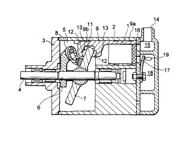
The swash plate type compressor is for use in a vehicle air conditioner
and comprises a cylinder block 2 and a front housing 3 connected to a front
portion of the cylinder block 2. The cylinder block 2 has at its rear end
portion
a plurality of cylinder bores 1 disposed at equal circumferential intervals. A
rotary shaft 4 is rotatably supported by the cylinder block 2 and the front
~5 housing 3.
The cylinder block 2 and the front housing 3 cooperate to define a crank
chamber 5 in which a rotor 6 and a swash plate 7 are disposed. The rotor 6 is
fixed to the rotary shaft 4 so as to rotate together with the rotary shaft 4.
The
swash plate 7 is connected to the rotor 6 by a hinge mechanism 8 so as to have
20 variable angle relative to the rotary shaft 4. It is to be noted that the
swash
plate 7 also rotates together with the rotary shaft 4.
The swash plate type compressor further comprises a piston 9 having a
piston body 9a at its one end side. The piston body 9a is inserted in each
cylinder bore 1 in such a manner that the piston body 9a can axially slide
25 relative to the cylinder bore 1. The piston 9 has a socket 9b at the other
end
side thereof. The socket 9b has a plate receiving groove 11 formed in the
socket 9b in which a portion of .the peripheral portion of the swash plate 7
is
arranged. The plate receiving groove 11 is defined between a pair of opposite
CA 02302098 2000-03-24
4
surface or walls and has concave surfaces 12 which are formed on the opposite
surfaces or walls, respectively.
The swash plate type compressor further comprises a pair of shoes 13
which are interposed between the swash plate 7 and the concave surfaces 12,
respectively. During the rotation of the swash plate 7, the shoes 13 slide
along
the swash plate 7 and are pressed in the axial direction, thereby converting
the
rotation of the swash plate 7 into a linear reciprocating motion of the piston
9
within the cylinder bore 1. The stroke of the piston 9 is variable in
accordance
with the angle of the swash plate 7 relative to the rotary shaft 4. Herein, a
1o combination of the socket 9b and the shoes 13 will be called a piston
joint.
When the piston 9 reciprocates within the cylinder bore 1, refrigerant
gas flows into a inlet chamber 15 through an inlet port 14, is sucked into the
cylinder bore 1 through an inlet opening 16, and then is discharged to a
discharge chamber 18 through a discharge opening 19 and flows out through a
discharge port 19. In the manner known in the art, a cooling circuit is
connected between the inlet port 14 and the outlet port 19. The cooling
circuit
is for providing air conditioning action in the vehicle. It should be
understood
that the refrigerant gas usually contains refrigerating machine oil, i.e.
lubricating
oil.
2o Referring to Figs. 2 and 3 in addition, the description will now be made
as regards the piston joint.
In the piston joint, each of the shoes 13 has a flat surtace 13a slidable
relative to the swash plate 7 and a spherically convex surtace 13b formed on
the opposite side thereof. The spherically convex surface 13b is formed along
a general spherical surface having a zeroth radius of curvature R0.
On the other hand, each of the concave surfaces 12 of the socket 9b is
a surface consisting of a first and a second spherical surfaces 12a and 12b
arranged adjacent to each other. The first spherical surface 12a has a first
CA 02302098 2000-03-24
radius of curvature R1. The second spherical surface 12b has a second radius
of curvature R2. In other words, a half of the concave surface 12 has the
first
radius of curvature R1 while the other half has the second radius of curvature
R2. The second radius of curvature R2 is set to be substantially equal to the
5 zeroth radius of curvature R0. The first radius of curvature R1 is set to be
slightly larger than the second radius of curvature R2 only by several microns
or
less. As a result of difference of the first and the second radii of curvature
R1
and R2, the first and the second spherical surfaces 12a and 12b are offset
from
each other to make a slight step extending along each of the concave surfaces
l0 12.
It is preferable that relations among the zeroth, the first, and the second
radii of curvature R0, R1, and R2 are determined as follows:
R2 - RO ~ 25 a m
and ( R2 - R1 I S 30 a m.
When the shoe 13 is placed in the concave surface 12, the slight step
causes a small gap or space 21 between the spherically convex surface 13b of
the shoe 13 and the concave surface 12 of the socket 9b as shown in Fig. 3 in
an exaggerated way. Since an external force is exerted, actually the concave
surface 12 may be in contact with the spherical surface 13b substantially
throughout the concave surface 12 as shown in Fig 4. Even in this event, a
very small gap or space extending along the boundary between the spherical
surfaces 12a and 12b still exists.
In operation, refrigerating machine oil stuck to the swash plate 7 is
supplied to the space 21 with a mist of refrigerant by means of centrifugal
force
developed by the rotation of the swash plate 7 so that an oil film is formed
on
the spherically convex surtace 13b of the shoe 13. This keeps high lubrication
between the spherically convex surface 13b of the shoe 13 and the concave
surtace 12 of the socket 19b, thereby preventing wear of the sliding surfaces.
CA 02302098 2000-03-24
6
While the present invention has thus far been described in connection
with a single embodiment thereof, it will readily be possible for those
skilled in
the art to put this invention into practice in various other manners. For
example, the difference between the first and the second radii of curvature
may
exceed several microns. The concave surface of the socket may consist of a
combination of three difference radii of curvature or more. The angle of the
swash plate relative to the rotary shaft may be fixed. The center of the first
radius of curvature may be coincide with or may not be coincide with the
center
of the second radius of curvature. The second radius of the curvature may be
1o set to be larger or smaller than the zeroth radius of curvature.