Note: Descriptions are shown in the official language in which they were submitted.
CA 02302114 2000-03-27
1
TITLE OF THE INVENTION
CONSTRUCTION BEAM
FIELD OF THE INVENTION
The present invention relates to construction beams.
More specifically, the present invention relates to a construction beam
mostly made of extruded elements.
BACKGROUND OF THE INVENTION
Metallic construction beams are well known in the art.
They are usually made of webbing material mounted between a top rail
and a bottom rail. In many cases, the top and bottom rails are made of
two L-shaped channels mounted on either sides of the webbing material
through soldering.
A drawback of the above described metallic beam is the
fact that the webbing material is soldered between the L-shaped
"channels" thereby weakening both the webbing material and the
channels. Indeed, the unequal heat distribution during soldering may
cause the material to loose part of its original strength. Furthermore, the
assembly of the above described metallic beam is labor intensive, which
leads to an increased overall cost of the conventional construction beam.
CA 02302114 2000-03-27
2
OBJECTS OF THE INVENTION
An object of the present invention is therefore to provide
an improved construction beam.
Another object of the invention is to provide a
construction beam free of the above-noted drawbacks of the prior art.
Other objects, advantages and features of the present
invention will become more apparent upon reading of the following non
restrictive description of preferred embodiments thereof, given by way of
example only with reference to the accompanying drawings.
BRIEF DESCRIPTION OF THE DRAWINGS
In the appended drawings:
Figure 1 is a perspective view of a construction beam
according to a first embodiment of the present invention;
Figure 2 is a sectional view taken along line 2-2 of
Figure 1;
Figure 3 is a sectional view taken along line 3-3 of
Figure 1;
CA 02302114 2000-03-27
3
Figure 4 is a side elevational view of a spacer as used
in the construction beam of Figure 1;
Figure 5 is a sectional side elevational view of one of
the rails used in the construction beam of Figure 1 as taken from line 5-5
of Figure 3;
Figure 6 is a sectional side elevational view of one of
the rails used in the construction beam of Figure 1 as taken from line 6-6
of Figure 3;
Figures 7 to 15 illustrate one possible sequence of
assembly of the construction beam of Figure 1;
Figure 16 is a perspective view of a construction beam
according to a second embodiment of the present invention;
Figure 17 is a perspective view of a construction beam
according to a third embodiment of the present invention;
Figure 18 is a sectional view taken along line 18-18 of
Figure 17;
Figure 19 is a sectional end view illustrating a
construction beam according to a fourth embodiment of the present
invention;
CA 02302114 2000-03-27
4
Figure 20 is a sectional side elevational view of a top
rail, according to a fifth embodiment of the present invention, having a
double-angle flange;
Figure 21 is a sectional side elevational view of a top
rail, according to a sixth embodiment of the present invention, having an
angled flange;
Figure 22 is a sectional end view of two construction
beams according to a seventh embodiment of the present invention; the
two construction beams being generally parallel and provided with
bridging members;
Figure 23 is a sectional end view of two construction
beams according to an eight embodiment of the present invention; the
two construction beams being generally parallel and provided with
bridging members;
Figure 24 is a perspective view of a construction beam
according to a ninth embodiment of the present invention;
Figure 25 is a sectional view taken along line 25-25 of
Figure 24;
Figure 26 is a side elevational view of a rail used in the
construction beam of Figure 24;
CA 02302114 2000-03-27
Figure 27 is a side elevational view of a spacer used in
the construction beam of Figure 24;
Figure 28 is an exploded perspective view of the
5 construction beam of Figure 24;
Figure 29 is a side elevational view of a first
embodiment of an adjustable height spacer;
Figure 30 is a side elevational view of a second
embodiment of an adjustable height spacer; and
Figure 31 is a side elevational view of a third
embodiment of an adjustable height spacer.
DESCRIPTION OF THE PREFERRED EMBODIMENT
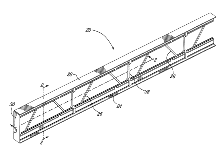
Turning now to Figures 1 to 6 of the appended
drawings, a construction beam 20 according to a first embodiment of the
present invention will be described.
The construction beam 20 includes a top rail 22, a
bottom rail 24, a plurality of brace elements 26, a plurality of spacer
elements 28 and two end plates 30 (only one shown). As will be further
described hereinbelow, the braces 26 and spacers 28 are mounted
between the top and bottom rails 22, 24.
CA 02302114 2000-03-27
6
As can be better seen from Figures 5 and 6, the top rail
22 includes a flange 31, and a guiding portion 33 including two
longitudinal guides 32, 34 defining, with a portion of the flange 30, a
generally U-shaped channel 36. The guides 32 and 34 are respectively
provided with external and longitudinal spacer retaining projections 38
and 40. Smaller internal braces retaining projections 42 and 44 are
respectively provided on the internal surface of the longitudinal guides 32
and 34. Finally, projections 46 and 48 are respectively provided on either
sides of the longitudinal guides 32 and 34. The specific purpose of the
projections 38 to 48 will be described in greater details hereinbelow. As
illustrated in Figures 3 and 6, the projections 38, 40, 42 and 44 are not
continuous along the entire length of the top rail 22 but are strategically
removed from portions of the rail 22 as will be discussed hereinafter.
More specifically, the projections 38 and 40 are provided with relatively
narrow notches 41 while the projections 42 and 44 are provided with
relatively wide notches 45.
As will easily be understood by one skilled in the art, the
bottom rail 24 is identical to the top rail 22 and will therefore not be
described in greater details hereinbelow.
The top and bottom rails are advantageously made by
an extrusion process of an extrudable material such as, for example,
aluminium or plastic material.
Turning now to Figure 4 of the appended drawings, the
spacer 28 will be described in greater details. The spacer 28 is
symmetrical about a first symmetry axis 47. Thereby, for concision
CA 02302114 2000-03-27
7
purposes, only the top portion of the spacer 28 will be described
hereinbelow.
The spacer 28 has a three-arm forked end 48
symmetrical about a second symmetry axis 50. The generally flat ends
of the lateral arms 52 and 54 are provided with respective rectangular
channels 56 and 58 configured and sized to receive the projections 46
and 48 of the top rail 22. Channels 60 and 62, provided between the
lateral arms 52, 54 and the central arm 64, are so configured that they
can respectively receive the guides 32, 34 along with the associated
spacer retaining. projections 38 and 40. Indeed, the apertures 60 and 62
have a profile that is complementary with the guides 32 and 34. It is to
be noted that the channels 60 and 62 respectively include abutting
portions 61 and 63 that are configured to respectively contact shoulders
39 and 41 of the spacer retaining projections 38 and 40 to thereby
prevent transversal separation (see arrow 78 of Figure 2) of the spacer
28 from the rail 12 or 14.
The central arm 64 is so configured and sized that it
may be inserted in the channel 36 of the rail 22. It is to be noted that the
central arm 64 is shorter than the lateral arms 52 and 54 to allow the
longitudinal portion of the braces 26 to be inserted therein as will be
described hereinbelow. As will be understood by one skilled in the art
upon reading the ongoing description, the spacer 28 could be so
designed that only one end thereof has a shorter arm 64 and the other
has a central having the same length as the lateral arms 52 and 54.
CA 02302114 2000-03-27
8
The spacers 28 are advantageously made by an
extrusion process of an extrudable material. More specifically, an
extrusion having the profile of the spacers 28, as shown in Figure 4, may
be made and subsequently cut into spacers 28 having the desired width.
Returning now briefly to Figure 1 of the appended
drawings, the braces 26 are configured and sized to be inserted in the
channel 36. More specifically, as can be better seen from Figure 3, each
brace 26 includes first and second angled portions 66 and 68, a
connecting portion 70 and two end portions 72 and 74 defining
supplemental connecting portions as will be described hereinbelow. The
connecting portion 70 and the two end portions 72 and 74 are parallel
and are configured and sized to fit in the channel 36 of the rails 22 and
24. The portions 70, 72 and 74 are provided with longitudinal channels
76 (Figures 2 and 7) that are positioned and sized to receive the internal
braces retaining projections 42 and 44 of the top and bottom rails 22 and
24. It is to be noted that the channels 76 are not aligned on either sides
of the braces 26 to prevent the undue weakening of the brace 26.
As will easily be understood by one skilled in the art, the
braces 26 could be divided in two by cutting the connecting portion 70 in
two (not shown), thereby yielding a shorter brace.
As can be seen from Figure 3 of the appended
drawings, the shorter central arm 64 of the spacer 28 is such that it abuts
against the end portions 72 and 74 of adjacent braces 26, thereby
increasing the strength of the interconnection between the braces 26 and
the rail 24.
CA 02302114 2000-03-27
9
Figure 2, which is a sectional view taken along line 2-2
of Figure 1, illustrates the interconnection of the various elements to
define the construction beam 20. As can be seen from this figure, the
projections 38 and 40 are positioned in the apertures 60 and 62 to
thereby prevent unwanted movements of the spacer 28 in the transversal
direction of arrow 78. Similarly, the interconnection of the projections 42
and 44 of the rail 22 and the channels 76 of the braces 26 prevented
unwanted movements of the brace 26 in the transversal direction of arrow
78. Finally, the respective interconnection of the projections 46 and 48
of the rails in the rectangular channels 56 and 58 of the spacer 28
prevent disengagement of the spacer from the rails should lateral
pressure be applied to the assembled construction beam 20 or to a
portion thereof.
Turning now to Figures 7 to 15, a possible sequence of
steps in the assembly of the construction beam 20 as illustrated in
Figures 1 to 6 will be described. It is to be noted that the possible
sequence of steps described hereinbelow is schematic and that the
various possible machines or jigs required to assemble the construction
beam 20 are not illustrated in Figures 7 to 15 for clarity purpose and
since the scope of such machines or jigs is beyond the scope of the
present invention. (???)
In Figure 7, the required braces 26 are positioned end
to end so that the end portion 74 of each brace 26 abuts the end portion
72 of an adjacent brace 26. A spacer 28 is provided in the proximity of
each junction of adjacent braces 26.
CA 02302114 2000-03-27
Figure 8 illustrates the assembly of the spacers 28 to
the braces 26. As can be seen from this figure, the shorter arm 64 of the
spacer 28 abuts the junction between adjacent braces 26.
5 In Figure 9, a top rail 22 is positioned in the proximity of
the braces 26 and spacers 28. It is to be noted that the top rail 22 is so
positioned that each spacer 28 faces a corresponding notch 41 having a
width sufficient to easily allow the insertion of the spacer 28 therethrough.
Similarly, each connecting portion 70 faces a notch 45 (see Figure 3),
10 provided in the channel 36, having a width sufficient to easily allow the
insertion of the connecting portion 70 of the braces therethrough.
Figure 10 illustrates the connection of the braces 26 and
spacers 28 to the top rail 22. It is to be noted that this connection is not
yet very secure since the braces 28 still face the notches 41 and the
connecting portions 70 still face the notches 45 (not shown).
Figure 11 illustrates the result of the sliding of the top
rail 22 in the direction of arrow 80. As will easily be understood by one
skilled in the art, this sliding movement of the top rail 22 thereby locks the
braces 26 and the spacers 28 in the top rail 22.
Turning now to Figure 12, the bottom rail 24 is
positioned in the proximity of the braces 26 and spacers 28. It is to be
noted that the bottom rail 24 is so positioned that each spacer 28 faces
a corresponding notch 41 having a width sufficient to easily allow the
insertion of the spacer 28 therethrough. Similarly, each connecting
portion 70 faces a notch 45 (see Figure 3), provided in the channel 36,
CA 02302114 2000-03-27
11
having a width sufficient to easily allow the insertion of the connecting
portion 70 of the braces therethrough.
Figure 13 illustrates the connection of the braces 26 and
spacers 28 to the bottom rail 22. It is to be noted that this connection is
not yet very secure since the braces 28 still face the notches 41 of the
bottom rail 24 and the connecting portions 70 still face the notches 45
(not shown) of the bottom rail 24.
In Figure 14, the bottom rail 24 has been slid in the
direction of arrow 82 to thereby lock the braces 26 and the spacers 28 in
the bottom rail 24.
Finally, the last step in the assembly of the construction
beam 20 is the assembly of the end plates 30 to the top and bottom rails
22 and 24. As can be seen from Figure 15, the end plate 30 has a
generally T-shape cross-sectional profile defined by a flange 84 and a
generally perpendicular connecting portion 86. It is to be noted that the
connecting portion 86 is so configured and sized as to be inserted in the
channel 36 of both the top and bottom rails 22 and 24. The connecting
portion 86 is therefore provided with notches to prevent interference with
the internal projections 42 and 44 of the rails 22 and 24. The end plate
is advantageously secured to the top and bottom rails via fasteners,
for example, self-threading screws (not shown), going through both
25 longitudinal guides 32 and 34 of the rail and through the connecting
portion 86 of the end plate 30. Of course, other fastening means could
be used.
CA 02302114 2000-03-27
12
Optionally, fasteners, such as for example, self-
threading screws (not shown) could be used to secure the various
elements 22, 24, 26 and 28 of the construction beam 20 together.
However, it has been found that this is not usually required to do so when
the various elements are adequately dimensionned as to allow their
assembly without allowing too much play between them.
Turning now to Figure 16 of the appended drawings, a
construction beam 200 according to a second embodiment of the present
invention will be briefly described. Since the construction beam 200 is
very similar to the construction beam 20, only the differences
therebetween will be described.
The main difference between the construction beam 200
and the construction beam 20 is the fact that the construction beam 200
has three rails: a top rail 202, an intermediate rail 204 and a bottom rail
206. Rails 202 and 206 are identical to the top rail 22 illustrates in details
in Figure 5.
The intermediate rail 204 has two guiding portion similar
to the guiding portion 33 of rail 20 (see Figure 5) provided on either sides
of its flange 208, thereby allowing braces 26 and spacers 28 to be
connected to both sides thereof.
A third embodiment of a construction beam 300
according to the present invention is illustrated in Figures 17 and 18 and
will be described hereinbelow.
CA 02302114 2000-03-27
13
Again, the construction beam 300 is similar to the
construction beam 20 illustrated in Figures 1-15. Therefore, only the
difference between these two beams will be briefly described
hereinbelow.
The construction beam 300 includes about twice as
much spacers 28 as does the construction beam 20. Indeed,
supplemental spacers 28a, identical to spacers 28, are provided between
the spacers 28. To accommodate these spacers 28a, supplemental
notches 41 a have been provided to the top and bottom rails 302 and 304.
The rails 302 and 304 are slightly different from the rail
22 since they lack the internal projections 42 and 44. The braces 306 do
not include channels corresponding to these projections. Indeed, it is
believed that the extra strength provided by the supplemental spacers
28a make the projections 42 and 44 extraneous. Of course, these
projections and the complementary channels could also be provided.
Figure 19, in a sectional side elevational view, illustrates
a construction beam 400 according to a fourth embodiment of the present
invention. The beam 400 has a top rail 402, a bottom rail 404 and a
plurality of braces 26 and spacers 28 identical to the ones forming the
construction beam 20 of Figures 1-15. The identical top and bottom rails
402 and 404 are significantly wider than the corresponding top and
bottom rails 22 and 24 of the construction beam 20 since they are
provided with three (3) sets of identical guiding portions 406, 408 and
410 similar to the guiding portion 33 of the construction beam 20. As will
CA 02302114 2000-03-27
14
easily be understood by one skilled in the art, the construction beam 400
is significantly stronger than the construction beam 20.
Figures 20 and 21 illustrate different possible cross-
sectional profile of the top rail.
More specifically, Figure 20 illustrates a top rail 500
having a double-angle flange 502. The top rail 500 may be used, for
example, at the roof's ridge.
The top rail 600, shown in Figure 21, has an angled top
flange 602. Uses for such a top rail 600 includes, for example,
construction beams used along rooftops.
Turning now to Figure 22 of the appended drawings, two
construction beams 700 and 702 according to a seventh embodiment of
the present invention that are generally parallel and interconnected by a
bridging assembly defined by two bridging members 704, 706. As can be
seen from this figure, the spacers 708 are provided with L-shaped
projections 710 integrally formed therewith. These projections 710 are
configured and sized to receive the ends 712 of the bridging members
704 and 706. Advantageously, fasteners, for example, self-threading
screws (not shown), could be used to secure the ends 712 of the bridging
members 704 and 706 to the beams 700 and 702.
Figure 23 is very similar to Figure 22 since it illustrates
two construction beams 800 and 802, according to an eight embodiment
CA 02302114 2000-03-27
of the present invention, that are generally parallel to one another and
interconnected by bridging members 804 and 806.
To secure the bridging members 804 and 806 to the
5 beams 800 and 804, the spacers 808 are provided with angled
projections 810 having transversal channels 812, 814 on opposite sides
thereof. These channels are staggered to prevent undue weakening of
the projection 810.
10 The ends of the bridging members 804 and 806 are
provided with transversal channels 816 configured and sized to receive
the projections 810. More specifically, the channels 816 include teeth
818 and 820 that are respectively complementary with the channels 812
and 814 of the projections 810. Again, fasteners, for example, self-
15 threading screws (not shown), could advantageously be used to secure
the bridging members 804 and 806 to the projections 810 of the beams
800 and 802.
Turning now to Figures 24 to 28 of the appended
drawings, a construction beam 900 according to a ninth embodiment of
the present invention. The construction beam 900 includes a top rail 902,
a bottom rail 904, a plurality of braces 906, a plurality of spacers 908 and
two end plates 910 (only one shown).
Again, only the top rail 902 will be described
hereinbelowwith reference to Figure 26 since the top and bottom rail are
identical.
CA 02302114 2000-03-27
16
The top rail 902 includes a flange 912 and two
longitudinal guides 914, 916 integrally formed with the flange 912 via, for
example, an extrusion process. Longitudinal guide 914 includes a first
projection 918 which is generally perpendicular to the flange 912 and a
second projection 920 which is inwardly angled. Of course, the
longitudinal guide 916 also includes identical projections 922, 924. The
longitudinal guides 914 and 916 define, with a portion of the flange 912,
a longitudinal spacer receiving space having generally triangular cross-
section in which the braces and spacers may be inserted.
Turning now to Figure 27 of the appended drawings, a
spacer 908 will be described. The spacer 908 includes opposite ends
portions 926, 928 having a generally triangular cross-section configured
and sized to be connected to the top and bottom rails 902 and 904. For
concision purposes and since the opposite ends of the spacer are
identical, only end portion 926 will be described in greater details
hereinbelow.
The end portion 926 includes a central rectangular
channel 930 sized to receive the braces 906, two generally parallel
channels 932 and 934 sized to respectively receive the projections 918
and 922 of the rail 902 and two angled channels 936 and 938 sized to
respectively receive the angled projections 920 and 924 of the rail 902.
These projections and channels, along with the general profile of the end
portions and of the longitudinal guides, prevent lateral separation (see
arrow 940 in Figure 25) of the spacer 908 with respect to the rails 902
and 904.
CA 02302114 2000-03-27
17
As can be clearly seen from Figure 27, the end portion
926 is not solid but includes a plurality of apertures 940 are provided
therein.
As will be readily understood by one skilled in the art,
since the rails 902 and 904 are not provided with notches allowing the
braces 906 and spacers 908 to be inserted therein, the braces and
spacers are inserted through one end or the rails and slid towards the
other end thereof.
The channels 930 of the spacers 908 receive the
longitudinal portions 942 and 944 of the braces 906. The stabilization
of the braces and spacers is helped by the projections 920 and 924 that
provided a relatively large resting surfaces between which the braces and
spacers are maintained. Of course, as will easily be understood by one
skilled in the art, supplemental spacers 908 could be used between the
spacers shown in the figures.
Optionally, fasteners, such as self-threading screws,
could be used to secure the spacers 908 to the longitudinal guides 914
and 916.
It is to be noted that while the embodiments of the
construction beam of the present invention illustrated in Figures 1 to 28
and described hereinabove display a fixed height, it would be possible to
provide extendible spacers to limit the number of different pieces
necessary to assembly construction beams according to the present
CA 02302114 2000-03-27
18
invention having different height. Of course, the same exercise could be
done for the braces.
Figures 29 to 31 illustrate, in side elevational views,
three embodiments of such variable length spacers.
In Figure 29, a three-piece spacer 1000 is illustrated.
The spacer 1000 includes two identical forks 1002 and 1004
interconnected by a heigth adjusting element 1006. Since the
interconnections between the forks 1002, 1004 and the heigth adjusting
element 1006 is identical to the interconnection between the bridging
elements 804, 806 and the spacers 808 of Figure 23, these
interconnections will not be further discussed herein.
Another three-piece spacer 1008 is illustrated in Figure
30. Two different length forks 1010 and 1012 are interconnected by a H-
shaped connector 1014. Fasteners (not shown), for example, self-
threading screws, are advantageously used to interconnect the various
elements of the spacer 1008. It is to be noted that fork 1010 includes
projections 1016 intended to receive a portion of the connector 1014.
Finally, Figure 31 illustrates a five-piece spacer 1018
comprising two identical forks 1020, 1022, each provided with projections
1024, two identical H-shaped connectors 1026, 1028 and a square heigth
adjusting rod 1030. Again, fasteners (not shown), for example, self-
threading screws, are used to interconnect the various elements of the
spacer 1018.
CA 02302114 2000-03-27
19
As will easily be understood by one skilled in the art,
even though the rails and spacers have been illustrated in the appended
drawings as being made of a solid extrusion, these elements could be
made via an extrusion process that generates extrusions having empty
spaces therein such as, for example, honeycomb patterns. This would
yield lighter rails and spacers which would, of course, yield lighter
construction beams.
Although the present invention has been described
hereinabove by way of preferred embodiments thereof, it can be
modified, without departing from the spirit and nature of the subject
invention as defined in the appended claims.