Note: Descriptions are shown in the official language in which they were submitted.
. ,
CA 02302130 2000-03-27
CONTAINER FOR FLOOR BOX WITH INTEGRAL
TEMPORARY COVER
Background of the Invention'
This invention relates generally to packages for electrical
wiring devices, and more particularly to a package for a floor box that
includes an integral, separable temporary cover for protecting the floor
box between the time it is installed and the time an electrical outlet or
the like is installed in the box and the box closed.
Floor boxes far mounting wiring devices flush with the surface
of floors in buildings are well known. Typically, such floor boxes
include a body portion that is mounted in the sub-floor prior to the
installation of a floor covering such as wood, carpeting, tile or the like.
After the body of the floor box is mounted in the sub-floor, the floor is
completed by applying the covering. A wiring device is installed in
the body of the floor box, and the floor box is closed by installing a
trim piece that extends through the floor covering into appropriately
sized recesses in the floor box body to form a seal.
It is a problem with installations of the type described that there
is a substantial period of time between the installation of the body of
the floor box in a sub-floor and the closing of the box by installing a
wiring device and subsequently installing the trim piece in the floor
box, during which debris may collect in the body of the floor box from
subsequent construction activities in the room in which the floor box is
mounted.
The debris must either be removed, because, if allowed to
remain in the floor box, it could create a hazard or at least present an
unsightly appearance.
One solution to the foregoing problem is to find something with
which to cover the floor box and temporarily secure it in place. A
scrap of construction material secured with tape or the like could be
. used, but this is an undesirable solution since an appropriate piece of
material may not always be available, and even if available; might be
dislodged during subsequent construction.
It is an object of this invention to provide a solution for the
foregoing problem.
-1-
CA 02302130 2000-03-27
It is a specific object of the invention to provide a container for
the floor box that includes an integral temporary cover that can be
placed over the body of the floor box after it is installed to
substantially close the floor box until a wiring device is mounted in the
floor box and a trim piece is installed to cover the floor box. It is
another object of this invention to provide a temporary cover that can
be easily separated from the container for the floor box with simple
tools readily available, such as a knife.
It is still another object of the invention to provide such a
temporary cover that does not significantly increase the cost of the
container for the floor box.
Briefly stated, and in accordance with a presently preferred
embodiment of the invention, a package for an electrical floor box of
the type adapted to be mounted in a sub-floor for receiving a wiring
device to allow connection to an electrical circuit includes a cardboard
container having a size sufficient to permit the floor box to be
contained therein, a reclosable flap for allowing the cardboard
container to.be opened for receiving the floor box and closed to
enclose the floor box in the cardboard container, and indicia on the
surface of the cardboard container defining the perimeter of a portion
of the box adapted, when separated from the remainder of the container
and folded, to form a temporary cover for the floor box for at least
partially closing the container.
In accordance with another aspect of the invention, instructions
are printed on the cardboard container for separating a portion of the
container defined by the indicia from the remainder of the container.
In accordance with still another aspect of the invention, the
indicia are on the reclosable flap of the cardboard container.
In accordance with still another aspect of the invention, the
portion of the container separable from the remainder of the container
is defined at least in part by a line of weakness generally coincident
with the indicia, so that the temporary cover can be removed from the
cardboard container without tools.
In accordance with a further aspect of the invention, the line of
weakness is a line of perforations and the temporary cover is separated
-2-
CA 02302130 2000-03-27
from the remainder of the cardboard container by tearing along the line
of perforations.
In accordance with a still further aspect of the invention, the
portion of the container defined by the indicia comprises a central
rectangular area having a pair of rectangular lateral wings, the central
rectangular area sized to substantially cover at least a portion of the
floor box and the lateral wings adapted to engage openings in the floor
box for securing the temporary cover in place.
In accordance with another embodiment of the invention, a
method for temporarily covering an opening in a floor box includes the
steps of providing a floor box in a cardboard container having indicia
on the container defining the perimeter of a portion of the container
adapted, when separated from the container and folded, to form a
temporary cover for the floor box for at least partially closing the floor
box, and separating the portion of the container defined by the indicia
from the remainder of the container, and covering the floor box with
the portion of the container defined by the indicia.
In accordance with another aspect of the method of the
invention, instructions are provided on the cardboard container
describing a method of separating the portion of the container defined
by the indicia from the remainder of the container.
In accordance with another aspect of the method of this
invention, covering the floor box with the temporary cover comprises
the step of folding a portion of the container defined by the indicia to
form a flap for insertion into a corresponding portion of the floor box.
Brief Descrirztion of the Drawing
The novel aspects of the invention are set forth with
particularity in the appended claims. The invention itself, together
with further objects and advantages thereof may be more readily
comprehended by reference to the following detailed description of a
presently preferred embodiment of the invention taken in conjunction
with the accompanying drawing in which:
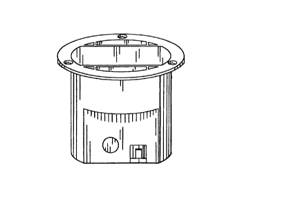
Figure 1 is a perspective view of the body portion of the floor
box of the type to which this invention pertains;
-3-
CA 02302130 2000-03-27
Figure 2 is a perspective view of a container for the floor box
of Figure 1;
Figure 3 is a plan view of a portion of the container of Figure 2
showing indicia defining a temporary cover;
Figure 4 is a plan view of the temporary cover removed from
the remainder of the container for the floor box;
Figure 5 is a perspective view of the temporary cover with flap
portions thereof folded relative to the body of the temporary cover;
Figure 6 is a perspective view of the temporary cover installed
in the floor box.
Detailed Descytion of the eferred Embodiment ~f rhP TnvPntinn
Referring now to Figure 1, a floor box of the type to which this
invention pertains is illustrated in a perspective view. The floor box 10
includes a hollow body portion 12 adapted to receive an electrical
wiring device such as a receptacle connected to an electrical circuit or
the like, and a flange 14 for supporting the floor box on the surface of a
sub-floor which can be a wooden sub-floor in a residential structure, or
a concrete sub-floor in a commercial structure. The floor box includes
openings 16 through which an electrical cable may be passed for
connecting a wiring device to an electrical circuit.
During construction, it is customary to install the floor box in
the sub-floor prior to installation of the final floor covering, which may
be carpeting, wood flooring, tile, or any other material customary in
the trade. During the time between installation of the floor box and
completion of the construction, debris tends to fall into the floor box
and accumulate. Preferably the debris is removed from the floor box
before a wiring device is installed therein, and this requires an extra
operation and possibly extra equipment such as a vacuum cleaner or
the like. Although the floor box could be covered with a piece of scrap
material to prevent or reduce the amount of debris falling into the box,
a suitable piece of material is not always available and therefore this is
an undesirable approach.
In accordance with the invention, a container 20 for the floor
box such as the one shown in Figure 2 is provided. The container,
preferably a cardboard container of otherwise conventional
-4-
CA 02302130 2000-03-27
construction incudes a reclosable flap that can be opened by the
manufacturer to insert the floor box into the container and then
resealed for shipping, storage or the like. The container may have
other flaps of conventional design, and the conventional aspects of the
container form no part of this invention except in combination with the
other elements hereof, as will be described below.
The container 20 according to the invention includes indicia 24
inscribed on a surface 26 of the container 20 preferably on the flap 22
defining the perimeter of a removable portion 28 of the container that
can be formed into a temporary cover for the floor box.
More specifically, and refernng now to Figure 3, the indicia 24
defines a central generally rectangular portion 32 sized to substantially
cover the open portion of the floor box. The generally rectangular
center portion comprises substantially the entire width of the closable
top flap of the cardboard container of Figure 2, this being a result of
the relative size of the container and the floor box. First and second
flaps or wings 34, 36 are attached to opposite edges of the rectangular
portion of the disposable cover, as defined by the indicia. The width of
the wings taken together with the width of the rectangular portion is
substantially equal the width of the reclosable flap 22 from which the
removable cover is separated. The width of the generally rectangular
center portion is less than the width of the flap by a substantial margin,
but is sufficiently wide to cover the open portion of the floor box, as
can be seen in Figure 5.
In accordance with one embodiment of the invention, the
indicia are merely printed on the surface of the container as part of the
labeling process. A removable cover defined by the printed indicia can
be separated from the remainder of the container by cutting with a
knife or scissors or the like, or by carefully tearing along the periphery
of the removable cover, guided by the indicia.
. In accordance with another embodiment of the invention,
separating the removable cover from the remainder of the container
may be simplified by providing one or more lines of weakness
generally coincident with at least portions of the indicia. Lines of
weakness may be formed by spaced perforations, scoring or any other
-5-
CA 02302130 2000-03-27
technique well known to those skilled in the art. As so formed, the
temporary cover may be removed from the remainder of the container
more readily, without tools, for example by tearing along the line of
weakness. Obviously a knife, scissors or the like may still be used if a
line of weakness is provided, but such tools are not required.
Once the temporary cover 40 has been separated from the
remainder of the container by cutting or tearing along the lines
indicated by the indicia, the temporary cover is formed into a U-shape
by bending the wings 34, 36 relative to the rectangular central body
portion 32, as shown in Figure 5 As so formed, the temporary cover
may then be attached to the floor box by inserting the wings into
openings 42, 44 in the floor box adjacent the central cavity thereof, in
which the wiring devices are mounted. The natural resilience of a
cardboard or other material from which the container is formed, such
as plastic, recycled plastic or paper material or the like causes the
wings to expand from their folded positions into engagement with the
' sides of the cavities in the floor box in which they are inserted, thereby
holding the temporary cover in place without the need for tape,
adhesives or the like.
Where the floor box, as is commonplace, has a generally round
configuration, the wings may be formed to substantially exclude debris
from the cavities in which they are placed, specifically by arranging
the indicia to form round ends on the wings, which are sized to engage
the rounded inner periphery of the cavities into which the wings are
inserted.
In accordance with another aspect of the invention, additional
indicia may be optionally provided for describing a fold line on the
wings. If the wings are folded along this line, they form a V-shaped
member which may be inserted into the opening in the floor box
adjacent the main cavity to even more securely anchor the temporary
cover to the floor box and provide the additional advantage of
improved protection against debris re-entering the openings adjacent
the main cavity.
While the invention has been described in connection with
certain presently preferred embodiments thereof, those skilled in the art
-6-
CA 02302130 2000-03-27
will recognize that many modifications and changes may be made
therein without departing from the true spirit and scope of the
invention, which accordingly is intended to be defined solely by the
appended claims.