Note: Descriptions are shown in the official language in which they were submitted.
CA 02302231 2000-03-O1
WO 99/11902 PCT/GB98/02582
- 1 -
Method and Apparatus for Aligning Tubulars
This invention relates to a method and apparatus
for aligning tubulars.
During the construction, repair and maintenance of
oil and gas wells it is necessary to connect a plurality
of tubulars. Conventionally this is achieved via screwed
connections.
In order to screw the tubulars together it is usual
to hold a lower tubular having an upwardly facing socket
in slips in the rig floor. The downwardly extending pin
of the next tubular is then aligned with the socket. The
tubular is then lowered into position and the upper
tubular rotated to the desired torque to make the con
nection.
It is important that the pin should be correctly
aligned with the socket prior to lowering the upper
tubular since, if this is not the case, the tubular
being lowered can damage the thread of the socket which
can prevent satisfactory connection.
One known apparatus for aligning tubulars comprises
a positioning head which is mounted on a telescopic arm
which can be hydraulically extended and retracted and
pivoted in a horizontal plane to position the tubular.
This apparatus is actuated remotely by a skilled
operator who has a control panel-with a joystick. This
apparatus is very satisfactory. However, time is criti
cal in the oil and gas industry and even a few seconds
saved in each connecting operation can amount to a very
significant overall cost saving.
With this in mind the present invention provides a
method for aligning tubulars, which method comprises the
steps of:-
a) securing a lower tubular in slips;
b) aligning an upper tubular with said lower tubu-
CA 02302231 2000-03-O1
..
WO 99/11902
- 2 -
~PCT/GB98/02582
lar with a remotely actuable apparatus;
c) memorising the position of said stabbing guide
when said upper tubular is aligned with said lower
tubular;
d ) connecting said upper tubular and said lower
tubular;
e) releasing said slips;
f) lowering said upper tubular and said lower
tubular;
g) securing said upper tubular in said slips;
h) gripping a tubular to be connected to said upper
tubular in said apparatus;
i) causing said apparatus to move said tubular to
said memorized position;
j) adjusting the position of said tubular, if
necessary; and
k) connecting said tubular to said upper tubular.
The ability to automatically bring a tubular to its
previous optimum position can save seconds on making
each connection. Furthermore, it is not unknown for a
tired operator to lower a tubular inappropriately with
damage resulting to both the pin of the tubular being
lowered and the socket of the tubular.in the slips. The
present invention reduces the probability of this hap-
pening with true tubulars where the alignment positions
of each tubular will be approximately the same.
Whilst new tubulars are relatively straight this is
often not the case for old and rental tubulars which may
have been used on multiple occasions and rethreaded
and/or shortened due to previous damage. It will be
appreciated that although the position c~f the socket of
the tubular in the slips may be reasonably constant the
position of the apparatus may have to be varied signif-
icantly to ensure alignment of the pin and socket. In
these cases the method of the invention is less
CA 02302231 2005-09-08
- 3 -
advantageous although it does provide a first approxima-
tion to moving the tubular to the desired position.
Step ( c ) may be carried out before step ( d ) or
after step (d). Furthermore, the threads of the upper
tubular and the lower tubular may be partially made up
before step (c).and then fully made up after step (c),
i.e. step (c) may be carried out part way through step
(d).
Preferably, the memorized position can be adjusted
where desired. This may be appropriate if the initial
position was memorized using a tubular which was not
true. _
According to an aspect of the present invention there
is provided an apparatus for aligning tubulars, which
apparatus comprises a remotely controllable head adapted to
guide a tubular, wherein the apparatus is provided with
sensing means responsive to the position of the head and
means to memorize a position of the head, and means
operative to return the head to the memorized position.
Preferably, said apparatus comprises a telescopic
arm which supports said head.
Advantageously, said sensing means comprises a
linear transducer which is associated with said tele
scopic arm.
Preferably, said linear transducer forms part of a
piston-and-cylinder which is used to extend and retract
said telescopic arm.
Advantageously, said telescopic arm is mounted on a
rotor which is pivotally mounted on a base.
Preferably, said rotor is pivotable by expansion
and retraction of a piston-and-cylinder assembly mounted
on said base.
Advantageously, said sensing means comprises a
linear transducer which is a associated with said pis-
CA 02302231 2005-09-08
- 4 -
ton-and-cylinder assembly.
Preferably, said linear transducer forms part of
said piston-aid-cylinder assembly.
Advantageously, said telescopic arm is movable
between an operative position in which it is generally
horizontal and an inoperative position in which it
extends upwardly, preferably vertically.
Preferably, said apparatus further comprises a
remote control console having a "memory" button which,
when actuated, will memorise the position of said head
and a "recall" button which, when actuated, will return
said head to its memorized position.
According to another aspect of the present invention
there is provided, a method as previously described
herein, wherein the step of aligning the upper tubular
with the lower tubular comprises applying complex motion
to the upper tubular as it is inserted into the lower
tubular, wherein the complex motion is provided
mechanically.
CA 02302231 2000-03-O1
WO 99/11902 PCT/GB98/02582
- 5 -
For a better understanding of the present invention
reference will now be made, by way of example, to the
accompanying drawings, in which:-
Fig. 1 is a side elevation, with part cut-away, of
one embodiment of an apparatus in accordance with the
present invention, and
Fig. 2 is a plan view of the apparatus shown in
Fig. 1.
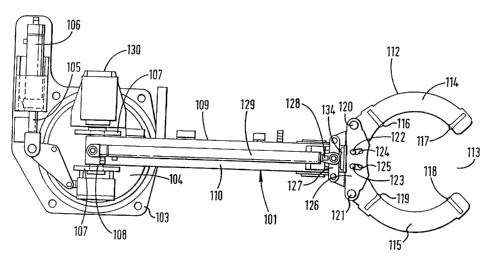
Referring to the drawings, there is shown a appara-
tus for aligning tubulars which is generally identified
by reference numeral 101. The apparatus 101 comprises
a
base 103 which can be conveniently be bolted to a der-
rick where required.
A rotor 104 is rotatably mounted on said base 103
and can be pivoted with respect to the base 103 by
extension and retraction of the piston 105 of a piston-
and-cylinder assembly 106 which is mounted fast on the
base 103.
Two ears 107 extend upwardly from the rotor 104 and
support a pivot pin 108 on which is mounted a telescopic
arm 109. The telescopic arm 109 comprises a first box
section 110 and a second box section 111 which is slid-
ably mounted in the first box section 110. A head 112
is
mounted on the end of the second box section 111 and
can
be opened to allow the entry of a tubular into opening
113. The head 112 comprises two arms 114, 115 each of
which is provided with two centring devices 116, 117,
118, 119 which can be moved radially inwardly and out-
wardly according to the diameter of the tubular to be
accommodated. As can be better seen in Fig. 2, each arm
114, 115 is pivoted on a respective pin 120, 121 and
is
' provided with a respective pin 122, 123 which can travel
within respective arcuate slots 124, 125 in a transverse
member 126.
The arms 114, 115 can be opened and closed by a
CA 02302231 2000-03-O1
WO 99/11902
- 6 -
PCT/GB98/02582
small hydraulic actuator 134 disposed beneath the trans-
verse member 126.
The transverse member 126 is connected to a cross
member 127 which is connected to the piston 128 of a
hydraulic piston-and-cylinder assembly 129, the other
end of which is connected to the first box section 110
over the rotational axis of the rotor 104.
A valve assembly 130 is mounted on the base 103
and is operable from a remote console to direct hydrau
lic fluid to and from the piston-and-cylinder assembly
106, the piston-and-cylinder assembly 129, the hydraulic
actuator 134 for opening and closing the arms 114, 115,
and a piston--and-cylinder assembly 131 which acts be-
tween a fitting I32 on the first box section 110 and a
fitting 133 on the rotor 104. Extension of the piston
and-cylinder assembly 131 displaces the telescopic arm
109 into an inoperative, upwardly extending position,
whilst contraction of the piston-and-cylinder assembly
131 moves the telescopic arm 109 to its operative, hori
zontal, position.
In use, the valve assembly 130 is controlled from a
remote console which is provided with a joystick which
is spring biased to a central (neutral) position. When
the operator displaces the joystick the valve assembly
130 controls the flow of hydraulic fluid to the ap-
propriate piston-and-cylinder assemblies. As soon as the
joystick is released the head 112 stops in the position
which it has obtained.
The description thus far relates to Applicants
existing apparatus.
The present invention differs from the aforede-
scribed apparatus in that the apparatus 101 includes
sensing devices for sensing the position of the head
112. In particular, a linear transducer, for example as
sold by Rota Engineering Limited of Bury, Manchester,
~ .
CA 02302231 2000-03-O1
WO 99/11902 PCT/GB98/02582
_ 7 _
England, is incorporated in both the piston-and-cylinder
assembly 129 and the piston-and-cylinder assembly 106.
The linear transducers provide a signal indicative of
the extension of both the respective piston-and-cylinder
assemblies 106,'129 which is transmitted to the opera-
tor's console.
At the commencement of a running operation the
telescopic arm 109 is lowered into a horizontal position
by contracting piston-and-cylinder assembly 131. The
arms 114 and 115 are then opened and the head 112
manoeuvred so that the arms 114 and 115 lie around the
tubular to be positioned. The arms 114 and 115 are then
closed.
The tubular is then manoeuvred into position above
and in alignment with a lower tubular held in slips.
The tubular is then lowered so that the pin enters the
socket and the joint is then made up in the usual
manner. When the tubular is in this position the
operator presses a button marked "memorise" on his
console.
After the slips have been released the tubulars are
lowered down the borehole and the slips re-set. The next
tubular is then in the proximity of the well centre,
either being suspended from an elevator or ready for
collection from a magazine mounted on the rig floor.
In either event the apparatus 101 is actuated so
that the head 112 encircles and grips the new tubular.
However, at this time the operator simply presses a
button on his console marked "recall". The telescopic
arm 109 then immediately moves to the memorized posi-
tion, this being achieved by a control system (not
shown) which displaces the piston-and-cylinder assembly
129 and the piston-and-cylinder assembly 106 until the
signals from their respective linear transducers equal
the signals memorized. The operator then checks the
CA 02302231 2000-03-O1
WO 99/11902
_ g _
PCT/CB98/02582
alignment of the tubulars. If they are correctly aligned
the upper tubular can be lowered and the tubulars se-
cured together. If they are not correctly aligned the
operator can make the necessary correction by moving the
joystick on his console. When the tubulars are correctly
aligned the operator can, if he chooses, update the
memorized position. However, he may omit this if he
believes that the deviation is due to the tubular not
being straight.
Various modifications to the embodiment described
are envisaged. For example if the tubulars are to be
collected from a fixed point the operator's console may
have a button for memorising the collection area. This
may be particularly appropriate if the tubulars are
stored on a rotating magazine alongside the slips. In
this case, the collection of the tubular and its posi-
tioning ready for stabbing can be very highly automated
with only minimal visual verification.
Whereas the position of the head is preferably
memorized electronically it could also be memorized
mechanically or optically.
The apparatus 101 described is designed so that
head 112 merely guides the tubular being stabbed with
the weight of the tubular being supported by an elevator
or similar device. However, it would be possible to
construct the apparatus 101 to take the entire weight of
the tubular. In this case it would be desirable to
include a device for raising and lowering the tubular to
facilitate the stabbing operation and, optionally,
modifying the head I12 to allow rotation of the tubular
whilst inhibiting vertical movement. Vertical adjustment
could conveniently be provided by hydraulic cylinders
between the base 103 and the rig floor or the de-rick on
which the apparatus 101 is mounted.
If desired the centring devices 116, 117, 118 and
CA 02302231 2000-03-O1
WO 99/11902 PCT/GB98/02582
_ g _
llg could be remotely adjustable to accommodate tubulars
of different sizes. Such an arrangement might also
include sensors to report the positions of the centring
devices.
In practice it is known that certain operators
appear to have a gift for making successful connections
quickly and efficiently. On observing these operators
it can be seen that they apply extremely personal com-
plex motions to the upper tubular as it is being inser-
ted into the socket. A second aspect of the present
invention contemplates recording these motions via the
sensing means and reproducing these motions during a
subsequent connecting operation. This procedure may be
applied in conjunction with or completely separate and
distinct from the method of aligning tubulars herein
before described.
25
.