Language selection

Search

Patent 2302556 Summary

Third-party information liability

Some of the information on this Web page has been provided by external sources. The Government of Canada is not responsible for the accuracy, reliability or currency of the information supplied by external sources. Users wishing to rely upon this information should consult directly with the source of the information. Content provided by external sources is not subject to official languages, privacy and accessibility requirements.

Claims and Abstract availability

Any discrepancies in the text and image of the Claims and Abstract are due to differing posting times. Text of the Claims and Abstract are posted:

  • At the time the application is open to public inspection;
  • At the time of issue of the patent (grant).
(12) Patent Application: (11) CA 2302556
(54) English Title: SNAP OVER-CAP FOR CONTAINER
(54) French Title: SURBOUCHON ENCLIQUETABLE POUR CONTENANT
Status: Deemed Abandoned and Beyond the Period of Reinstatement - Pending Response to Notice of Disregarded Communication
Bibliographic Data
(51) International Patent Classification (IPC):
  • B65D 41/16 (2006.01)
  • B65D 43/02 (2006.01)
(72) Inventors :
  • HEKAL, IHAB M. (United States of America)
(73) Owners :
  • IHAB M. HEKAL
(71) Applicants :
  • IHAB M. HEKAL (United States of America)
(74) Agent: RICHES, MCKENZIE & HERBERT LLP
(74) Associate agent:
(45) Issued:
(86) PCT Filing Date: 1998-09-03
(87) Open to Public Inspection: 1999-03-11
Examination requested: 2003-05-28
Availability of licence: N/A
Dedicated to the Public: N/A
(25) Language of filing: English

Patent Cooperation Treaty (PCT): Yes
(86) PCT Filing Number: PCT/US1998/018286
(87) International Publication Number: WO 1999011535
(85) National Entry: 2000-03-03

(30) Application Priority Data:
Application No. Country/Territory Date
60/057,486 (United States of America) 1997-09-03

Abstracts

English Abstract


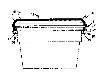
A plastic over-cap for a container includes a top section (10) and a
downwardly extending flange or skirt (18). At least one downwardly extending
leg (20) is integral with the flange (18) and a bottom edge (38) may be equal
with or extend below the lowermost edge (22) of the flange (18). The leg (20)
includes an internal engagement section (28) for snapping the over-cap onto
the rim of a container. The leg (20) is distinguished or separated from the
flange (18) by at least one slot (24) or a weakness line on one side thereof.
This configuration allows the leg (20) to flex outwardly for accommodating
variations in the rim diameter of the container, and facilitates removal of
the over-cap by children, elderly or those with arthritic conditions. Removal
is also aided by a cam surface (34) that engages an underside of the container
rim.


French Abstract

L'invention se rapporte à un surbouchon (OC) pour contenant (C) et notamment à un surbouchon en matière plastique comportant une partie supérieure (19) et une bride ou jupe (18) orientée vers le bas. Au moins une patte (20) en saillie vers le bas est intégrée à la bride (18) et un bord inférieur (38) peut arriver au niveau, ou faire saillie en dessous, du bord inférieur (22) de la bride (18). La patte (20) comporte une section d'accouplement interne (28) permettant d'encliqueter le surbouchon sur la bague d'extrémité d'un contenant. La patte est distincte de la bride ou séparée de cette dernière par au moins une fente (24) ou une ligne de fragilité sur un de ses côtés. Cette configuration permet à la patte (20) de fléchir vers l'extérieur pour compenser les variations de diamètre de la bague d'extrémité du contenant, et cela facilite en outre le retrait du surbouchon du contenant par des enfants, des personnes âgées et des personnes souffrant d'arthrite. Le retrait du surbouchon est également facilité par une surface inclinée (34) qui entre en contact avec une partie inférieure de la bague d'extrémité du contenant et qui assure ainsi le contact avec le contenant.

Claims

Note: Claims are shown in the official language in which they were submitted.


5
CLAIMS:
1. An over-cap for a container, said over-cap including an annular rim section
and a peripheral skirt portion depending therefrom, at least one leg section
extending
from said rim section and having separation means to distinguish said leg
section from
said skirt portion; means on said leg section for engaging a portion of an
associated
container, and means accommodating flexure of said leg section outwardly from
said
skirt portion for aiding in release of said over-cap from the container.
2. An over-cap as defined in claim 1 wherein said leg section includes a
radially
inwardly extending surface for camming said leg section outwardly upon
engagement
with a container rim.
3. An over-cap as defined in claim 1 wherein said leg section includes a notch
formed therein for receiving a container rim.
4. An over-cap as defined in claim 3 wherein said notch extends radially
inwardly and downwardly for being positioned beneath a container rim
5. An over-cap as defined in claim 2 wherein said leg section includes a notch
formed therein for receiving a container rim.
6. An over-cap as defined in claim 5 wherein said notch extends radially
inwardly and downwardly for being positioned beneath a container rim.
7. An over-cap as defined in claim 1 wherein said leg section is longer than
said peripheral skirt portion and includes a bottom edge that extends below a
lower
edge of said skirt portion.
8. An over-cap as defined in claim 1 including a plurality of leg sections
contained within said peripheral skirt portion and spaced about said rim
section, said
separation means comprising a plurality of slots for separating said leg
sections from
said skirt portion.

Description

Note: Descriptions are shown in the official language in which they were submitted.


CA 02302556 2000-03-03
WO 99/11535 PCT/US98/18286
"SNAP OVERLAP FOR CONTAINER"
FIELD AND BACKGROUND OF THE INVENTION
The present invention is directed to an over-cap for containers, and more
particularly to an over-cap which can accommodate large variations in the
major
diameter of a container rim.
Various types of over-caps for containers, such as plastic bowls or metal
cans,
are currently available. These caps typically include a peripheral section
which extends
downwardly in the form of a flange or skirt from the outer edge of the top
panel of the
cap. In the prior art, any downwardly extending peripheral section or flange
is
continuous and includes an internal section which may engage with the rim of
the
container and may be snapped thereon for closing or covering the container.
The
internal section is usually continuous around the internal periphery of the
over-cap or
might be interrupted. This type of over-cap design functions well with metal
containers, such as cans, since the major diameter of an opened can flange is
relatively
constant due to the high precision with which the metal flange can be made and
especially using the currently available seaming tools. An example of the
presently
available over-cap design is shown in FIG. 1.
The prior art design of an over-cap, as described above, suffers from the
disadvantage that when the over-cap is removed by pulling-up at one point on
the
downwardly extending flange, the over-cap, which is generally made of a
flexible
material such as plastic, tends to bind or pull inwardly against the rim of
the bowl or
flange of a can, at about 90 degrees from the pull point in either direction
around the
over-cap. As one can readily appreciate, this bending or flexing of the over-
cap would
tend to more tightly secure the over-cap on the container as opposed to
facilitating its
removal. Accordingly, the prior art design makes it difficult to remove the
over-cap
from its container, especially by children, the elderly and adults with
arthritic
conditions or the like. The removal of the over-cap is particularly difficult
if the
downwardly extending flange is relatively long.
In addition to the above, currently available over-caps do not work well with
containers that are made of plastic,' because large diameter variations are
normally
present as a result of the technological insufficiency to make the major rim
diameter
with tight tolerances. This is especially true if the container is subjected
to a high heat
and pressure environment, such as in a retort cooker.
In view of the disadvantages associated with the currently available over-cap
signs, there is a need in the industry for an over-cap which greatly
facilitates its
removal from the associated container and which can accommodate relatively
large

CA 02302556 2000-03-03
WO 99/11535 PCT/US98/18286
2
variations in the major diameter of a container, and especially those
containers made
from a plastic material.
OBJECTS AND SUMMARY OF THE INVENTION
The principal object of the present invention is to provide an over-cap which
overcomes the disadvantages associated with the currently available design.
Another object of the present invention is to provide an over-cap which makes
it
easy to remove the over-cap from an associated container, especially by
children, the
elderly and those with adverse medical conditions, such as arthritis.
Yet another object of the present invention is to provide an over-cap which
can
be easily snapped on and readily removed from an associated container without
requiring a major effort.
Still yet another object of the present invention is to provide an over-cap
which
can accommodate relatively large variations in the major diameter of the
container rim.
An additional object of the present invention is to provide an over-cap which
functions well with metallic as well as plastic containers.
In accordance with the above-noted objects, the present invention provides an
over-cap in which a downwardly extending peripheral flange is provided with
one or
more leg portions which include an internal engagement section for snapping on
to the
rim of an associated container. A slot or weakening line extends along at
least on one
side of the leg, which allows the leg to flex outwardly for accommodating
variations in
the rim diameter of the container. Preferably, in a preferred embodiment, the
over-cap
of the present invention is provided with three equidistantly positioned leg
portions
around the periphery thereof, and each leg is separated from the downwardly
extending
flange of the over-cap by a slot or weakening line on both sides thereof.
BRIEF DESCRIPTION OF THE DRAWINGS
The above and other objects and novel features of the present invention will
become apparent from a review of the detailed description of the preferred
embodiment
of the invention set forth below and as illustrated in the drawings, in which:
FIG. 1 is a perspective view of a prior art cap shown mounted on a container;
FIG. 2 is a perspective view of an over-cap of the present invention shown
mounted on a container;
FIG. 3 is an elevational view of the over-cap of the invention;
FIG. 4 is a sectional view of the over-cap taken along line 4-4 of FIG. 2;

CA 02302556 2000-03-03
WO 99111535 ~ PCT/US98/18286
3
FIG. 5 is a sectional view of the over-cap in FIG. 4, shown mounted on a
container (the container being shown by phantom lines); and
FIG. 6 is an enlarged, fragmentary view showing details of the portion circled
in FIG. 4.
DETAILED DESCRIPTION OF THE PREFERRED EMBODIMENT
As is best shown in FIG. 2, the over-cap OC of the present invention includes
a
top section 10, made of a flexible plastic material, and a central section 12.
The central
section 12 may be formed of plastic and be integrally molded with top section
10 but
may, preferably, be made of a variety of paper or like material and when of
different
material may be adhesively secured to the over-cap or be received in a
peripheral
groove 14 in top section 10 (see FIGS. 4-5). Although not shown, a printed
label, or
the like, substantially corresponding in size to the central section 12, may
be provided
thereon to convey information to customers and prospective consumers regarding
the
product contained in container C.
The top section 10 includes an annular rim section 16 and integral, downwardly
extending peripheral flange, or skirt, portions, 18. The top section 10
further includes
at least one, and preferably three legs or leg sections 20 integrally
connected therewith
and with a flange portion 18. As is best shown in FIGS. 3 and 4, each leg 20
may
extend below the lowermost edge 22 of a flange 18; however, it is to be
understood
that the legs .20 may have their lower edge portions co-terminous with the
lower edge
portions of the flange, or skirt, 18. Such a modification can be easily
achieved by either
shortening the legs 20 or by extending the peripheral flange, or skirt, 18.
Although
integral with the top section 10 and flange 18, legs 20 are separated from
flange 18 by a
line of separation, which may be in the form of a vertical slot 24 on either
side, or both
sibs, of each leg 20. It is noted herewith that although one separation line
in the form
of a slot on each side of legs 20 is illustrated in the drawings, it is within
the scope of
this invention to provide only one slot, or a weakness line, or a functionally
equivalent
division on either side of the legs 20. The main function of providing a
wealoiess line
or a slot is to allow the legs to flex outwardly to accommodate variations in
the
diameter of a container rim, or to facilitate removal of over-cap OC from
container C
by a user. A line of weakness, rather than a through slot at 24, will also
serve as a
tamper evidence indicator, if such a feature is appropriate or desired.
As is best shown in FIG. 3, legs 20 are equidistantly located about the
periphery
of flange 18. In this regard, it is noted that the number of legs, and their
lengths and
locations about the flange 18 may be varied and fall within the scope of this
invention.

CA 02302556 2000-03-03
WO 99/11535 PCT/US98/18286
4
In order to snap the over-cap OC onto a container rim 26 (FIG. 5), legs 20 are
provided with an engagement section 28 on an inner surface 30 thereof, as is
best
shown in FIGS. 4 and 6. Also, as shown in FIG. 6, engagement section 28
includes a
continuous notch 32 including a radially, inwardly extending, beveled cam
surface 34.
and a radially inwardly extending beveled surface 36 extends upwardly fmm the
bottom
edge 38 of leg 20.
As one of ordinary skill in the art would appreciate, when over-cap OC is
snapped onto container C, container rim 26 would be received in notch 32. In
this
position, the cam surface 34 would abut lower section 40 of container rim 26,
thereby
securing the over-cap OC onto the container C.
Any one of the several legs 20 can be grasped and flexed outwardly, as shown
by arrow X in FIG. 5, to remove over-cap OC from container C. One of ordinary
skill
in the art would appreciate that when leg 20 is flexed outwardly, cam surface
34 would
no longer abut lower section 40 of rim 2b, thereby facilitating removal of the
over-cap
OC from container C.
One of ordinary skill in the art would further appreciate that the provision
of
cam surface 34 makes it easy to remove the over-cap from the container C even
if the
over-cap is removed by pulling it upwardly without first flexing any of the
legs. As
shown in FIGS. 5 and 6, if the over-cap is pulled directly upwardly at any of
the legs
20, the lower section 40 of rim 26 would slide down along the cam surface 34
and,
because surface 34 extends downwardly and inwardly, it would function as a cam
to
automatically flex leg 20 outwardly, as the container rim 26 slides down along
surface
34.
As can be observed from the foregoing descriptions, the over-cap of the
present
invention overcomes the disadvantages associated with the heretofore available
caps and
greatly facilitates removal of an over-cap from an associated container.
While the invention has been described as having a preferred design, it is to
be
understood that the invention is capable of further modifications, uses and/or
adaptations following in general the principle of the invention, and including
such
c~partures from the present disclosure as those that come within the known or
customary practice in the art to which the invention pertains, and as may be
applied to
the central features herein set forth and fall within the scope of the
invention as defined
in the appended claimed subject matter.

Representative Drawing
A single figure which represents the drawing illustrating the invention.
Administrative Status

2024-08-01:As part of the Next Generation Patents (NGP) transition, the Canadian Patents Database (CPD) now contains a more detailed Event History, which replicates the Event Log of our new back-office solution.

Please note that "Inactive:" events refers to events no longer in use in our new back-office solution.

For a clearer understanding of the status of the application/patent presented on this page, the site Disclaimer , as well as the definitions for Patent , Event History , Maintenance Fee  and Payment History  should be consulted.

Event History

Description Date
Inactive: Dead - No reply to s.30(2) Rules requisition 2007-01-12
Application Not Reinstated by Deadline 2007-01-12
Deemed Abandoned - Failure to Respond to Maintenance Fee Notice 2006-09-05
Inactive: IPC from MCD 2006-03-12
Inactive: Abandoned - No reply to s.30(2) Rules requisition 2006-01-12
Letter Sent 2005-10-03
Reinstatement Requirements Deemed Compliant for All Abandonment Reasons 2005-09-22
Deemed Abandoned - Failure to Respond to Maintenance Fee Notice 2005-09-06
Inactive: S.30(2) Rules - Examiner requisition 2005-07-12
Amendment Received - Voluntary Amendment 2003-09-11
Letter Sent 2003-06-26
Request for Examination Requirements Determined Compliant 2003-05-28
All Requirements for Examination Determined Compliant 2003-05-28
Request for Examination Received 2003-05-28
Inactive: Cover page published 2000-05-12
Inactive: First IPC assigned 2000-05-11
Inactive: Notice - National entry - No RFE 2000-04-26
Application Received - PCT 2000-04-19
Application Published (Open to Public Inspection) 1999-03-11

Abandonment History

Abandonment Date Reason Reinstatement Date
2006-09-05
2005-09-06

Maintenance Fee

The last payment was received on 2005-09-22

Note : If the full payment has not been received on or before the date indicated, a further fee may be required which may be one of the following

  • the reinstatement fee;
  • the late payment fee; or
  • additional fee to reverse deemed expiry.

Please refer to the CIPO Patent Fees web page to see all current fee amounts.

Fee History

Fee Type Anniversary Year Due Date Paid Date
Basic national fee - standard 2000-03-03
MF (application, 2nd anniv.) - standard 02 2000-09-05 2000-03-03
MF (application, 3rd anniv.) - standard 03 2001-09-04 2001-08-24
MF (application, 4th anniv.) - standard 04 2002-09-03 2002-08-22
Request for examination - standard 2003-05-28
MF (application, 5th anniv.) - standard 05 2003-09-03 2003-05-28
MF (application, 6th anniv.) - standard 06 2004-09-03 2004-08-23
MF (application, 7th anniv.) - standard 07 2005-09-06 2005-09-22
Reinstatement 2005-09-22
Owners on Record

Note: Records showing the ownership history in alphabetical order.

Current Owners on Record
IHAB M. HEKAL
Past Owners on Record
None
Past Owners that do not appear in the "Owners on Record" listing will appear in other documentation within the application.
Documents

To view selected files, please enter reCAPTCHA code :


To view images, click a link in the Document Description column. To download the documents, select one or more checkboxes in the first column and then click the "Download Selected in PDF format (Zip Archive)" or the "Download Selected as Single PDF" button.

List of published and non-published patent-specific documents on the CPD .

If you have any difficulty accessing content, you can call the Client Service Centre at 1-866-997-1936 or send them an e-mail at CIPO Client Service Centre.


Document
Description 
Date
(yyyy-mm-dd) 
Number of pages   Size of Image (KB) 
Representative drawing 2000-05-12 1 5
Cover Page 2000-05-12 1 54
Abstract 2000-03-03 1 53
Description 2000-03-03 4 253
Claims 2000-03-03 1 42
Drawings 2000-03-03 2 55
Notice of National Entry 2000-04-26 1 193
Reminder - Request for Examination 2003-05-06 1 113
Acknowledgement of Request for Examination 2003-06-26 1 173
Courtesy - Abandonment Letter (Maintenance Fee) 2005-10-03 1 173
Notice of Reinstatement 2005-10-03 1 165
Courtesy - Abandonment Letter (R30(2)) 2006-03-23 1 166
Courtesy - Abandonment Letter (Maintenance Fee) 2006-10-31 1 175
PCT 2000-03-03 6 251
Fees 2003-05-28 1 32
Fees 2001-08-24 1 40
Fees 2002-08-22 1 36
Fees 2005-09-22 1 38