Note: Descriptions are shown in the official language in which they were submitted.
CA 02302631 2000-03-06
1
r
SPECIFICATION
WET-TYPE SPRINKLER SYSTEM
FIELD OF THE INVENTION
This invention relates to an automatic extinguisher
system for buildings, etc., and more particularly to a wet-
type sprinkler system of which secondary pipelines are
filled with water in a normal condition.
BACKGROUND ART
Hitherto, sprinkler systems are in widespread use in
buildings, especially in large-scale buildings. In known
sprinkler systems, sprinkler heads for fire-extinguish
purpose are arranged on ceilings of buildings. The
sprinkler system is composed essentially of the sprinkler
heads each of which is individually actuated in response to
an ambient thermal condition, a feed pump as a water supply
unit, and a feed pipe arrangement including primary
pipelines and secondary pipelines.
The primary pipelines) of the feed pipe arrangement
is arranged in a manner perpendicularly rising from the
feed pump, to reach the heights of floors. The secondary
pipelines are connected to the primary pipeline such that
water flows through the pipelines. The secondary
pipelines) generally extends in the horizontal direction
- CA 02302631 2000-03-06
2
on each floor, and then it is branched and hung-down in the
almost perpendicular direction to form hang-down pipe
portions, which respectively communicate with the sprinkler
heads.
The sprinkler systems with such structures as
mentioned above are divided into wet-type sprinkler systems
and dry-type sprinkler systems. These two types of the
system are different in the following point: That is, in
the former type, not only the primary pipelines but also
the secondary pipelines are filled with water, and this
state is called "normal condition". On the other hand, in
the latter type, the secondary pipelines are not filled
with water, i.e. they are filled with air (in other words,
only the primary pipeline is filled with water).
In the known wet-type sprinkler system, water
charged in the secondary pipelines in the same manner as in
the primary pipeline is constantly kept pressurized, e.g.
- at 7 to 8 kgf/cmZ. By this setting, the system has an
advantage in that water discharge is quickly performed when
the sprinkler head is actuated at the breaking out of fire.
In general cases, however, the opening and shutting of the
sprinkler heads are controlled not systematically but
individually at the ceiling portions at which the sprinkler
head are arranged. For example, when a sprinkler head is
exposed to heat, a sealed portion thereof is melted, and
the sprinkler head comes ready to jet water. Accordingly,
~~ CA 02302631 2000-03-06
3
in the event that the sprinkler head is actuated on an
occasion other than an actual fire, for instance failure of
the system or intentional destruction of the same, there is
an inconvenience that pressurized water is instantly
injected to drench the area around the sprinkler head. For
example, when the sprinkler head functions in a wrong way
in an office building, documents, computers, elevator
systems, etc. have incurred a huge amount of damage.
To cope with the inconvenience, a wet-type sprinkler
system having an additional function of a so-called
preliminary operation has been employed. The above-
mentioned sprinkler system is provided with a valve section
between the primary pipeline and each secondary pipeline.
The valve section is caused to normally be closed, and the
valve is opened by a control section of the system only
when the control section receives a fire-detection signal
from a fire sensor (which functions more quickly than the
- sprinkler head), followed by feeding a large volume of
high-pressure water to the secondary pipelines as the
preparation for actuating sprinkler heads.
This system only allows water in the secondary
pipeline to be discharged in the event of wrong-way-
function of the sprinkler heads, and therefore damage can
be minimized compared with the prior system. However, the
water in the secondary pipeline alone still causes a
considerable amount of damage.
' . CA 02302631 2000-03-06
4
On the other hand, the dry-type sprinkler system has
been developed to eliminate such damage. Namely, in this
system, the secondary pipeline is filled with air which is
_ pressurized at about 2 kgf/cmz, in place of water.
Therefore, even if the sprinkler head undergoes a failure,
only air is discharged, so that damage caused by water can
be avoided. This is the largest advantage of the dry-type
sprinkler system.
The dry-type sprinkler system requires a work of
dewatering or draining the secondary pipe when water
injection is carried out on trial. Even after the
dewatering work, however, not a little volume of water
remains in the hang-down pipe portions if each of the
sprinkler heads is not actuated. As a result, it tends
that the hang-down pipe portion in the vicinity of a
boundary between water and air corrodes, and the corrosion
once obtained easily spreads resulting in perforation. To
eliminate the corrosion, periodical maintenance and repair
are required, or a pipe formed of a special material
becomes indispensable, and therefore the defrayal on a
managing company is not small.
Further, there is such a tendency that a very small
volume of air leaks at a junction of the pipelines, etc.,
compared with the case where water is stored, so that
decrease in pressure of air is relatively fast, which
requires frequent addition of air into the secondary
CA 02302631 2000-03-06
S
pipelines by means of a compressor or the like. The
supplement of air, however, disadvantageously brings about
supply of oxygen, thereby promoting the formation of rust.
Still further, when water injection for actually
extinguishing fire is carried out, water pressurized at
about 7 to 10 kgf/cm2 flows from the feed pump into the
secondary pipelines upon opening of the valve section. If
air remains at the corners or upper portions in the
pipeline, however, an effective cross section of flowing
water in the pipeline is reduced, which can unfavorably
prevent water from flowing.
Even further, when water highly pressurized by the
feed pump is supplied to the sprinkler heads which have not
yet been actuated, air stored therein beforehand is
compressed to become high pressure air, thereby causing
such a danger that elastic force of the high pressure air
can blow off components of the sprinkler heads. In
addition, when a fire actually breaks out, water cannot be
discharged until the charged air is completely drawn off.
As a result, it is pointed out that the dry-type sprinkler
system is inferior to the wet-type sprinkler system in
immediacy at an initial extinguishing operation which is
the essential object of sprinkler systems
To cope with the various inconveniences of the known
sprinkler systems, particularly to enhance a rust
prevention performance, an extinguishing fixture is
CA 02302631 2000-03-06
6
proposed, for example, in Japanese Patent Kokai Publication
Hei 10(1998)-234881. According to the extinguishing
fixture, in place of air, inert gas is charged in a pipe
~ portion of the secondary pipeline, at a location
immediately above the sprinkler heads of the wet-type
sprinkler system. By using inert gas such as nitrogen gas,
rusting and development thereof can be effectively
prevented in both the wet-type sprinkler system and the
dry-type sprinkler system.
Further, there is disclosed a water flow detecting
system for a wet-type sprinkler system, for example, in
Japanese Patent Kokoku Publication No. Hei 7(1995)-12382,
in which fluid in the secondary pipelines is brought to
have a low pressure (but not negatively pressurized) than
water in the primary pipelines. In this case, if a fire
actually breaks out, the low-pressure water in the
secondary pipelines is immediately discharged, so that it
is considered that this system is effective for initial
extinguishing operation.
However, in the above mentioned extinguishing
fixture disclosed in Japanese Patent Kokai Application Hei
10(1998)-234881, in which inert gas has been charged, if
the sprinkler head is actuated in a relatively small and
tightly closed room, nitrogen gas fills the room, whereby
the room undergoes oxygen deficiency, which can adversely
affect safety.
CA 02302631 2001-05-29
7
Further, according to the invention disclosed by
Japanese Patent Kokoku Publication No. Hei 7(1995)-12382,
the immediacy of the initial extinguishing operation can be
ensured. However, water is pressurized although the
pressure degree is low. Therefore, damage caused by water
injection is not avoidable when sprinkler heads function in
a wrong way.
The present invention is~proposed to eliminate the
above inconveniences, and an object of the invention is to
provide a wet-type sprinkler system which is capable of
preventing damage to be caused by water when a sprinkler
head functions in a wrong way, with ensuring to quickly
perform an initial extinguishing operation of sprinkler
heads at an actual fire.
DISCLOSURE OF THE INVENTION
To attain the above mentioned object, a wet-type
sprinkler system according to claim 1 of the present
invention has a negative-pressure-securing unit for
maintaining water charged in at least one secondary
pipeline of a feed pipe arrangement in a negatively
p r a s s a r i z a d . This negatively pressurized state is considered as a
normal
condition, namely "ready state", in the present invention.
As a result, even if sprinkler heads which are
individually actuated in a wrong way to given an open state,
water in the secondary pipeline can be prevented from being
CA 02302631 2000-03-06
8
erroneously discharged, from the sprinkler heads. In other
words, water in the secondary pipeline is maintained in the
negatively pressurized state, so that air may be drawn into
the opened sprinkler heads but water can never be injected
from the sprinkler heads.
When a fire actually breaks out, a control section
receives a fire-detection signal from a fire sensor, and
causes a valve section to be opened and a water supply unit
to start operation. Thus, water is conveyed from at least
one primary pipeline to the secondary pipeline, whereby the
pressure in the secondary pipeline is changed from the
negatively pressurized state to a positively pressurized
state. The system in such a preparatory movement (by the
attainment of the valve opening) jets water through
sprinkler heads by means of individual opening movements
thereof.
In a wet-type sprinkler system as claimed in claim 2,
y there are provided a suction pipe communicating with the
secondary pipeline of the feed pipe arrangement at a top
part thereof, the secondary pipeline forming a water supply
line from the water supply unit to the sprinkler heads, and
a suction unit for sucking the internal part of the
secondary pipelines which is provided at a top part of the
secondary pipelines, the suction pipe and the suction unit
forming the negative-pressure-securing unit. The water
stored in the secondary pipeline which is normally filled
CA 02302631 2000-03-06
9
with water is negatively pressurized due to the suction
operation of the suction unit, and the negatively
pressurized state is considered as a normal condition.
As a result, the negative-pressure-securing unit
with a simple structure surely functions.
A wet-type sprinkler system as claimed in claim 3
comprises a water level detecting unit arranged at a top
part of the secondary pipeline for detecting a water level
in the secondary pipeline, wherein the control section
controls the water supply unit and the opening and shutting
of the valve section when the water level becomes lower
than a predetermined level in response to a signal supplied
from the water level detecting unit, to supply water from
the primary pipeline to the secondary pipeline section.
By virtue of this construction in addition to the
function as claimed in claim 1, the level of water in the
secondary pipeline, which is negatively pressurized and
" accordingly likely to evaporate, can always be kept,
whereby immediacy of the fire extinguishing system can be
maintained.
Subsequently, the a wet-type sprinkler system as
claimed in claim 4 has such a function that the control
section controls the valve section so as to be opened only
when the control section receives the fire-detection signal
a plurality of times within a predetermined time period.
By virtue of this structure, in addition to the
~' CA 02302631 2000-03-06
function as claimed in claim l, it becomes possible to
effectively prevent the secondary pipeline from being
unnecessary relieved from the negatively pressurized state
r then to be positively pressurized by a mere wrong-way-
5 function of the fire detecting unit.
According to a wet-type sprinkler system as claimed
in claim 5, the suction pipe of the negative-pressure-
securing unit is provided with a negative-pressure-
regulating member for canceling excessive negative pressure
10 of water caused by the suction operation of the suction
unit. As a result, the pressure of water can be increased
before the sucked water is brought to have an excessively
negative pressure and accordingly evaporates to cause
cavitation.
In a wet-type sprinkler system as claimed in claim 6,
the negative-pressure-regulating member in claim 5 are
implemented as a vacuum breaking valve which functions to
increase the pressure of water, when the negative pressure
becomes lower than a predetermined value. The vacuum-
breaking valve has a single function for which troublesome
setting is not necessary, whereby the negative pressure
regulation can be achieved with a minimum cost without fail.
BRIEF DESCRIPTION OF THE DRAWINGS
Fig. 1 is a schematic diagram for showing the
outline of a wet-type sprinkler system according to a first
CA 02302631 2000-03-06
11
embodiment of the invention;
Fig. 2 is a block diagram showing the essential
components of the wet-type sprinkler system of Fig. 1;
Fig. 3 is a diagram for showing a state of the wet-
s type sprinkler system of Fig. 2, when a fire has broken
out;
Fig. 4 is a diagram for showing a state of the wet-
type sprinkler system of Fig. 2, when a sprinkler head of
the wet-type sprinkler system functioned in a wrong way;
and
Fig. 5 is a descriptive drawing for showing an
example of the structure of the sprinkler head applicable
to the system of the invention.
BEST MODE FOR CARRYING OUT THE INVENTION
The invention will now be described in detail with
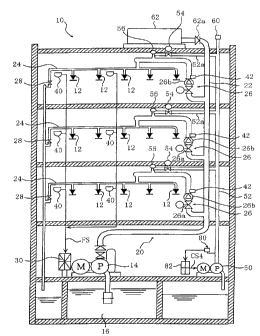
referring to embodiments thereof. Fig. 1 shows the outline
of a wet-type sprinkler system 10 as a first embodiment of
the invention. As shown in the figure, the wet-type
sprinkler system 10 is essentially composed of a fire
extinguishing water tank 16, a feed pump 14, a feed pipe
arrangement 20, and sprinkler heads 12.
The fire extinguishing water tank 16 is located at
an undermost portion of a building, for instance, at a
basement, which stores a sufficient volume of water by that
water discharge can be carried out over a long time period
CA 02302631 2000-03-06
12
from a number of sprinkler heads 12 on each floor of the
building. The feed pump 14 functions as a water supply
unit, and is selected from those which can continuously
discharge water in an amount of 80 liters or more per min
simultaneously from each of the 8 to 40 sprinkler heads
even under water-flow resistance when transmitted to the
pipe arrangement.
The feed pipe arrangement 20 is composed of a
primary pipelines) 22, valve sections 26, and secondary
pipelines 24, and forms a water supply line from the feed
pump 14 to the sprinkler heads 12. The primary pipeline 22
is formed as a feed pipe which is raised in an
approximately perpendicular direction from the feed pump 14
to an uppermost floor of the building or the like and
branched off on each floor. The diameter of the pipes
forming the primary pipeline is selected to be large so as
to meet a huge volume of water discharge from the feed pump
14.
Fig. 2 is a block diagram for showing the
construction of the essential parts of the wet-type
sprinkler system 10 of Fig. 1. As shown in the figure, the
valve section 26 is connected to an upper end portion of
the primary pipeline 22 which is branched off on each floor,
at the feed pump side as water pass therethrough. The
valve section 26 is composed of an electric valve 26a and
an alarm valve 26b. The electric valve 26a is kept closed
' CA 02302631 2000-03-06
13
in a normal condition, which will be described hereinafter
relating to it's function. The alarm valve 26b has a
function of giving an alarm when the electric valve 26a is
opened and at the same time water discharge are carried out
over a predetermined time period.
The secondary pipeline 24 has one end connected to
the valve section 26, giving communication therebetween,
and extends in parallel with the other secondary pipelines
of other floors. Then, the secondary pipeline 24 is
further branched off, and each of the branched portions
hangs down in the perpendicular direction, thereby forming
a hang-down pipe portion 24b. The hang-down pipe portion
24b has an end thereof to which is attached the sprinkler
head 12 exposed from a ceiling portion on each floor. The
secondary pipeline 24 does not need to be so large in
diameter as the primary pipeline 22, and a pipe forming the
secondary pipeline can be freely selected from those which
are sufficient, in diameter, material and thickness, to
resist a predetermined pressure condition, which will be
hereinafter described. There is provided a test valve 28
on the secondary pipeline 24 at a lower end thereof, which
is opened for discharging water on trial or for initially
introducing water into the pipelines.
The sprinkler head 12 has a large number of
injection holes (not shown) formed in an end surface
thereof. The injection holes are normally closed, whereas
CA 02302631 2000-03-06 '~"''
14
the sprinkler head 12 individually has a function of
opening the injection holes to jet water or the like when
ambient temperature rises to a predetermined high value,
e.g. to 80 °C. To open the injection holes, a high-
s temperature softening property of a metal having a low
melting point is employed in general, but any other
structure or component is applicable insofar as the above-
mentioned function can be achieved. The sprinkler heads 12
having the function as mentioned above are respectively
connected to the distal ends branched from the secondary
pipeline 24 of the feed pipe arrangement 20.
In addition to the above described structure, the
wet-type sprinkler system 10 of this embodiment is provided
with a fire sensor 40 and a control panel 30, both of which
achieve a preparatory movement, and further includes
"suction unit" and "water level detecting unit" arranged in
the secondary pipeline 24 as characteristic points.
The fire sensor 40, as a fire-state detection unit,
is provided on each floor. The sensor 40 has a function of
detecting smoke, flames, and ambient temperature with a
high sensitivity and at a high speed, thereby supplying a
fire-detection signal FS to the control panel 30 when the
ambient temperature reaches a predetermined high
temperature. The fire sensor 40 is selected from those
which can detect the ambient temperature etc. more quickly
than the sprinkler heads 12.
CA 02302631 2000-03-06
The control panel 30 functions as a control section
of the system. The control panel 30 has an input block
which can receive various signals from the outside, a
K determining block composed of a memory, a relay circuit,
5 etc. which are operated according to a preset control
theory, and an output block which generates control signals
to each of the valves and the feed pump 14 and supplies
power to the same. With this structure, the control panel
30 carries out determination, based on the fire-detection
10 signal FS transmitted from the fire sensor 40, thereby
controlling the opening degree, open/closed states, etc. of
each valve.
As understood from Fig. 1 as well, the "suction
unit" as a characteristic structure of the present
15 invention is composed of a suction pump 50, a suction pipe
52, and a drawing electromagnetic valve 54 in this
embodiment. More specifically, the suction unit is
.. composed of the suction pipe 52 of which one end
communicates with a raised branch pipe 24a of the secondary
pipeline 24, as formed being raised from the uppermost
portion of the secondary pipeline 24, extends to an
approximately horizontal direction, and further extends in
a hang-down manner over a predetermined length; the drawing
electromagnetic valve 54 arranged across the roughly
horizontal portion of the suction pipe 52; and the suction
pump 50 arranged at a lower end of the suction pipe 52.
,w,~
CA 02302631 2000-03-06
16
The suction pump 50 may be of any type insofar as it
is arranged at a lower location of the building wherein the
- suction pump 50 absorbs liquid such as water or gas such as
air, and has capacity sufficient to maintain the secondary
pipeline 24 on each floor to have a predetermined negative
pressure of water. The drawing electromagnetic valve 54 is
controlled to be opened and closed in response to the
control signal from the output block of the control panel
30.
Further, in the "water level detecting unit", with a
characteristic structure, of the present invention, a water
level detector 56 having two electrodes 56a is arranged in
the raised branch pipe 24a in this embodiment by way of an
example. In the water level detector 56, a predetermined
electric potential is given to the electrodes 56a, and an
energized state across the electrodes 56a is detected in a
binary form, followed by supplying the signal indicative of
the detected binary value to the control panel 30. More
specifically, when the ends of the two electrodes 56a are
in contact with water, an energized state are obtained by
the two electrodes, whereas when the ends are separated
from water, the energized state are not obtained.
Accordingly, the detector 56 detects the change of the
energized state and non-energized state as a change of a
water level within the secondary pipeline 24, and outputs
the change as a binary signal.
,.-,.
CA 02302631 2000-03-06
17
Further, as shown in Figs. 1 and 2, the wet-type
sprinkler system 10 is provided with a pressure switch 42
for detecting fluctuations of the pressure within the
secondary pipeline 24.
Description will now be made as to the function of
the system as an embodiment, which has the above-described
structure. Fig. 3 shows a state of the wet-type sprinkler
system 10 of Fig. 2 in the case where a fire has actually
broken out.
First of all, the feed pipe arrangement 20 is filled
with water in an initial state. The operator of the system
opens each of the valves except the drawing electromagnetic
valve 54, and causes the feed pump 14 to drive, whereby
water is conveyed from the fire extinguishing water tank 16
into the feed pipe arrangement 20 to fill the same. Then,
the electric valves 26a and the test valves 28 are closed
to halt the operation of the feed pump 14. Thus, the
primary pipelines 22 and the secondary pipelines 24 are
filled with water at a high pressure for instance, of 8
kgf/cm2.
Then, the operator opens the drawing electromagnetic
valve 54, and causes the suction pump 50 to be driven,
whereby the internal gas of the suction pipe 52 and the
secondary pipelines 24 are sucked. At this time, all of
the end portions are closed, except those of the raised
branch pipes 24a which form the uppermost portions of the
CA 02302631 2001-05-29
18
secondary pipelines 24. Therefore, water stored in the
secondary pipelines 24 is not affected by back pressure of
the atmospheric air, and kept at a pressure lower than the
atmospheric pressure according to a suction force of the
suction pump 50 and therefore in a negatively pressurized
state, by which water remains in the secondary pipeline 24.
The above-mentioned suction operation by the suction
pump 50 is carried out even if the water level in the
raised branch pipe 24a is lower than a location of an
opening of a horizontal part 52a of the suction pipe, having
the drawing electromagnetic valve 54 as shown in Fig. 2
Water in the secondary pipelines 24 can
be negatively pressurized by the suction operation by means
of the suction pump 50.
After obtaining a negative pressure, the operator
observes the state of a signal from the water level
detector 56. Having confirmed that the water level is in
the vicinity of the electrodes 56a, i.e. water is
maintained to have the level which is sufficient to
generate the energized state, the operator stops the drive
of the suction pump 50. Then, the drawing electromagnetic
valve 54 is kept open, thereafter the suction pump 50 is
automatically operated and controlled by means of a vacuum
switch 80 arranged on the suction pipe 52, so as to
CA 02302631 2000-03-06
19
maintain a predetermined negative pressure of, e.g. -0.4
kgf/cm2 to -0.5 kgf/cm2. More specifically, a pump control
- block 82 supplies a control signal CS4 for controlling the
drive of the suction pump 50 in response to a signal from
the vacuum switch 80. These sequential operations form the
initial state, and then the system is transferred to a fire
monitoring state.
In this manner, the secondary pipeline 24 is
sufficiently filled with negative pressure water, so that
the rust preventive performance therein is enhanced. As a
result, perforation etc. caused by rusting can be prevented,
which frequently occurs in known systems at the hang-down
pipes 24b at parts in contact with the air.
The water negatively pressurized within the
secondary pipeline 24 has a lowered boiling point, which
leads to quick evaporation, and therefore the volume of
water is easily reduced and the water level is likely to
drop. To cope with this, if the control panel 30 receives
a signal LS indicative of water level drop (non-energized
state) from the water level detector 56, it outputs a
control signal CS2 from its output block to the valve
section 26, whereby water is added by slightly opening the
electric valve 26a. As a result, the water is always
maintained to have the same level as that of the initial
state. By maintaining the water level to the highest, the
instantaneous operability of the fire extinguishing system
CA 02302631 2000-03-06
' 20
is ensured. In regard to this, the addition of pressurized
water to the primary pipeline 22 is carried out by
supplying water from an auxiliary water tank 62 placed on a
roof portion in place of the drive of the feed pump 14.
In the fire monitoring state, the fire sensors 40
each monitor whether or not a fire has broken out, at
respective predetermined locations on each floor. In case
of a fire occurring at one of the locations, the fire
sensor 40 senses a fire state, and supplies the fire-
detection signal FS to the control panel 30.
The control panel 30 which has received the fire-
detection signal FS by way of the input block, supplies the
control signal CS2 by way of the output block for driving
the electric valve 26a on the floor of the fire sensor 40
which has sensed the fire state. Thus, the electric valve
26a is opened. Further, the control panel 30 supplies a
control signal CS1 to the drawing electromagnetic valve 54
simultaneously with the output of the signal CS2. Upon the
receipt of the signal, the drawing electromagnetic valve 54
is closed, whereby it is separated from the suction unit on
the secondary side. Simultaneously, the control panel 30
supplies a control signal CS3 to the feed pump 14 for
activating the same, whereby the feed pump 14 is driven.
As shown in Fig. 3, a preparatory movement is
carried out wherein a large volume of pressurized water
stored in the primary pipeline 22 flows into the secondary
CA 02302631 2000-03-06
21
pipeline 24 on the floor on which the fire has broken out,
and therefore the water which has been negatively
n pressurized in the secondary pipeline 24 is brought to have
a highly pressurized state of the level of, e.g. 6 kgf/cm2.
Subsequently, when one of the sprinkler heads 12 is
actuated due to exposure to heat caused by a fire at the
initial stage, the high-pressure water in the secondary
pipeline 24 is instantly injected from the sprinkler head
12 to start an extinguishing operation.
By the injection of the water from the sprinkler
head 12, the sprinkler system is in a water-running state
in which water is continuously supplied from the primary
pipelines) 20 to the secondary pipelines) 24. The above
sequential operations cause the sprinkler head 12 to
continuously inject a large volume of water.
The continuous water discharge eliminates a
possibility of injecting compressed air, and therefore
inconveniences such as scattering of the components of the
sprinkler head 12 can be dispensed with, which could occur
if high-pressure air was jetted.
Then, the person who takes care of the system
confirms that the extinguishing operation by the sprinkler
has been completed, and closes the electric valves) 26a,
followed by halting the feed pump 14. Thereafter, the
sprinkler head 12 which has been operated is replaced by a
new one, then every part of the system is examined, and
CA 02302631 2000-03-06
22
finally the system is reset to the initial state.
Fig. 4 is a descriptive drawing showing a state in
which the sprinkler head 12 of the wet-type sprinkler
system 10 of Fig. 2 functions in a wrong way. In the fire
monitoring state, when the sprinkler head 12 is damaged or
functions in a wrong way, the wet-type sprinkler system 10
of this embodiment works in the following manner. In this
state, the fire-detection signal FS is not output from the
fire sensor 40.
Due to the wrong-way-function of the sprinkler head
12, the water-injection holes on the end surface of the
sprinkler head 12 are opened, and the secondary pipeline 24
is opened to the air. The system of the present invention,
however, maintains water in the secondary pipeline 24 with
a negative pressure.
Accordingly, water is not come out from the
sprinkler head 12, whereby damage by water is not caused by
the wrong-way-function of the sprinkler head 12. Further,
as shown in Fig. 4, water stored in the secondary pipeline
24 is exposed to the atmospheric pressure through the
water-injection holes of the sprinkler head 12 and the
water moves toward the suction pipe 52 which is kept at the
negative pressure by the suction force. Namely, water in
the secondary pipeline 24 passes through the drawing
electromagnetic valve 54 which has been opened beforehand,
and is drawn toward the suction pump 50.
CA 02302631 2001-05-29
23
The pressure switch 42 detects fluctuations of
pressure within the secondary pipeline 24 occurring at this
water drawing. Then, the pressure switch 42 outputs a
signal AS indicative of occurrence of the wrong-way-
function to the control panel 30. The person who takes
care of the system confirms this state by observing the
control panel 30, and then examines the sprinkler head 12
and exchanges the one which is out of order for a normal
one. Therefore, damage by unnecessary water jet is not
caused, and the system can be reset to the initial state
after the examination of components. In this embodiment,
in order to make fluctuations of pressure more distinctive
within the secondary pipeline 24 caused by the wrong-way-
function, an orifice 53 is provided on the horizontal part
52a of the suction pipe, in addition to the drawing
electromagnetic valve 54.
Further description will be made on another
embodiment, in which the sprinkler system additionally
contains a system for avoiding damage due to a failure of
the fire sensor 40. The control panel 30 has a timer
provided therefor, in addition to the above-described
components. The timer starts to count a predetermined time
period upon the receipt of an activation signal, and
outputs a time-lapse signal after the lapse of the
predetermined time period.
In the fire monitoring state, the control panel 30
with the timer does not immediately output the control
CA 02302631 2000-03-06
24
signal CS, but generates the activation signal to the timer
when receives the fire-detection signal FS from the fire
sensor 40 by way of the input block. Upon the receipt of
the activation signal, the timer starts counting of the
predetermined time period which is set, for instance, as 2
min.
If the fire-detection signal is supplied again from
the fire sensor 40 before the time lapse signal is
generated by the timer to notify 2 minutes lapse, the
control panel 30 outputs the control signals CS1, CS2, and
CS3 by way of the output block to instantly carry out the
above described operations of the electric valve 26a, the
drawing electromagnetic valve 54; and the feed pump 14.
Thus, the initial extinguishing operation can be promptly
carried out in the same manner as in the first embodiment.
The control panel 30 returns to the initial
monitoring state according to a logic set beforehand, if
the fire-detection signal is not sent from the fire sensor
40 but the time lapse signal is output from the timer after
the output of the activation signal. In this case, it is
determined as that the fire-detection signal from the fire
sensor 40 was generated due to a wrong-way-function thereof.
By virtue of this logical formation, even if the
fire sensor 40 functions in a wrong-way, due to smoke of
cigarette, flames of a lighter, or the like, the wet-type
sprinkler system 10 does not carry out the preparatory
CA 02302631 2000-03-06
movement, i.e. to close the drawing electromagnetic valve
54 and to switch the secondary pipeline 24 on each floor to
a. the pressurized state. Therefore, it became possible to
appropriately activate the system responsive to more
5 accurate fire detection. The person who takes care of the
known system sometimes stops the whole system since it is
annoying for the person that the system often functions in
a wrong way. This sort of risk can be eliminated before
some incident happens when the system of the invention is
10 employed.
Description will now be made on a further embodiment
of the invention with reference to Fig. 1. The wet-type
sprinkler system 10 of this embodiment has a negative-
pressure-regulating member arranged at a predetermined
15 location of the suction pipe 52, for regulating pressure
within the suction pipe 52 by relieving the interior of the
suction pipe 52 according to the degree of the negative
pressure therein.
In this embodiment, the system has a vacuum-breaking
20 valve 60 as the pressure-regulating unit at a top end
location of the suction pipe 52. The vacuum-breaking valve
60 has a sole function to set to give a single degree of
vacuum. The vacuum breaking valve 60, however, has such
advantages that the setting is easy, it is inexpensive and
25 it surely functions. The vacuum-breaking valve 60 has one
end thereof connected to the suction pipe 52 and the other
CA 02302631 2000-03-06
26
end thereof is opened to the air.
As the negative pressure of water is increased, the
boiling point falls owing to the relationship between the
negative pressure and the saturated vapor pressure.
Accordingly, water can boil and evaporate depending on the
pressure and the ambient temperature. For example, in a
medium-scale or large-scale building, the location of the
secondary pipeline 24 on the top floor is at an altitude of
m or more, and accordingly the length of the suction
10 pipe 52 is over 10 m. When negative pressure water is
moved toward the suction pump 50 at the time of a wrong-
way-function of the sprinkler head 12, the vacuum degree in
the suction pipe 52 is excessively increased, and water can
boil at room temperature. The thus emerging phenomenon can
cause cavitation, and it is known that when cavity which is
formed by air bubbles is quenched, intensive impulse waves
are generated, whereby the pipelines and the pumps can be
gradually broken down.
To prevent this phenomenon, the vacuum-breaking
valve 60 is promptly actuated when a predetermined negative
pressure is reached, and then air from the atmosphere is
introduced into the suction pipe 52. By this introduction,
the phenomenon of cavitation can be prevented beforehand,
thereby avoiding the damage of the suction pipe 52 and the
suction pump 50 in the medium-scale or large-scale building.
Fig. 5 shows the construction of a sprinkler head
CA 02302631 2001-05-29
27
suitable to the wet-type sprinkler system described in each
of the above embodiments of the invention. The sprinkler
head 70 includes a fixing portion 72 for fixing the
sprinkler head onto the ceiling portion. The fixing
portion 72 has its interior provided with a water channel
72a and its peripheral surface provided with a male screw
portion 72b for fixing the sprinkler head 70. Further, the
fixing portion 72 has its lower portion provided with a
holding frame 74 which is formed as a ring in order to hold
a sealing portion (referred to hereinafter). The fixing
portion 72 and the holding frame 74 are integrally formed.
The fixing portion 72 has an opening portion 72c for
scattering water, formed at a lower end thereof, which is
sealed by a sealing portion 76 held in the sealing frame 74
in a normal condition. The sealing portion 76 has a
sealing plate 78 for closing the opening portion 72c, and a
movable holding portion 84, which is equipped with an alloy
g6 having a low melting point and functions to remove the
sealing plate 78 at the time of fire broken out and to
maintain a closed state of the same at a time other than
fire. The structure and function of the movable holding
portion 84 are the same as those in known ordinary
sprinkler heads.
The structure of the sprinkler head 1 of this
embodiment is characterized in that the sprinkler head is
provided with an urging member on the side of the fixing
CA 02302631 2001-05-29
28
portion 72, for urging the sealing plate 78 in the
direction of separating the sealing plate 78 from the
fixing portion 72. In this embodiment, a spring 88 is
mounted inside the fixing portion 72 and always pressing
S the sealing plate 78 from the inside of the fixing portion
72 in the direction of pressing and separating the sealing
plate 78. Therefore, when the alloy g6 having a low
melting point is melted and hence the movable holding
portion 84 is actuated to remove the support of the sealing
plate 78, the sealing plate 78 can surely be removed. The
setting of the urging member is not limited to mounting the
spring 88 within the fixing portion 72. Alternatively, the
urging member may be set outside the fixing portion 72,
between the fixing portion 72 and the sealing plate 78.
Further, a plate spring is applicable.
In the wet-type sprinkler system according to the
invention, water within the fixing portion is changed to
the state wherein the pressure shows a positive value when
a fire has broken out. However, when the head is opened
with storing negative pressure water therein at an actual
fire, the opening operation can be carried out in a more
prompt and ensured manner. Namely, the sealing plate 78 is
removed without fail, by a urging force of the spring 88,
which is stronger than a suction force of the sealing plate
78 caused by the negative pressure water.
The present invention is not limited to the
~ ' CA 02302631 2000-03-06
29
constructions of the respective embodiments described above,
but various modifications may be made within the scope of
the subject matter of the invention. Especially, a
negative-pressure-securing unit for achieving and
maintaining the negative pressure of water within the
secondary pipelines, which forms the essential
characteristic of the invention, is not limited to the
structure described in the above embodiments.
Alternatively, any other structures are also applicable so
long as the negative pressure is maintained.
Further, in addition to the negative-pressure-
regulating member, the system may include additional
negative pressure regulating member at any part of the
secondary pipelines 24. In this case, it is possible, by
the initial setting of the system, to prevent water from
being brought to have an excessively negatively pressurized
state at room temperature, hence from boiling and
evaporating.
In the above embodiments, the control panel 30
automatically controls the electric valve 26a such that
high-pressure water in the primary pipeline 22 is conveyed
to the secondary pipelines 24 as the preparatory movement
for making preparations for the actuation of the sprinkler
heads 12, upon the receipt of the fire-detection signal
transmitted by the fire sensor 40. Alternatively, the
person who takes care of the system or the like may
CA 02302631 2000-03-06
' 30
manually open the electric valve 26a, based on a warning
sound from the fire sensor 40 or the display of the fire-
detection signal, or the like.
EFFECT OF THE INVENTION
By use of a wet-type sprinkler system of the
invention, water injection is speedily carried out without
injecting high-pressure air from sprinkler heads when a
fire breaks out as described above. Accordingly a safe and
positive initial extinguishing operation can be performed.
Furthermore, even if the sprinkler heads function in a
wrong way, unnecessary water injection is not carried out,
so that it is possible to avoid damage with water. Thus,
the sprinkler system of the invention exactly performs
fire-extinguishing operation only at actual fire.