Note: Descriptions are shown in the official language in which they were submitted.
CA 02302661 2000-03-O1
WO 99/11374 PCT/FI98/00676
1
METHOD AND APPARATUS FOR TREATING WASTE MATERIAL
The invention relates to a method for treating waste material, in
which method waste material is supplied to an apparatus where a conical rotor
is placed between stators, and whereby at least the stators
have recesses b
y
means of which the material can be transferred through the
apparatus when
the rotor is rotated, and which rotor has several openings
in the axial direction,
in which case at least some of the material is conducted
through the openings.
The invention further relates to an apparatus for .treating
waste
material, which apparatus comprises a conical rotatable rotor
placed between
stators, whereby at least the stators have recesses by means
of which waste
material moves through the apparatus when the rotor is rotated,
and which
rotor has several openings in the axial direction through
which openings at
least some of the material is arranged to pass.
WO 97/21532 discloses an apparatus where a conical rotor
is
placed between two stators. Helical grooves are arranged
in the rotor andlor
the stator for extruding the material to be extruded from
the extruder when the
rotor rotates. Furthermore, an opening or openings are arranged
in the travel
of the rotor; through which openings at least some of the
material to be
extruded is arranged to flow. The material to be extruded
is made
homogenous by means of the apparatus, but the treatment of
waste material
is inefficient with this apparatus. By arranging a sharp
pitch angle for the
grooves of the rotor; the material will be ground to some
extent at the nozzle of
the supply conduit, but this kind of a solution cannot be
applied efficiently to
the treatment of waste material.
Finnish Patent Application 960,589 also discloses .an apparatus
where a conical rotor is arranged between two stators. At
the nozzle of the
. supply conduit, the .rotor has openings through which at
least some of the
material to be supplied can flow. By arranging the opening
to be oblique, the
cutting of fibres of the material to be extruded can be increased,
but the
apparatus of the reference cited is inefficient for the treatment
of waste
material.
The object of the present invention is to attain a method and an
apparatus with which waste material can be treated efficiently.
The method of the invention is characterized in that the edges of
the recesses and the openings of the rotor are sharp, in which case the waste
CA 02302661 2000-03-O1
WO 99/11374 PCT/FI98/00676
2
material is conducted through the openings in such a manner that the waste
material is ground by means of the sharp edges.
Further, the apparatus of the invention is characterized in that the
edges of the recesses and the openings of the rotor are sharp in such a
manner that the material passing through the openings is ground by means of.
the sharp edges.
The essential idea of the invention is that the apparatus has at least
one conical rotor placed between two stators and at least the stator has
recesses by means of which the material in the apparatus can be discharged
when the rotor rotates. A further essential idea is that in the axial
direction of
the apparatus, the rotor has several openings through which the material to be
treated is arranged to pass and that the edges of the openings and of the
recesses of the stator are sharp to the effect that the material to be
supplied is
ground when it passes through the openings of the rotor. The idea of one
preferred embodiment is that the recesses of the stator are at least partly
discontinuous to the effect that when a recess ends, the material to be
treated
is forced through the opening of the rotor. The idea of a second preferred
embodiment is that the rear end of the apparatus has recesses that transfer
material outwards, which recesses lead to the outlet nozzle of the apparatus
and which recesses are arranged into a sharp angle and the flights between
the recesses are arranged to be so low that some of the material passes over
the flights. The idea of a third preferred embodiment is that cooling means
are
arranged to the apparatus for cooling the material to be treated in the
apparatus.
An advantage of the invention is that waste material, such as
rubber, PEX, leather or textile waste, can be ground and treated efficiently.
By
arranging some of the material to pass over the flight between the recesses,
the waste material at the flight can be grated into a smaller form. It can be
ensured by cooling that the waste material will retain its powdery form.
The invention will be explained in more detail in the appended
drawings wherein
Figure 1 is a schematic sectional side view of one apparatus of the
invention, and
Figure 2 is a side view of the rotor of the apparatus of the invention.
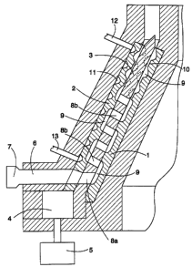
Figure 1 is a sectional side view of the apparatus of the invention.
The apparatus comprises an inner stator 1 and an outer stator 2 arranged
CA 02302661 2000-03-O1
WO 99/11374 PCT/FI98100676
3
outside it. At least the outer surface of the inner stator 1 and the inner
surface
of the outer stator 2 are conical. A conical rotor 3 is arranged between the
inner stator 1 and the outer stator 2. The rotor 3 is arranged to move
rotatably
between the inner stator 1 and the outer stator 2. The rotor is rotated with a
motor 5. The motor 5 can be a hydraulic motor or an electric motor,' for
example, or any other motor known per se suitable for the purpose. The motor
5 is arranged to rotate the rotor 3 by a gear system 4. By means of the gear
system 4, the speed of rotation of the rotor 3 can be adjusted as required.
But
the gear system 4 is not, however, necessary when using an electric motor, for
example, as the speed of rotation of the rotor 3 can be easily adjusted by
regulating the speed of rotation of the motor 5 in a manner known per se.
The apparatus is further provided with a supply conduit 6 along
which the material to be treated can be fed to the apparatus. The material to
be fed to the supply conduit 6 is supplied with a feeding device 7. The
feeding
device 7 can be a feed screw or a pump, for example, or any other device
known per se. The flow rate of the material to be supplied to the supply
conduit can be adjusted by means of the feeding device.
The material to be treated flows from the supply conduit 6 through a
feed opening 8a to the interior of the rotor 3. After this the material passes
in a
recess 9 in the inner stator 1 when the rotor 3 rotates outwards from the
apparatus, that is, upwards in Figure 1. From the recess 9 the material gains
access through an opening 8b outside the rotor and there in a recess in the
outer stator 2 further outwards from the apparatus. The recesses 9 are
arranged to end in such a manner that substantially all the material to be
. treated can be made to move through the openings 8b while a recess always
ends on the other side of the rotor 3. The edges of the openings 8a and 8b of
the rotor 3 are arranged to be sharp and similarly, the edges of the recesses
9
are arranged to be sharp in such a manner that when the material to be
treated moves through the openings 8a and 8b, the sharp edges of the
openings 8a and 8b and the recesses 9 cut and grind the material to be
treated at the boundary surtace of the rotor 3 and the stators 1 and 2 in such
a
manner that the material will be ground.
At the rear end of the apparatus, that is, at the end where the
material to be extruded is discharged from the apparatus, the recesses 9 are
arranged to continue as far as the outlet nozzle of the apparatus and the
recesses 9 are helical. In this part, flights 10 between the recesses 9 are
CA 02302661 2000-03-O1
WO 99/113?4 PGT/FI98/00676
4
arranged to be so low that such a large clearance remains between the flights
and the rotor 3 that some of the material to be treated can pass over the
flight 10 from one recess to another. In that case the material to be treated
will
be grated into a smaller form at the flight 10. If the material under
treatment is
5 rubber, for example, and a small amount of solvent oil is mixed into the
material, a rubber particle can be made to grate open at the flight 10. The
rear
end of the apparatus can also have helical recesses in the rotor 3, which is
illustrated in Figure 1 by means of broken lines. In the rotor 3 the recesses
are
in the opposite direction to those in the corresponding stators 1 and 2, that
is,
10 the helical recesses 9 are crossing, in which case the effect of the
recesses on
the material is considerable.
It is also possible to arrange to the apparatus cooling means, such
as a cooling channel 11 by means of which the apparatus and the material
treated there can be cooled so that it will retain its powdery form and not
get
stuck onto the inner surfaces of the apparatus. By supplying a cooling medium
to the cooling channel 11 through an inlet channel 12 situated close to the
rear
end of the apparatus and by conducting the cooling medium out along an
outlet channel 13 situated at the front end of the apparatus, the rear end of
the
apparatus can be cooled more efficiently and heat can be transferred from the
rear end of the apparatus towards the front end of the apparatus. Figure 1
shows cooling means arranged to the outer stator 2 but when required, cooling
means can also be arranged to the inner stator 1.
Figure 2 shows the rotor 3 of the apparatus as in Figure 1. The rotor
3 is rotated in the direction of arrow A. For the sake of clarity, Figure 2
shows
only some of the openings 8a and 8b of the rotor 3. The openings 8a and 8b
are naturally distributed evenly around the whole rotor 3. Figure 2 shows the
recesses 9 in the irrner stator 1 by a broken tine and the recesses 9 in the
outermost stator 2 are described by a line of dots and dashes. At the front
end
of the apparatus, the recesses 9 are discontinuous and oval and placed
obliquely. In that case, the recesses 9 move the material to be treated
outwards from the apparatus when the rotor 3 rotates, that is, upwards in
Figure 2, and force the material through the openings 8b when they end. At
the rear end of the apparatus, the recesses 9 continue as far as the outlet
point of the apparatus. For the sake of clarity, Figure 2 does not show the
recesses in the inner stator 1 at~the rear end of the apparatus. At this end,
the
flights between the recesses 9 are so low that some of the material can pass
CA 02302661 2000-03-O1
WO 99/11374 PCT/R198/00676
over the flights 10 from one recess to another, as illustrated by an-ows B. At
this point, the pitch angle of the recesses 9, that is, the angle with respect
to
the horizontal level is rather sharp, such as about 45°, in which case
the flow
over the flights 10 can be made reasonably great. The pitch angle cannot,
5 however, be too sharp in order that the recesses 9 will transport material
all
the time outwards and too high counterpressure will not be produced.
The apparatus can be easily constructed of separable parts placed
on top of one another, in which case it is easy to assemble and disassemble
and maintain the apparatus. Further, the stators 1 and 2 can be formed as in
Figure 1 of separate parts so that the surfaces which are against the rotor 3
and subject to wear can be changed separately.
Many different types of waste material, such as rubber, PEX,
leather or textile waste, can also be treated with the apparatus of the
invention. It is also possible to supply some polymer along with waste
material
1.5 into the apparatus. Then the apparatus is not cooled but it is possible to
make
an extrusion product containing waste material and polymer, such a tube, a
film or a cable sheath or other such product. If the waste material is PEX,
crosslinked PEX particles can be oriented at the rear end of the apparatus
when passing over the flights 10 as in this place the particles are close to
their
softening point.
The openings in the rotor 3 help to equalize the pressures of
different heights on different sides of the rotor 3, for which reason no heavy
constructions are required for mounting the apparatus in bearings and for
power transfer. By moving the rotor 3 in the axial direction, the clearances
befinreen the stators 1 and 2 and the rotor 3 can be adjusted easily and
simply
in the conical solution.
It is easy ~to adjust the amount to be supplied to the apparatus by
means of the feeding device 7. The feeding can be made in such a manner
that not an equal amount of material to be treated is fed as there is capacity
in
the apparatus for treatment, but so-called undersupply is used, in which case
the rate of feeding can be easily adjusted and an optimum loading situation
can be found for the apparatus. Undersupply can be realized also pulse-like to
the effect that a full amount of-the material to be treated is supplied
through
certain supply openings and some of the supply operiings are left partially or
totally empty so that the material to be treated is distributed substantially
evenly all over the apparatus. The speed of rotation of the rotor is also easy
to
CA 02302661 2000-03-O1
WO 99/11374 PCT/FI98/00676
6
adjust, in which case it is very easy to regulate the temperature of the
material
to be treated by adjusting the speed of rotation of the rotor and flow rate of
the
material to be supplied.
The drawings and the specification relating thereto are only meant
to illustrate the idea of the invention. In its details, the invention may
vary
within the scope of the claims. In that case, at the rear end of the
apparatus,
the recesses 9 can be arranged either to the stators or the rotor, or to both.
Further, there may be more than one rotor and more than two stators in the
apparatus.