Language selection

Search

Patent 2303042 Summary

Third-party information liability

Some of the information on this Web page has been provided by external sources. The Government of Canada is not responsible for the accuracy, reliability or currency of the information supplied by external sources. Users wishing to rely upon this information should consult directly with the source of the information. Content provided by external sources is not subject to official languages, privacy and accessibility requirements.

Claims and Abstract availability

Any discrepancies in the text and image of the Claims and Abstract are due to differing posting times. Text of the Claims and Abstract are posted:

  • At the time the application is open to public inspection;
  • At the time of issue of the patent (grant).
(12) Patent: (11) CA 2303042
(54) English Title: VEHICLE AIR SUSPENSION SYSTEM
(54) French Title: SYSTEME DE SUSPENSION PNEUMATIQUE POUR VEHICULE
Status: Expired
Bibliographic Data
(51) International Patent Classification (IPC):
  • B60G 7/02 (2006.01)
  • B60G 9/00 (2006.01)
  • B60G 11/28 (2006.01)
  • B60G 11/46 (2006.01)
(72) Inventors :
  • DEPUE, STEPHEN LINDSAY (Canada)
(73) Owners :
  • DEXTER TRAILER PRODUCTS OF CANADA CORPORATION (Canada)
(71) Applicants :
  • STANDEN'S LIMITED (Canada)
(74) Agent: MILLER THOMSON LLP
(74) Associate agent:
(45) Issued: 2004-04-13
(22) Filed Date: 2000-03-29
(41) Open to Public Inspection: 2000-10-09
Examination requested: 2000-03-29
Availability of licence: N/A
(25) Language of filing: English

Patent Cooperation Treaty (PCT): No

(30) Application Priority Data:
Application No. Country/Territory Date
09/288,707 United States of America 1999-04-09

Abstracts

English Abstract

A suspension assembly is provided for positioning a wheel support axle below the frame of a vehicle. The assembly comprises a support bracket extending downwardly from a vehicle frame, with a trailing arm pivotally mounted to said bracket and extending therefrom to the axle. The trailing arm is secured to the axle by means of a top, U-shaped clamping member mounted over the trailing arm and having side legs with recessed portions adapted to snuggly mate with the axle and a bottom plate adapted to fit snuggly within the U-shaped clamping member between the side legs and being located between the trailing arm and the U-shaped clamping bracket. A pin projects from a surface of the trailing arm and mates with a hole in the top, U-shaped clamping member or the bottom plate to hold the axle and trailing arm assembly against relative movement in a direction generally along the longitudinal axis of the trailing arm. welds secure the U-shaped clamping member sides legs to the bottom plate and welds securing the U-shaped clamping member side legs to the axle. An air spring is mounted between the axle and frame.


French Abstract

Un ensemble suspension est proposé pour positionner un essieu de support de roue au-dessous du châssis d'un véhicule. L'ensemble comprend un palier de support s'étendant vers le bas à partir d'un châssis de véhicule, avec un bras longitudinal monté de manière pivotante sur ledit palier et s'étendant à partir de celui-ci vers l'essieu. Le bras longitudinal est fixé à l'essieu au moyen d'un élément de serrage supérieur en forme de U monté sur le bras longitudinal et ayant des pattes latérales comportant des parties renfoncées conçues pour s'accoupler étroitement avec l'essieu et une plaque inférieure conçue pour s'adapter étroitement à l'intérieur de l'élément de serrage en forme de U entre les pattes latérales et étant situées entre le bras longitudinal et l'élément de serrage en forme de U. Une broche fait saillie à partir d'une surface du bras longitudinal et s'accouple à un trou dans l'élément de serrage supérieur en forme de U ou dans la plaque inférieure pour retenir l'ensemble essieu et bras longitudinal contre un déplacement relatif dans une direction généralement le long de l'axe longitudinal du bras longitudinal. Des soudures fixent les pattes latérales de l'élément de serrage en forme de U à la plaque inférieure et des soudures fixent les pattes latérales de l'élément de serrage en forme de U à l'essieu. Un ressort pneumatique est monté entre l'essieu et le châssis.

Claims

Note: Claims are shown in the official language in which they were submitted.


6

Claims:

1. A suspension assembly for positioning a wheel support axle
below the frame of a vehicle, said assembly comprising: a
support bracket extending downwardly from a vehicle frame, a
trailing arm pivotally mounted to said bracket and extending
therefrom to the axle and means for securing the trailing arm
to the axle comprising a top, U-shaped clamping member mounted
over the trailing arm and having side legs with recessed
portions adapted to snuggly mate with the axle, a bottom plate
adapted to fit snuggly within the U-shaped clamping member
between said side legs and being located between the trailing
arm and the U-shaped clamping bracket, at least one pin
projecting from a surface of the trailing arm and mating with
at least one hole in at least one of the top, U-shaped
clamping member and the bottom plate to hold the axle and
trailing arm assembly against relative movement in a direction
generally along the longitudinal axis of the trailing arm and
welds securing the U-shaped clamping member sides legs to the
bottom plate and welds securing the U-shaped clamping member
side legs to the axle.

2. A suspension assembly according to claim 1 wherein an
arcuate collar member is welded to the axle and the U-shaped
clamping member side legs are welded to said collar.

3. A suspension assembly according to claim 1 wherein an air
spring is mounted between the axle and the frame.

4. A suspension assembly according to clam 3 wherein a plate
is fixed on top of the U-shaped clamping member for engagement
with the air spring bottom.

5. A suspension assembly according to claim 4 wherein the air
spring is supported by a support plate fixed to the top
thereof, said support plate also supporting the trailing arm
bracket, said support plate being adapted for mounting under
the frame of a vehicle.


7


6. A suspension assembly according to claim 1 wherein the
trailing arm has a pin extending from the bottom thereof and
engaging a hole in said bottom plate.

7. A suspension assembly according to claim 1 wherein the
trailing arm has a pin extending from the top thereof and
engaging a hole in said U-shaped member.

8. A suspension assembly according to claim 1 wherein the
trailing arm has a pin extending from both the top and bottom
thereof to engage holes in both the U-shaped member and the
bottom plate.

9. A suspension assembly according to claim 1 wherein the
welds between the U-shaped clamping member side legs and the
bottom plate do not contact the trailing arm being held
between the U-shaped clamping member and the bottom plate.


Description

Note: Descriptions are shown in the official language in which they were submitted.


CA 02303042 2000-03-29
1
Vehicle Air Suspension System
Background of the Invention
This invention relates to a vehicle air spring axle
suspension system and, more particularly, to new and improved
means for connecting an axle housing to a trailing arm.
Almost every type of vehicle has incorporated into its
design a suspension system. The purpose of this suspension
system is to reduce the level of transmitted load, shock and
vibrations realized by the contents or passengers of the
vehicle when it encounters rough terrain during its movement.
Among such systems are coil springs, leaf springs, and
pneumatic systems which employ the so called "air spring".
The air spring basic components consist of an axle system
(including tires and such), an air spring (loosely a sealed
rubber bag) and its associated hardware, an air link beam or
trailing arm pivotally connecting the axle to the vehicle
frame and all of the nuts and bolts, brackets etc. that hold
all of the pieces together.
The air spring market is highly competitive with the
result that all manufacturers are looking for ways of reducing
both weight and cost of the air suspension system. Thus,
designers of air suspension systems have already gone through
the exercise of minimizing the size of virtually every
component while maintaining an acceptable safety factor.
One typical air suspension system is shown in Schwartz,
U.S. Patent 4,162,090, issued July 24, 1997. This shows a
vehicle axle suspension assembly that includes a locator plate
that is welded to the axle housing and also heat shrunk onto
the trailing arm. However, this arrangement still requires U-
bolts that extend around the axle for securely clamping the
axle to the trailing arm.
Another form of connection between a trailing arm and
axle is shown in Carlson et al., U.S. Patent 3,630,541, issued
December 28, 1971. In this design the trailing arm has axle
stop members to prevent relative movement between the trailing

CA 02303042 2000-03-29
2
arm and the axle. However, once again U-bolts are used for
securely clamping the axle to the trailing arm.
It is an object of the present invention to provide a
suspension assembly which is lighter and requires even fewer
components than those described in the prior art.
Summary of the Invention
The present invention in its broadest aspect relates to a
suspension assembly for positioning a wheel support axle below
the frame of a vehicle. This assembly includes a support
bracket extending downwardly from the vehicle frame, a
trailing arm pivotally mounted to this bracket and extending
to an axle and means for securing the trailing arm to the
axle.
This means for securing the trailing arm to the axle
includes a top, U-shaped clamping member mounted over the
trailing arm and having side legs with recessed portions
adapted to snuggly mate with the axle. A bottom plate is
adapted to fit snuggly within the U-shaped clamping member
between the side legs and is located between the trailing arm
and the U-shaped clamping bracket. At least one pin projects
from a surface of the trailing arm and mates with at least one
hole in at least one of the top, U-shaped clamping member and
the bottom plate to hold the axle and trailing arm assembly
against relative movement in a direction generally along the
longitudinal axis of the trailing arm. This assembly is then
completed by weld beads extending along the connector edge
between the U-shaped clamping member side legs and the bottom
plate and weld beads securing the U-shaped clamping member
side legs to the axle.
Description of the Preferred Embodiments
Preferably an arcuate collar member is first welded to
the axle and then the U-shaped clamping member side legs are
welded to this collar. Pins may extend from either the top or
bottom face of the trailing arm or either the top or bottom

CA 02303042 2000-03-29
3
face. These pins mate with holes extending into the U-shaped
clamping member or the bottom plate or into both of these.
According to a preferred embodiment, the assembly of the
invention includes a top plate which is secured to the bottom
of an axle frame. Both the bracket which supports the
trailing arm and the air spring itself are secured to this top
plate. It is also preferable to include an additional plate
which is fixed to the top of the U-shaped clamping member to
provide a firm bottom support for the air spring.
It has been found that the assembly of this invention
with its welded joints is less prone to becoming loose and
causing failure than is a traditional U-bolt assembly. Also,
eliminating the U-bolts and associated hardware reduces weight
and allows for a simpler system and easier installation. The
assembly of this invention can be pre-mounted on an axle
assembly and this complete axle and air spring sub-assembly
can then be mounted as a single unit onto the frame of a
trailer or other vehicle.
Brief Description of the Drawings
The foregoing and other important objects and desirable
features inherent in an encompassed by the invention, together
with many of the purposes and uses thereof, will become
readily apparent from the reading of the ensuing description
in conjunction with the next drawings, in which:
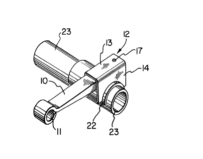
Fig. 1 is a perspective view of a trailing arm assembly
according to the invention;
Fig. 2 is an exploded view of the parts of Fig. 1;
Fig. 3 is an elevation view of the assembly of Fig. 1;
Fig. 4 is a side elevation of the assembly of Fig. 1
mounted on a vehicle frame;
Fig. 5 is a perspective view of the assembly of Fig. 1
mounted on a frame; and
Fig. 6 is a perspective view of an alternative form of
trailing arm assembly according to the invention.
The basic part of the assembly is shown in Figs. 1 to 3.
This shows a trailing arm 10 with a pivotal connector end 11.

CA 02303042 2000-03-29
4
The trailing arm 10 is connected to an axle tube 23 preferably
using an intermediate arcuate collar 22. This collar 22 is
first welded to the axle tube 23 by way of an edge weld bead
24.
A U-shaped bracket 12 is placed over the trailing arm 10,
this bracket having a top bridge portion 13 and downwardly
extending side legs 14. The side legs include arcuate
recesses 15 which are designed to snuggly mate either directly
with the axle tube 23 or with the collar 22 fixed over the
axle tube. A bottom plate 20 is placed below the trailing arm
10 such that the trailing arm is snuggly sandwiched between
the U-shaped bracket bridge portion 13 and the plate 20 as
illustrated in Fig. 3. Pin 16 extending upwardly from the top
face of trailing arm 10 mates with a hole 17 in the bridge
portion 13 of the U-shaped bracket 12 and the trailing arm 10
may also include a downwardly directed pin 18 for mating with
the hole 21 in the bottom plate 20. These are designed to
hold the axle and trailing arm assembly against any relative
movement in a direction generally along the longitudinal axis
of the trailing arm 10. The bottom plate 20 is rigidly fixed
to the side legs 14 by way of weld beads 32 extending along
the corners between the bottom of the bottom plate 20 and the
inside faces of the side legs 14. It is important that those
welds 32 do not contact any part of the trailing arm within
the U-shaped bracket 12. The trailing arm 10 is made of heat-
treated spring steel and welds on this material tend to crack,
resulting in failure of such a connection. This problem is
avoided according to the present invention by the assembly
using the bracket 12, plate 20 and pin 16, with welds only
between the plate 20 and bracket 12.
Finally, the edges formed between the arcuate recess 15
of the side legs 14 and the arcuate collar 22 or the axle tube
itself are welded together by means of the welding bead 25.
A complete assembly is shown in Figs. 4 and 5 including a
bracket 27 with a pivot 26 for connecting to trailing arm 10.
The bracket 27 is fixed to a support plate 28 which is in turn
mounted below the frame 30 of a vehicle. Also mounted on top

CA 02303042 2000-03-29
of the U-shaped bracket 12 is a support plate 28 for
supporting the bottom of an air spring 31. The air spring is
also connected to the top support plate 28.
This complete assembly as shown in Figs. 4 and 5,
5 including axle 23, may comprise a prefabricated sub-assembly
sold as an assembled unit. This sub-assembly is then quickly
and easily connected to a frame 30 by means of bolts 35.
Fig. 6 shows an alternative form of trailing arm 40
connected to an alternative square form of axle tube 42. For
this design, the shape of the U-shaped bracket 41 is modified
to snuggly fit around the square axle tube 42. The outer end
of arm 40 has an offset portion 43 above which the air spring
may be mounted.
Although the invention has been herein shown and
described in what is conceived to be the most practical and
preferred embodiment, it is recognized that departures may be
made therefrom within the scope of the invention, which is not
to be limited to the illustrative details disclosed.

Representative Drawing
A single figure which represents the drawing illustrating the invention.
Administrative Status

For a clearer understanding of the status of the application/patent presented on this page, the site Disclaimer , as well as the definitions for Patent , Administrative Status , Maintenance Fee  and Payment History  should be consulted.

Administrative Status

Title Date
Forecasted Issue Date 2004-04-13
(22) Filed 2000-03-29
Examination Requested 2000-03-29
(41) Open to Public Inspection 2000-10-09
(45) Issued 2004-04-13
Expired 2020-03-29

Abandonment History

There is no abandonment history.

Payment History

Fee Type Anniversary Year Due Date Amount Paid Paid Date
Request for Examination $400.00 2000-03-29
Registration of a document - section 124 $100.00 2000-03-29
Application Fee $300.00 2000-03-29
Maintenance Fee - Application - New Act 2 2002-04-02 $100.00 2002-03-28
Maintenance Fee - Application - New Act 3 2003-03-31 $100.00 2003-02-26
Maintenance Fee - Application - New Act 4 2004-03-29 $100.00 2004-01-19
Final Fee $300.00 2004-01-22
Maintenance Fee - Patent - New Act 5 2005-03-29 $200.00 2005-01-27
Maintenance Fee - Patent - New Act 6 2006-03-29 $200.00 2006-03-29
Maintenance Fee - Patent - New Act 7 2007-03-29 $200.00 2007-02-01
Maintenance Fee - Patent - New Act 8 2008-03-31 $200.00 2008-01-29
Maintenance Fee - Patent - New Act 9 2009-03-30 $200.00 2009-03-30
Maintenance Fee - Patent - New Act 10 2010-03-29 $250.00 2010-03-29
Maintenance Fee - Patent - New Act 11 2011-03-29 $250.00 2011-03-29
Maintenance Fee - Patent - New Act 12 2012-03-29 $250.00 2012-03-28
Maintenance Fee - Patent - New Act 13 2013-04-02 $250.00 2013-03-27
Registration of a document - section 124 $100.00 2014-02-05
Maintenance Fee - Patent - New Act 14 2014-03-31 $250.00 2014-03-28
Maintenance Fee - Patent - New Act 15 2015-03-30 $450.00 2015-03-30
Maintenance Fee - Patent - New Act 16 2016-03-29 $450.00 2016-03-01
Maintenance Fee - Patent - New Act 17 2017-03-29 $450.00 2017-03-16
Maintenance Fee - Patent - New Act 18 2018-03-29 $450.00 2018-03-26
Registration of a document - section 124 $100.00 2019-03-07
Maintenance Fee - Patent - New Act 19 2019-03-29 $450.00 2019-03-14
Registration of a document - section 124 2022-01-19 $100.00 2022-01-19
Owners on Record

Note: Records showing the ownership history in alphabetical order.

Current Owners on Record
DEXTER TRAILER PRODUCTS OF CANADA CORPORATION
Past Owners on Record
DEPUE, STEPHEN LINDSAY
IMT STANDEN'S LIMITED PARTNERSHIP
STANDEN'S LIMITED
Past Owners that do not appear in the "Owners on Record" listing will appear in other documentation within the application.
Documents

To view selected files, please enter reCAPTCHA code :


To view images, click a link in the Document Description column. To download the documents, select one or more checkboxes in the first column and then click the "Download Selected in PDF format (Zip Archive)" or the "Download Selected as Single PDF" button.

List of published and non-published patent-specific documents on the CPD .

If you have any difficulty accessing content, you can call the Client Service Centre at 1-866-997-1936 or send them an e-mail at CIPO Client Service Centre.


Document
Description 
Date
(yyyy-mm-dd) 
Number of pages   Size of Image (KB) 
Representative Drawing 2000-10-02 1 9
Abstract 2000-03-29 1 32
Description 2000-03-29 5 236
Claims 2000-03-29 2 71
Drawings 2000-03-29 2 68
Cover Page 2000-10-02 1 43
Cover Page 2004-03-11 1 46
Correspondence 2004-01-22 1 29
Assignment 2000-03-29 6 238
Maintenance Fee Payment 2019-03-14 1 33
Returned mail 2019-08-06 2 102
Assignment 2014-02-05 5 111
Fees 2014-03-28 2 57
Correspondence 2014-08-29 4 117
Correspondence 2014-09-15 1 22
Correspondence 2014-09-15 1 29
Fees 2015-03-30 1 33
Fees 2016-03-01 1 33