Note: Descriptions are shown in the official language in which they were submitted.
CA 02303159 2000-03-09
WO 99/13924 PCT/US98/19627
POLYETHER BLOCK AMIDE CATHETER BALLOONS
BACKGROUND OF THE INVENTION
This invention generally relates to intravascular catheters, such as balloon
dilatation catheters used in percutaneous transluminal coronary angioplasty
(PTCA).
PTCA is a widely used procedure for the treatment of coronary heart disease.
In this, procedure, a balloon dilatation catheter is advanced into the
patient's
coronary artery and the balloon on the catheter is inflated within the
stenotic region
of the patient's artery to open up the arterial passageway and thereby
increase the
blood flow there through. To facilitate the advancement of the dilatation
catheter
into the patient's coronary artery, a guiding catheter having a preshaped
distal tip is
first percutaneously introduced into the cardiovascular system of a patient by
the
Seldinger technique through the brachial or femoral arteries. The catheter is
advanced until the preshaped distal tip of the guiding catheter is disposed
within the
aorta adjacent the ostium of the desired coronary artery, and the distal tip
of the
guiding catheter is then maneuvered into the ostium. A balloon dilatation
catheter
may then be advanced through the guiding catheter into the patient's coronary
artery
until the balloon on the catheter is disposed within the stenotic region of
the patient's
artery. The balloon is inflated to open up the arterial passageway and
increase the
blood flow through the artery. Generally, the inflated diameter of the balloon
is
approximately the same diameter as the native diameter of the body lumen being
dilated so as to complete the dilatation but not over expand the artery wall.
After the
balloon is finally deflated, blood flow resumes through the dilated artery and
the
dilatation catheter can be removed therefrom.
To reduce the restenosis rate and to strengthen the dilated area, physicians
frequently implant an intravascular prosthesis, generally called a stent,
inside the
artery at the site of the lesion. Stents may also be used to repair vessels
having an
intimal flap or dissection or to generally strengthen a weakened~sectiori of a
vessel.
Stents are usually delivered to a desired location within a coronary artery in
a
contracted condition on a balloon of a catheter which is similar in many
respects to a
balloon angioplasty catheter, and expanded to a larger diameter by expansion
of the
balloon. The balloon is deflated to remove the catheter and the stent left in
place
CA 02303159 2000-03-09
WO 99/13924 PC'T/US98/19627
2
within the artery at the site of the dilated lesion. See for example, U.S.
Pat. No.
5,507;768 (Lau et al.) and U.S. Pat. No. 5,458,615 (Klemm et al.), which are
incorporated herein by reference.
One type of catheter frequently used in PTCA procedures is an over-the-wire
type balloon dilatation catheter. When using an over-the wire dilatation
catheter, a
guidewire is usually inserted into an inner lumen of the dilatation catheter
before it is
introduced into the patient's vascular system and then both are introduced
into and
advanced through the guiding catheter to its distal tip which is seated within
the
ostium. The guidewire is first advanced out the seated distal tip of the
guiding
catheter into the desired coronary artery until the distal end of the
guidewire extends
beyond the lesion to be dilatated. The dilatation catheter is then advanced
out of the
distal tip of the guiding catheter into the patient's coronary artery, over
the previously
advanced guidewire, until the balloon on the distal extremity of the
dilatation catheter
is properly positioned across the lesion to be dilatated. Once properly
positioned
across the stenosis, the balloon is inflated one or more times to a
predetermined
size with radiopaque liquid at relatively high pressures (e.g., generally 4-12
atmospheres) to dilate the stenosed region of a diseased artery. After the
inflations,
the balloon is finally deflated so that the dilatation catheter can be removed
from the
dilated stenosis to resume blood flow.
Another type of dilatation catheter, the rapid exchange type catheter, was
introduced by ACS under the trademark ACS RX~ Coronary Dilatation Catheter. It
is described and claimed in U.S: Patent 5,040,548 (Pock), U.S. Patent
5,061,273
(Pock), and U.S. Patent 4,748,982 (Horzewski et al.) which are incorporated
herein
by reference. This dilatation catheter has a short guidewire receiving sleeve
or inner
lumen extending through a distal portion of the catheter. The sleeve or inner
lumen
extends proximally from a frst guidewire port in the distal end of the
catheter to a
second guidewire port in the catheter spaced proxiri~ally from the inflatable
member
of the catheter. A slit may be provided in the wall of the catheter body which
extends distally from the second guidewire port, preferably to a location
proximal to
the proximal end of the inflatable balloon. The structure of the catheter
allows for
the rapid exchange of the catheter without the need for an exchange wire or
adding
a guidewire extension to the proximal end of the guidewire.
CA 02303159 2000-03-09
WO 99/13924 PCTNS98/19627
3
The perfusion type dilatation catheter is another type of dilatation catheter.
This catheter, which can take the form of an over-the-wire catheter or a rapid
exchange type catheter, has one or more perfusion ports proximal to the
dilatation
balloon in fluid communication with an guidewire receiving inner lumen
extending to
the distal end of the catheter. One or more perfusion ports are preferably
provided
in the catheter distal to the balloon which are also in fluid communication
with the
inner lumen extending to the distal end of the catheter. This provides
oxygenated
blood downstream from the inflated balloon to thereby prevent or minimize
ischemic
conditions in tissue distal to the catheter. The perfusion of blood distal to
the inflated
balloon allows for long term dilatations, e.g. 30 minutes or even several
hours or
more.
The balloons for prior dilatation catheters utilized in angioplasty procedures
generally have been formed of relatively inelastic polymeric materials such as
polyvinyl chloride, polyethylene, polyethylene terephthalate (PET),
polyolefinic
ionomers, and nylon. An advantage of such inelastic materials when used in
catheter balloons is that the tensile strength, and therefore the mean rupture
pressure, of the balloon is high. Catheter balloons must have high tensile
strength
in order to exert sufficient pressure on the stenosed vessel and effectively
open the
patient's passageway. Consequently the high strength balloon can be inflated
to
high pressures without a risk that the balloon will burst during
pressurization.
Similarly, the wall thickness of high strength balloons can be made thin, in
order to
decrease the catheter profile, without a risk of bursting.
Those inelastic materials having the least elasticity are also classified as
"non-compliant" and "semi-compliant" materials, and include PET and nylon.
Such
non-compliant material exhibits little expansion in response to increasing
levels of
inflation pressure. Because the non-compliant material has a limited ability
to
expand, the uninflated balloon must be made sufficiently large that, when
inflated,
the balloon has sufficient working diameter to compress the stenosis and open
the
patient's passageway. However, a large profile non-compliant balloon can make
the
catheter difficult to advance through the patient's narrow vasculature
because, in a
uninflated condition, such balloons form flat or pancake shape wings which
extend
radially outward. Therefore, some compliance is desirable in an angioplasty
CA 02303159 2000-03-09
WO 99/13924 PCT/US98/19627
4
catheter balloon. Additionally., balloons formed of material with high
compliance
have increased softness, which improves the ability of the catheter to track
the
tortuous vasculature of the patient and cross the stenosis, to effectively
position the
balloon at the stenosis. The softness of a balloon is expressed in terms of
the
balloon modulus, where a relatively soft balloon has a relatively low flexural
modulus
of less than about 150,000 psi (1034 MPa).
Therefore', what has been needed is a relatively soft catheter balloon having
a
high rupture pressure. The present invention satisfies these arid other needs.
SUMMARY OF THE INVENTION
The invention is directed to an inflatable member such as a balloon which is
formed at least in part of a polyamidelpolyether block copolymer thermoplastic
elastomer, commonly referred to as polyether block amide (PEBA). The balloon
of
the invention exhibits high tensile strength, high elongation, and low
flexural
modulus.
A balloon catheter of the invention generally comprises a catheter having an
elongated shaft with an inflatable balloon formed of PEBA thermoplastic
elastorner
on a distal portion of the catheter. Suitable PEBA balloon materials include,
but are
not limited to, PEBAX~, a pofyamide/polyether polyester available from Atochem
and described in U.S. Patents 4,331,786 and 4,332;920 (Foy et al.), which are
incorporated herein by reference. The presently preferred PEBA copolymer is
polyamide/polyether polyester copolymer.
The presently preferred balloon is formed from 100% PEBA. However, the
balloon can be formed of a blend of PEBA with one or more different polymeric
materials. Suitable polymeric materials for blending with PEBA include those
polymers listed above used to make balloons for prior dilatation catheters,
such as
nylon. In a presently preferred embodiment, the balloon is a single polymeric
layer.
However, the balloon may also be multilayered, where the balloon is formed by
coextruding two or more layers with one or more layers formed at least in part
of
PEBA.
Various designs for balloon catheters well known in the art may be used in
the catheter of the invention having a balloon formed at least in part PEBA.
For
CA 02303159 2000-03-09
WO 99/13924 PCT/US98/19627
example, the catheter may be a conventional over-the-wire dilatation catheter
for
angiopiasty having a guidewire receiving lumen extending the length of the
catheter
shaft from a guidewire port in the proximal end of the shaft, or a rapid
exchange
dilatation catheter having a short guidewire lumen extending to the distal end
of the
5 shaft from a guidewire port located distal to the proximal end of the shaft.
Additionally, the catheter may be used to deliver a stent mounted on the
catheter
balloon.
The balloon of the invention formed of PEBA thermoplastic elastomer,
combines improved softness and tensile strength, to provide low profile
balloon
~ catheters having excellent ability to tract the patient's vasculature, cross
the
stenosis, and compress the stenosis to open the patient's vessel. These and
other
advantages of the invention will become more apparent from the following
detailed
description of the invention and the accompanying exemplary drawings.
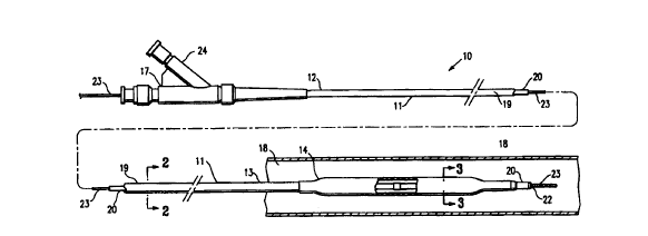
BRIEF DESCRIPTION OF THE DRAWINGS
Fig. 1 is an elevational. view partially in section of the catheter of the
invention
showing the balloon in an unexpended state.
Fig. 2 is a transverse cross sectional view of the catheter of Fig. 1 taken
along
lines 2-2.
Fig. 3 is a transverse cross sectional view of the catheter of Fig. 1 taken
along
lines 3-3.
Fig. 4 is an elevational view partially in section of the catheter of the
invention.
Fig. 5 is a transverse cross sectional view of the catheter of Fig. 4 taken
along
lines 5-5.
CA 02303159 2000-03-09
WO 99/13924 PCT/US98/19627
6
DETAILED DESCRIPTION OP THE INVENTION
As shown in Fig. 1, the catheter 10 of the invention generally includes a an
elongated catheter shaft 11 having a proximal section 12 and distal section
13, an
inflatable balloon 14 formed at least in part of PEBA on the distal section 13
of the
catheter shaft 11, and an adapter 17 mounted on the proximal section 12 of
shaft 11
to direct inflation fluid to the interior of the inflatable balloon. Figs. 2
and 3 illustrate
transverse cross sections of the catheter shown in Fig. 1, taken along lines 2-
2 and
3-3 respectively.
In the embodiment illustrated in Fig. 1, the intravascular catheter 10 of the
invention is an over-the-wire catheter, and is illustrated within a patient's
body lumen
18 with the balloon 14 in an unexpanded state. The catheter shaft 11 has an
outer
tubular member 19 and an inner tubular member 20 disposed within the outer
tubular member and defining, with the outer tubular member, inflation lumen
21.
Inflation lumen 21 is in fluid communication with the interior chamber 15 of
the
inflatable balloon 14. The inner tubular member 20 has an inner lumen 22
extending
therein, which is configured to slidably receive a guidewire 23 suitable for
advancement through a patient's coronary arteries. The distal extremity of the
inflatable balloon 14 is sealingly secured to the distal extremity of the
inner tubular
member 20 and the proximal extremity of the balloon is seafingly secured to
the
distal extremity of the outer tubular member 19.
The balloons of the invention are formed at least in part of
polyamide/polyether block (PEBA) copolymers. The presently preferred PEBA
copolymers have polyamide and polyether segments linked through ester
linkages,
i.e. polyamidelpolyether polyesters. However, other linkages, such as amide
linkages, can also be used. Polyamide/polyether polyester block copolymers are
made by a molten state polycondensation reaction of a dicarboxylic polyamide
and a
polyether diol. The result is a short chain polyester made up of blocks of
polyamide
and polyether. The -polyamide and polyether blocks are not miscible. Thus, the
materials are characterized by a two phase structure having a thermoplastic
region
that is primarily polyamide and an elastomer region that is rich in polyether.
The
polyamide segments are semicrystalline at room temperature. The generalized
CA 02303159 2000-03-09
WO 99/13924 PCT/US98/19627
7
chemical formula for these polyamide/polyether polyester block copolymers may
be
represented. by the following formula:
HO-(C-PA-C-O-PE-O)~ H
O O
in which PA is a polyamide hard segment, PE is a polyether soft segment, and
the
repeating number n is between 5 and 10. The polyamide hard segment is a
polyamide of C6 or higher, preferably C~a-C~2, carboxylic acids; C6 or higher,
preferably Coo-C~2, organic diamines; or Cs or higher, preferably Coo-C12,
aliphatic cu-
amino-a-acids. The percentage by weight of the block copolymer attributable to
the
polyamide hard segments is between about 50% to about 95%. The polyether soft
segment is a polyether of C2-Coo diols, preferably C4-C6 diols. The block
copolymer
has a flexural modulus of less than about 150,000 psi (1034 MPa), preferably
less
than 120,000 psi (827 MPa).
The polyamide segments are suitably aliphatic polyamides, such as nylons
12, 11, 9, 6, 6/12, 6/11, 6/9, or 6/fi. Most preferably they are nylon 12
segments.
The polyamide segments may also be based on aromatic polyamides but in such
case signficantly lower compliance characteristics are to be expected. The
polyamide segments are relatively low molecular weight, generally within the
range
of 500-8,000, more preferably 2,000-6,000, most preferably about 3,000-5,000.
Another range which is of interest is 300-15,000.
The polyether segments are aliphatic polyethers having at least 2 and no
more than 10 linear saturated aliphatic carbon atoms between ether linkages.
More
preferably the ether segments have 4-6 carbons between ether linkages, and
most
preferably they are poly(tetramethylene ether) segments. Examples of other
polyethers which may be employed in place of the preferred tetramethylene
ether
segments include polyethylene glycol, polypropylene glycol,
poly(pentamethylene
ether) and poly(hexamethylene ether). The hydrocarbon portions of the
polyether
may be optionally branched. An example is the polyether of 2-ethylhexane diol.
Generally such branches will contain no more than two carbon atoms. The
molecular weight of the polyether segments is suitably between about 400 and
CA 02303159 2000-03-09
WO 99/13924 PGTNS98/19627
8
2,500, preferably between 650 and 1,000. Another range which is of interest is
200-
6, 000.
The weight ratio of polyamide to polyether in the polyamide/polyether
polyesters used in the invention desirably should be in the range of 50/50 to
95/5,
preferably between 60/30 and 92/08, more preferably, between 70/30 and 90/10.
Polyamide/polyether polyesters are sold commercially under the PEBAX
trademark by Atochem North America, Inc., Philadelphia, PA. A suitable polymer
grade for the intravascular balloon catheter of the invention is the PEBAX~ 33
series. In the embodiment in which the balloon is 100% PEBA or a blend of PEBA
and a polyamide, preferably PEBA and nylon, the presently preferred PEBAX~
polymers have a hardness of Shore D durometer of at least about 60D,
preferably
between about 60D to about 72D, i.e. PEBAX~ 6033 and 7233. In the embodiment
in which the baboon is a coextruded multilayered balloon, with at least one
layer
formed of PEBA, the presently preferred PEBAX~ polymers have a hardness of
Shore D durometer of at least about 35 D, preferably between about 35D to
about
72D, i.e. PEBAX~ 3533 and 7233.
The PEBAX~ 7033 and 6333 polymers are made up of nylon 12 segments
and polytetramethylene ether segments in about 90/10 and about 80/20 weight
ratios, respectively. The average molecular weight of the individual segments
of
nylon 12 is in the range of about 3,000-5,000 grams/mole and of the
polytetramethylene ether segments are in ranges of about 750-1,250 for the
6333
polymer and about 500-800 for the 7033 polymer. The intrinsic viscosities of
these
polymers are in the range of 1.33 to 1.50 dllg. Generally speaking, balloons
of
PEBAX~ 7033 type polymer exhibit borderline non-compliant to semi-compliant
, behavior and balloons of Pebax~ 6333 type polymer show semi-compliant to
compliant distention behavior, depending on the balloon forming conditions.
While the PEBAX~-type polyamide/polyether polyesters are most preferred, it
is also possible to use other PEBA polymers with the physical properties
specified
herein and obtain similar compliance, strength and softness characteristics in
the
finished balloon.
The presently preferred PEBA material has an elongation at failure at room
temperature of at least about 150%, preferably about 300% or higher, and an
CA 02303159 2000-03-09
WO 99/13924 PCT/US98/19627
9
ultimate tensile strength of at least 8,000 psi. The balloon has sufficient
strength to
withstand the inflation pressures needed to inflate the balloon and compress a
stenosis in a patient's vessel. The burst pressure of the balloon is at least
about 10
ATM, and is typically about 1 fi-21 ATM. The wall strength of the balloon is
at least
about 15,000 psi (103 MPa), and typicaily from about 25,000 psi (172 Mpa) to
about
35,000 psi (241 MPa}.
As best illustrated in Fig. 3, the inflatable balloon 14 shown in Fig. 1 is
formed
of a single layer of polymeric material. The balloon may be 100% PEBA or a
PEBA/polymer blend. The presently preferred polymer blend is a PEBAX~/nylon
blend, and the preferred weight percent of nylon is from about 30% to about
95% of
the total weight. The inflatable balloon 14 may also have multiple layers
formed
from coextruded tubing, in which one or more layers is at least in part formed
from
PEBA. In a presently preferred embodiment, the multilayered balloon is made
from
coextruded tubing have at least a nylon layer and a PEBA layer. The presently
preferred PEBA is PEBAX~, and the presently preferred nylon is nylon 11, nylon
12,
or blends thereof. The PEBAX~ may be the inner layer or the outer layer of the
balloon.
The balloon of the invention can be produced by conventional techniques for
producing catheter inflatable members, such as blow molding, and may be
preformed by stretching a straight tube before the balloon is blown. The
balloons
may be formed by expansion of tubing, as for example at a hoop ratio of
between 3
and 8. The presently preferred PEBA .balloon material is not crosslinked. The
bonding of the balloon to the catheter may be by conventional techniques, such
as
adhesives and fusion with compatibilizers.
~ Fig. 2, showing a transverse cross section of the catheter shaft 11,
illustrates
the guidewire receiving lumen 22 and inflation lumen 21. The balloon 14 can be
inflated by radiopaque fluid from an inflation port 24, from inflation lumen
21
contained in the catheter shaft 11, or by other means, such as from a
passageway
fom~ed between the outside of the catheter shaft and the member forming the
balloon, depending on the particular design of the catheter. The details . and
mechanics of balloon inflation vary according to the specific design of the
catheter,
and are well known in the art.
CA 02303159 2000-03-09
WO 99/13924 PCT/US98/19627
The length of the balloon 14 may be about 0.5 cm to about 6 cm, preferably
about 1.0 cm to about 4.0 cm. After being formed, the balloon working length
outer
diameter at nominal pressure (e.g. 6-8 ATM) is generally about 0.15 cm to
about 0.4
cm, and typically about 0.3 cm, although balloons having an outer diameter of
about
5 1 cm may also be used. The single wall thickness is about 0.0004 inches (in)
(0.0102 mm) to about 0.0015 in (0.0381 mm), and typically about .0006 in
(0.0152
mm). In the embodiment in which the coextrusion balloon has two layers, the
nylon
layer single wall thickness is about .0003 in (0.0076 mm) to about .0006 in
(0.0152
mm), and the PEBAX layer is about .0002 in (0.0051 mm) to about .0005 in
(0.0127
10 mm).
Another embodiment of the invention is shown in Fig. 4, in which a stent 16 is
disposed about the balloon 14 for delivery within patient's vessel. Fig. 5
illustrates a
transverse cross section of the catheter shown in Fig. 4, taken along line 5-
5. The
stent 16 may be any of a variety of stem materials and forms designed to be
implanted by an expanding member, see for example U.S. Patent 5,514,154 (Lau
et
al.) and 5,443,500 (Sigwart), incorporated by reference. For example, the
stent
material may be stainless steel, a NiTi alloy, a plastic material, or various
other
materials. The stent is shown in an unexpended state in Fig. 4. The stent has
a
smaller diameter for insertion and advancement into the patient's lumen, and
is
expandable to a larger diameter for implanting in the patient's lumen. The
balloon of
the in~rention formed at least in part of PEBA has improved abrasion
resistance,
useful in stent delivery, due to the PEBA. In the embodiment of the invention
in
which the balloon has at least two coextruded layers, a balloon used for stent
delivery preferably has the PEBA layer as the outer layer, to provide improved
resistance to puncture by the stent. Additionally, the stent retention force
is
improved when the balloon is formed by coextrusion.
The following examples more specifically illustrate the invention.
EXAMPLE 1
PEBAX~ 7033 was extruded into tubular stock having 0.035 in (0.889 mm)
outer diameter (OD) and 0.019 in (0.483 mm) inner diameter (ID). The tubing
was
necked on one side at room temperature to ID of 0.018 in (0.457 mm). The
tubing
CA 02303159 2000-03-09
WO 99/13924 PCT/US98/19627
19
was then made into 20 balloons using a glass mold at a temperature of 242
°F
(116.7 °C) inside the mold and a blow pressure of 340 psi (2343 kPa).
The balloons
had an OD of 3 mm and a length of 20 mm. The balloon working length had a wall
thickness of 0.0006 in (0.0152 mm) to 0.0007 in (0.0178 mm). The mean rupture
pressure of the balloons was found to be 310 psi (2136 kPa) with a standard
deviation of 17.21 psi (119 kPa).
EXAMPLE 2
PEBAX~ 6033 and nylon 12 was coextruded into two layered tubing, with
PEBAX~ as the outer layer and nylon as the inner layer. The tubing had a 0.035
in
(0.889 mm) OD and a 0.0195 in (0.495 mm) ID, and a nylon layer thickness of
0.004
in (0.102 mm) and a PEBAX~ layer thickness of 0.002. (0.051 mm). The tubing
was
then made into 20 balloons using a glass mold as in Example 1, at a
temperature of
235.5 °F (113 °C) inside the mold and a blow pressure of 300 psi
(2067 kPa). The
balloon working length had a wall thickness of 0.0005 in (0.0127 mm) to
0.00065 in
(0.0165 mm). The mean rupture pressure of the balloons was found to be 317 psi
(2184 kPa) with a standard deviation of 23.3 psi (161 kPa).
EXAMPLE 3
Twenty percent PEBAX~ 7233 and 80% nylon 12 was blended in a single
screw extruder, and extruded into tubular stock having 0.0325 in (0.826 mm) OD
and 0.015 in (0.381 mm) ID. The tubing was then made into 10 balloons using a
glass mold as in Example 1, at a temperature of 320 °F (160 °C)
inside the mold and
a blow pressure of 225 psi (1550 kPa). The balloon working length had a wall
thickness of 0.00045 in (0.0114 mm). The mean rupture pressure of the balloons
was found to be 280 psi (1929 kPa).
it will be apparent from the foregoing that, while particular forms of the
invention have been illustrated and described, various modifications can be
made
without departing from the spirit and scope of the invention. For example,
while the
CA 02303159 2000-03-09
WO 99/13924 PCT/US98/1962~
12
balloon catheter illustrated in . Fig. 1 has inner and outer tubular members
with
independent lumens, a single tubular membered shaft having two lumens therein
may also be used. Other modifications may be made without departing from the
scope of the invention.