Note: Descriptions are shown in the official language in which they were submitted.
CA 02303340 2000-03-08
WO 99/15422 PCT/US9$/19594
-1-
CLOSURE SYSTEM FOR CONTAINERS
Field Of The Invention
The present invention relates, in general, to closure systems for molded
plastic containers. In particular, the present invention relates to closure
systems for
molded plastic containers containing sterile fluids and having a cap
associated therewith.
l~aclcground Of The Invention
Various food, medical and household products are presently packaged in
molded plastic containers. Most of these containers include a dispensing port,
and a
closure system which creates a barrier for containing and/or protecting the
contents of the
container until the contents are to be used. Presently, many of these closure
systems
employ caps which are adapted to be easily removed. In particular, molded
plastic
containers are used to dispense sterile medical fluids for use in various
medical
procedures. For example, intravenous solution containers are used to
administer
parenteral solutions to a patient. Other medical containers are used to
dispense irrigating
fluids to a surgical site. Still other medical containers are used in enteral
nutrition,
inhalation, nebulizer, orthoscopic, mirror defogging, and x-ray preparation
applications.
These medical containers have a common purpose of maintaining the
sterility of their contents during manufacture, shipping, storage and
dispensing. A
critical portion of these containers is the closure system. The closure system
must form
and maintain a sterile barrier at a cap/container interface. This sterile
barrier must
remain intact from the time it is established until the time the container is
intentionally
opened for use. At the same time, these containers must be easily opened so
that the
contents of the container may be dispensed at the time of use.
CA 02303340 2000-03-08
WO 99/15422 PCT/US98/19594
-2-
The manufacture of medical containers typically includes a sterilization
process such as autoclaving which subjects the container and contents to high
temperatures typically in the range of approximately 118-121 degrees C. These
temperatures can cause the pressure inside the container to be elevated above
the
pressure existing outside the container. Also, as the container is being
cooled down from
sterilizing temperatures, the pressure inside the container may drop below the
pressure
existing outside the container. The sterile barrier must be capable of
withstanding these
pressure differentials, to prevent air from any non-sterile environment which
may exist
outside the container from being drawn into the container during these
processes, in
order to maintain the sterile barrier.
As the contents of a container are being dispensed, the contents may
come into contact with portions of the exterior of the container, therefore,
it is often
desirable that these areas also remain sterile. For this reason, the sterile
barrier is
typically located such that an exterior portion of the container adjacent to
the dispensing
port, including any threadings on the exterior of the container neck, is
positioned
between the sterile barrier and the contents of the container. In this way,
the sterility of
an external portion of the container can be maintained.
One means of providing a sterile barrier at a cap/container interface is to
place a resilient gasket between the cap and the container and to exert
compressive forces
to sandwich together the cap, gasket and container whereby a sterile barrier
may be
established. Nevertheless, continuing problems remain in such closure systems
in
preventing the breach of the sterile barrier. Inherent factors can create
difficulties in the
establishment, maintenance and reliability of the sterile barrier. For
example, typically
the gasket is a separate component of the closure system, which requires that
two critical
sterile barriers be established and maintained; one at a cap/gasket interface
and a second
at a gasket/container interface. The reliability of such closure systems,
which are
dependent on the maintenance of two critical sterile barriers, is lessened as
both sterile
barriers are subject to failure. Also, such closure systems typically are not
constructed to
CA 02303340 2000-03-08
WO 99/15422 PCT/US98/19594
-3-
minimize movement and/or expansion of a gasket in directions other than the
directions
of applied compressive forces. This can affect the integrity and the
reliability of such a
closure system. Also, dimensional variations due to molding tolerances of cap,
container
and gasket components can make such closure systems unreliable and prone to
failure.
Therefore, it is desirable to provide a closure system which forms a
sterile barrier having high integrity and operational reliability. It is
desirable that the
sterile barrier be located so that an external area adjacent to the dispensing
port remains
sterile. It is also desirable to provide a closure system which allows the
container to be
easily opened so that. the contents of the container may be dispensed at the
time of use.
Furthermore, since closure systems are often used only once and are disposed
of after
use, it is desirable that the cost of manufacturing the closure system is
relatively low.
Summary Of The Invention
In accordance with the present invention there is provided a closure
system for molded plastic containers which is capable of providing a sterile
barrier or
seal having high integrity and operational reliability. Also, the present
invention
provides a sterile harrier which is located so that the sterility of an
external area adjacent
to the dispensing port can be maintained in a sterile condition. Also, the
present
invention provides a closure system which allows the container to be easily
opened at the
time of use and which can be manufactured economically.
Specifically, the closure system comprises a screw cap having internal
threading constructed for engagement with threading located on the exterior of
the
container neck. The cap has a sidewall. Inner and outer annular rims are
integrally
formed and extend downwardly from the sidewall of the cap. A resilient
compressible
gasket is positioned between the annular rims. The gasket is designed to
engage against
an abutment surface integrally formed in and extending radially from the
container neck,
to establish a sterile barrier when the cap is rotated downwardly onto the
container neck.
CA 02303340 2005-10-06
-4-
In a preferred embodiment, the gasket and cap are integrally formed in a
single inj ection molding operation to create a unitary component. Also, the
abutment
surface is subjected to an ultrasonic treatment, called swaging, which smooths
the
molding seams created during the molding process, particularly along the
points-of
contact made by the gasket with the abutment surface when the gasket is fully
seated
against the abutment surface.
Thus, in accordance with the present invention, a closure system is provided
which forms a sterile barrier having high integrity and operational
reliability, is easily
opened at the time of use, and has a relatively low manufacturing cost.
In accordance with another aspect of the invention, there is provided a cap
and container system comprising: a cap having a top wall and a side wall
extending from
said top wall in a first direction, said side wall having a first portion and
an end portion,
an interior surface of said first portion defining a first thread thereon, an
interior surface
of said end portion having a gasket mounted thereon, said interior surface of
said end
portion lying in a plane substantially parallel to the interior surface of
said first portion,
said gasket having a distal end positioned away from the top wall, the distal
end forming
an angle of approximately 28 to 38 degrees relative to the top wall; and a
container
having a first abutment surface, said first abutment surface constructed to
sealingly
engage said distal end of said gasket when said cap is mounted on said
container, an
exterior surface of said neck portion defining a second thread constructed to
threadingly
mate with said first thread.
In accordance with still another aspect of the invention, there is provided a
cap and container system comprising: a cap having a top wall and a side wall
extending
from said top wall, said side wall having a first portion and an end portion,
an interior
surface of said first portion defining a first thread thereon, an interior
surface of said end
portion having a gasket bonded thereon, said interior surface of said end
portion lying in
a plane substantially parallel to the interior surface of said first portion,
said gasket
having a distal end positioned away from the top wall, the distal end forming
an angle of
approximately 28 to 38 degrees relative to the top wall; and a container
having an
abutment surface, said abutment surface constructed to sealingly engage said
distal end of
said gasket when said cap is mounted on said container, an exterior surface of
said neck
portion defining a second thread constructed to threadingly mate with said
first thread.
Numerous other advantages and features of the present invention will
become readily apparent from the following detailed description of the
invention and the
disclosed embodiments thereof, from the claims and from the accompanying
drawings in
CA 02303340 2005-10-06
-5-
which the details of the invention are fully and completely disclosed as part
of this
specification.
Brief Descriution of the Drawings
FIG. 1 is a side elevation view of the closure system of the present
invention;
FIG. 2 is a side elevation view, partially broken away, showing in particular
an upper portion of the closure system of the present invention;
FIG. 3 is a cross sectional, side elevation view of a portion of the closure
system of the present invention, showing in particular a plug seal;
FIG. 4 is a cross sectional, side elevation view of a portion of the closure
system of the present invention, showing in particular a knife seal;
FIG. 4a is an enlarged view of a portion of the closure system of the present
invention, showing in particular the gasket area; and
FIG. 5 is a side elevation view of a portion of the closure system of a
present
invention, showing in particular a knurled cap.
Descriution of Preferred Embodiments
While this invention is susceptible of embodiment in many different forms,
there is shown in the drawings and will be described herein in detail specific
embodiments thereof with the understanding that the present disclosure is to
be
considered as an exemplification of the principles of the invention and is not
intended to
limit the invention to the specific embodiments illustrated.
The closure system incorporating the present invention is typically used with
medical administration systems having certain conventional components the
details of
which, although not fully illustrated or described, will be apparent to those
having skill in
the art and having an understanding of the necessary functions of such
components.
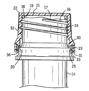
Referring to FIGS. 1 and 2, closure system 10 generally comprises molded
plastic container 12 including container shoulder 13. Container 12 includes
container
neck 14 extending upwardly from container shoulder 13. Container 12 has
dispensing
port 17 defined by pour lip surface 18 formed at container neck 14. Helical
external
threading 16 is located on container neck 14. Abutment surface 20 is
integrally formed
on, and extends substantially radially from, container neck 14 and is located
between
external threading 16 and container shoulder 13. Closure system 10 further
comprises
screw cap 22 having helical internal threading 24 of proper size and
construction for
rotatable engagement with external threading 16 on container neck 14.
CA 02303340 2000-03-08
WO 99/15422 PCT/US98/19594
-6-
Screw cap 22 includes top wall 21 and continuous cylindrical sidewall 32
extending
downwardly from top wall 21. Inner annular rim 30 and outer annular rim 31 are
integrally formed on, and extend downwardly from, sidewall 32 of screw cap 22.
Inner
annular rim 30 has a diameter which is less than the diameter of outer annular
rim 31.
Annular recess 33 is defined by inner and outer annular rims 30 and 31.
Closure system
further comprises gasket 36 which is retained on screw cap 22. Gasket 36 may
be
retained on screw cap 22 by being positioned in annular recess 33 and held
there by
being pressure-fitted into place. Alternatively, gasket 36 may be retained on
screw cap
22 other means, such as by being molded-in-place.
Container 12 may be manufactured by conventional molding procedures
using a thermoplastic material such as polypropylene, polyvinylchloride,
polyethylene
terphthalate, butadiene styrene, acrylics including acrylonitrile,
polytetrafluoroethylene,
polycarbonates and other thermoplastics. Screw cap 22 may be manufactured by
injection molding a thermoplastic material such as polypropylene,
polyvinylchloride,
polyethylene terphthalate, butadiene styrene, acrylics including
acrylonitrile,
polytetrafluoroethylene, polycarbonates and other thermoplastics. Gasket 36
may be
fabricated from resilient compressible material such as rubber, butadiene,
polytetrafluoroethylene (such as TEFLON ~, or injectable thermoplastic
elastomeric co-
polymers (such as KRATON ~ or C-FLEX ~). The materials used for the container
12,
screw cap 22 and gasket 36 should be selected from among materials compatible
with the
contents of the container, to prevent the materials from causing chemical
changes to the
contents of the container during storage and, also, to prevent the contents of
the container
from causing physical or chemical changes to the materials.
In a preferred embodiment as shown in FIG. 3, plug seal 40 extends
downwardly from top wall 21 and coaxially with sidewall 32, with plug seal 40
having a
diameter which is less than the diameter of sidewall 32. Plug seal 40 is
configured to
contact interior surface 19 of container neck 14. Plug seal 40 functions to
create a burner
to reduce the likelihood of contact between the contents of container 12 and
an exterior
CA 02303340 2000-03-08
WO 99/15422 PCT/US98/19594
_7_
portion of container 12 adjacent to dispensing port 17, including external
threading 16,
prior to the time the contents of container 12 are used. This contact might
otherwise
occur, for example, as a result of splashing caused by the handling of
container 12 during
shipping or storage. Plug seal 40 is constructed so that contact between plug
seal 40 and
interior surface 19 does not prevent engagement of gasket 36 with abutment
surface 20
upon engagement of internal threading 24 in screw cap 22 with external
threading 16 on
container neck 14. Also, abutment surface 20, screw cap 22 and gasket 36 are
constructed so that contact between gasket 36 and abutment surface 20 does not
prevent
a barrier from being created by plug seal 40 coming into contact with interior
surface 19,
upon engagement of internal threading 24 in screw cap 22 with external
threading 16 on
container neck 14.
In an alternate preferred embodiment, knife seal 50 is extended
downwardly from top wall 21 and coaxially with sidewall 32, with knife seal 50
having a
diameter which is less than the diameter of sidewall 32. Knife seal 50 is
configured to
contact pour lip surface 18. Knife seal 50 functions to create a barrier to
reduce the
likelihood of contact between the contents of container 12 and an exterior
portion of
container 12 adjacent to dispensing port 17, including external threading 16,
prior to the
time the contents of container 12 are used. Knife seal 50 is constructed so
that contact
between knife seal 50 and pour lip surface 18 does not prevent engagement of
gasket 36
with abutment surface 20 upon engagement of internal threading 24 in screw cap
22 with
external threading 16 on container neck 14. Also, abutment surface 20, screw
cap 22 and
gasket 36 are constructed so that contact between gasket 36 and abutment
surface 20
does not prevent a barner from being created by knife seal 50 coming into
contact with
pour lip surface 18, upon engagement of internal threading 24 in screw cap 22
with
external threading 16 on container neck 14.
External threading 16 and internal threading 24 are constructed to
establish sufficient contact between external and internal threadings 16 and
24 to
establish a sterile barrier or seal at gasket/container interface 25, located
between.gasket
CA 02303340 2000-03-08
WO 99/15422 PCT/US98/19594
-g_
36 and abutment surface 20, and to maintain the sterile barrier from the time
sterilization
is established until the time the contents of container 12 are to be used.
In a preferred embodiment, container 12 is extrusion blow molded and is
then subjected, to a well-known treatment, namely ultrasonic treatment
(sometimes
referred to as swaging), which smooths the molding seams created during the
molding
process, particularly along the points-of contact made between gasket 36 and
abutment
surface 20 when gasket 36 is fully seated against abutment surface 20.
In a preferred embodiment of the present invention, container 12 and
screw cap 22 are polypropylene and gasket 36 is polytetrafluoroethylene. Also,
screw
cap 22 and gasket 36 are molded simultaneously using a well-known technique.
One
such technique is a molding process know as two-shot injection molding. The
use of a
two-shot injection molding process causes screw cap 22 and gasket 36 to bond
together
thereby producing a unitary component. In a preferred embodiment, screw cap
22,
(including inner annular rim 30 and outer annular rim 31 integrally formed on
sidewall
32 of screw cap 22) is produced by injection molding. Next, gasket material is
injected
as a "second shot" and gasket 36 is molded between inner and outer annular
rims 30 and
31. In an alternate embodiment, gasket 36 is produced by injection molding.
Next, screw
cap material is injected as a "second shot" and screw cap 22 is molded onto
gasket 36.
Using two-shot injection molding to form gasket 36 and screw cap 22
can reduce the overall cost of the parts because the costs of handling,
shipping, and
stocking individual ly-molded gasket 36 and screw cap 22 parts may be avoided.
Also,
the cost of customized equipment which may otherwise be required to
subsequently sort
and assemble individually-molded gasket 36 and screw cap 22 parts may be
avoided.
Also, closure system 10 produced using the two-shot process can offer a
reduced risk of
a breach of sterility at a sterile barrier at cap/gasket interface 23 because
the cap/gasket
interface 23 is virtually eliminated when the materials used for screw cap 22
and for
gasket 36 reflow and bond during the second shot of the process. Screw cap 22
and
CA 02303340 2000-03-08
WO 99/15422 PCT/US98/19594
-9-
gasket 36 are essentially fused together. Also, the two-shot process can
produce a
closure system 10 in which dimensional variations which would otherwise affect
the fit
between gasket 36 and screw cap 22, and which would otherwise make the closure
system less reliable and more prone to failure, are negated by forming gasket
36 and
screw cap 22 into a unitary component.
In a preferred embodiment, container 12, screw cap 22, gasket 36 and the
contents of container 12 are assembled and then the assembly is sterilized.
Thus, the
contents of container 12 are sterilized along with that portion of the
assembly which is
located on the sterile side of the sterile barrier, including the interior of
container 12 and
an exterior portion of container 12 (including external threading 16) which
may come in
contact with the contents of container 12 during use. In an alternate
preferred
embodiment, screw cap 22, gasket 36 and container 12 are sterilized and then
closure
system 10 is filled and assembled using aseptic procedures.
To attach screw cap 22 to container 12, screw cap 22 is threadably
rotated downwardly on container neck 14, with engagement of internal threading
24 in
screw cap 22 with external threading 16 on container neck 14, until further
downward
movement of screw cap 22 is retarded as compressed resilient gasket 36 comes
into
resistive contact with abutment surface 20. Inner and outer annular rims 30
and 31 retain
gasket 36 and minimize movement and expansion of gasket 36 in directions other
than
the directions of applied compressive forces. Undesirable movements of gasket
36 are
thereby eliminated and closure system 10, having high integrity and
operational
reliability, is provided.
Screw cap 22 may be removed from container 12 so that the contents of
container 12 may be used. Subsequently, screw cap 22 may be reseated onto
container
neck 14.
Closure system 10 may include heat shrinkable outer member 60 which
CA 02303340 2000-03-08
WO 99/15422 PCT/US98/19594
-10-
is placed external to container 12 to envelop the cap/container interface,
thereby
providing a tamper evident seal.
FIG. 3 illustrates a preferred embodiment of closure system 10
incorporating the present invention in which a distal end 38 of gasket 36
forms an angle
"x" of between approximately 28 and 38 degrees relative to top wall 21 of
screw cap 22,
which, when brought into compressive contact with abutment surface 20, results
in the
establishment of compressive forces in both vertical and non-vertical
directions. Also, a
proximal end 39 of gasket 36 forms an angle "y" of approximately 35 degrees
relative to
top wall 21 of screw cap 22. These angles can increase the effectiveness of
the sterile
barner provided by closure system 10.
In a preferred embodiment, the exterior surface of sidewall 32 contains
knurls 70 so screw cap 22 can be removed more easily at the time of use.
From the foregoing, it will be observed that numerous modifications and
variations can be effected without departing from the true spirit and scope of
the novel
concept of the present invention. It will be appreciated that the present
disclosure is
intended as an exemplification of the invention, and is not intended to limit
the invention
to the specific embodiment illustrated. The disclosure is intended to cover by
the
appended claims all such modifications as fall within the scope of the claims.