Note: Descriptions are shown in the official language in which they were submitted.
CA 02303574 2000-03-30
THERMALLY INSULATED PACKAGING FOR TEMPERATURE SENSITIVE
PRODUCTS
This invention relates to a thermally insulated packaging system for
transporting temperature sensitive products such as medicines, vaccines,
laboratory
samples etc. comprising an outer shell with an opening, having one or more
thermally insulated walls which surround the therm211y sensitive product,
alongside
which is situated a refrigerant element, and whose walls form barriers
impervious to
flowable substances.
to
For a tong time now, there have been many different types methods or types
of packaging used for transporting thermally sensitive products such as
medicines,
vaccines, laboratories ete. each one with its own drawbacks.
One often used method involves the use of a conventional icebox, such as
those used by campers. But, on the one hand, such ice-boxes are not designed
to
maintain cold temperatures over many hours (or even days) without renewing the
refrigerant element placed inside them alongside the temperature-sensitive
product
being transported, and on the other hand, because their rigidity and large
volume
2 0 consume a great deal of space, especially so when being transported or in
storage
awaiting Their use, all of which amounts to an increase in overall costs.
Another widely used method is to use packaging material, which need not
necessarily be very impermeable, in order to enclose dry ice, which itself
surrounds
2 5 the temperature sensitive products being transported. As dry ice changes
from solid
to gaseous state without becoming a liquid i.e. it sublimes, it does not wet
either the
packaging or the product it contains. Nevertheless, the life of dry ice is
very limited
and, furthermore, its sublimation produces undesirable fumes and for this
reason
many haulage companies, including the airlines, forbid its use.
There currently also exist types of insulated box packaging that are composed
of rigid polyurethane four. This material is a closed-cell thermoplastic foam
with
excellent performance in terms of thermal insulation and impermeability as
well as
CA 02303574 2000-03-30
- 2 -
having a very Low density. The main drawback of such packaging is its
rigidity,
which makes the structure of the box occupy so much space. This is especially
inappropriate when the box is no longer being used, for example, during
transportation of the empty box between it manufacturing site and the end
user's
location as well as during storage, both at its place of manufacture and at it
end-
user's site until the moment the package is filled and forwarded to its
destination.
Consequently, there exists a great demand for a thermally insulated packaging
system that permits a reduction in volume, and therefore cost, during the
transport
and storage phases of it life-cycle, while it is not being used. The aim of
this
invention is meet that demand.
The above objective is attained, according this invention by providing a
temperature insulated packaging system for temperature sensitive products that
is
composed of several elements, each of which can be separated so as to permit a
compact and flat shape whilst undergoing transportation or storage, with the
component parts capable of being assembled and put into service by the user at
any
given moment.
2 0 This is achieved by the use in the general structure and in particular the
insulating material composition, of flexible material that permits the
components to
be folded and unfolded, thus to reducing to the minimum their volume when they
are
not in use and, at the same time, reducing the costs of transportation and
storage
while awaiting use.
The reduction in volume mentioned above is brought about by the use, as
material for the temperature insulated component of a flexible, open-cell
copolymer
foam, such isocyanate copolymer foam or polyurethane.
3 0 The flexibility of this material allows the production of a wrapping
comprised
of several flat panels, with it being possible for two or more of these panels
to be
joined together by split, articulated joint lines, so forming at least one
flat panel and,
by doing so, these panels andlor this flat panel assembly, only occupy a small
volume
CA 02303574 2000-03-30
during storage while awaiting use, and they permit user assembly prior to use
at any
moment
The thermal insulation properties of polymer foams derive from the
existence within the material of small thin-walled cells having very low
thermal
conductivity. In closed cell foams, a gas derived from the chemical reaction
occurring
during their manufacture, remains inside these cells for a long time. In the
case of
open-cell foams, however, this gas diffuses and mixes with the air around it
and is,
therefore, renewed continually. This explains the inferior thermal insulation
properties of the open-cell foams in comparison with those of closed-cell
foams.
Therefore, so as to take make the most of the potential for packaging volume
reduction of the' flexibility of open-cell foams (whilst losing none of
thermal
insulation properties) when the packaging is not in use, it is necessary to
introduce
an additional element to stop the diffusion of liquid andlor gaseous material
through
the foam.
With this in mind the new invention incorporates an internal impermeable
layer or fabric and an external impermeable layer or fabric which form
continuous
2 0 walls to both sides of the wrapping material. These layers or fabrics take
the form of
flexible infernal and external bags whose size and shape conform to that of
the
internal and external dimensions of the fully assembled thermahy insulating
package.
The bags mentioned above can be sealed by using any standard method that
wouid give a sufficiently hermetic seal e.g. thermal sealing, multiple
crimping of its
opening, folding and clamping of part of the opening, by means of a clamping
ring
or by means of a dovetail closure of the opening.
The bags are made of layers of metallic plastic which, in turn, are comprised
3 0 of one layer of aluminium laminated to a layer of polythene with the
thickness of the
external polythene layer being greater than that of the internal bag. The
aluminium
layer guarantees an excellent hermetic seal against gaseous diffusion while
the
polyhene layer forms a barrier against accidental leakage of the refrigerant
or of the
CA 02303574 2000-03-30
- 4 -
product being transported inside, not to mention the possibility of liquids
penetrating
from outside the package. Furthermore, the polythenelaluminium laminate offers
very good mechanical resistance properties.
With this arrangement, when the foam wrapping is fully extended and with
both the internal and external bags closed and in place, the result is a
structure with
thermally insulated walls surrounding an internal space which contains the
temperature sensitive product and the refrigerant, which, typically, consists
of water,
mixed with an additive that lowers its freezing point. Said additive could be
a salt
such as sodium chloride.
The refrigerant is enclosed within at least one container comprised of a
flattened, flexible plastic bag, with opposing walls .joined together by spot
welding
and having some partially sealed welded join-lines which delimit joint lines
of the
1 S various tillable panels. This bag, which has a removable stopper, is
supplied empty
but containing the appropriate amount of the additive mentioned above such
that
when it is not in use it occupies a limited volume during storage and
transportation.
The bag can be filled with water when its user anticipates its use; it is then
2 0 shaken in order to dissolve the additive, chilled in order to freeze its
contents and
then folded along the joint lines mentioned above in order to form the
refrigerated
closure for the temperature sensitive product.
In a preferred embodiment of the invention the package comprises two
2 5 identical refrigerated bags as described above, each one havin'e three
fillable panels
demarcated by .joint lines, said bags being able to be folded creating a U-
shape
structure which can be joined together to create a closure with rectangular
prismatic
structure whose dimensions are suitable for it to be housed within the
internal space
delimited by the thermally insulated wrapping mentioned earlier. The
temperature
30 sensitive product being transported is placed within said refrigerated
closure.
The whole assembly is protected by an outer shell formed by a conventional
cardboard box, such as a foldable box of corrugated cardboard. Text or logos
can be
CA 02303574 2000-03-30
- 5 -
printed on the outer surfaces of this cardboard box, which, should preferably
be pale
in colour so as to avoid, as much as possible, the absorption of external
thermal
radiation.
S These and other characteristics will become more apparent through the
following detailed description of an example of embodiment of the newly
invented
thermally insulated packaging, which makes reference to the drawings attached
in
which:
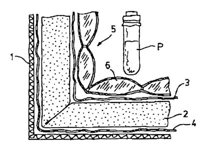
Fig. 1 is a partial view of an enlarged transverse section showing the
positions
of the various components comprising the packaging invention.
Fig. 2 is a perspective view of a flat sheet component of the thermally
insulated wrapping of the Fig. 1.
Fig. 3 is a perspecrive exploded view of the thermally insulated wrapping of
the Fig. 1.
Figs. 4 and 5 respectively show the internal and external flexible bags that
2 0 make up the respective impermeable layers or fabrics of the Fig. 1.
Fig. 6 is a plan view of the container for the refrigerant of the Fig. 1.
Fig. 7 is a perspective exploded view of the refrigerated closure of the Fig.
2 5 1 accomplished using 2 containers, as in Fig. 6.
In the transversal cross-section in Fig.l can be seen a corner of the
thermally
insulated package for temperature sensitive products according to the present
invention. Such temperature sensitive products could include e.g. medicines,
30 vaccines, laboratory samples, etc.
The packaging comprises an accessible shell -1-, insulated walls made from
a flexible, open-cell foam polymer or copolymer which form a wrapping -2-,
with
CA 02303574 2000-03-30
- 6 -
impermeable internal -3- and external -4- layers or fabrics that delimit the
wrapping
-2-, each of said layers or fabrics -3-. -4- being comprised of a plastic
laminate which
forms a barrier against the gaseous andlor liquid diffusing exchange across
the
wrapping -2-. This wrapping -2- marks the boundary of an internal space
suitable for
locating the temperature sensitive product -P- being transported, alongside
which
there is a refrigerant -6- enclosed in a cont2iner -5-,
The accessible shell -1-, wrapping -2-, external and internal layers or
fabrics
-3,4- and the container -5- for the refrigerant element -6- are held
separately during
their transport and storage while awaiting use, in a compact and flattened
stale and
lend themselves to being assembled and put into service whenever the user so
chooses.
The flexible polymer or copolymer foam mentioned above should preferably
be an either an isocyanate polymer foam or an open-cell urethane copolymer
foam.
The metallic plastic laminates mentioned above are used on both sides of the
wrapping -2-, in order to counter the adverse thermal insulation properties of
open-
cxll foams. These laminates -3- and -4- are comprised of a laminated polythene
layer
and aluminium layer, which impede the gas found within the polymer foam from
2 0 diffusing at the air around it as well as providing a hermetic barrier
against liquids.
The thickness of the polythene layer of the external laminate -4- is greater
than that
of the internal laminate -3-.
The aforementioned foamy copolymer wrapping -2- is comprised of at least
2 5 six panels -8- with bevelled edges -9- such that they can be fitted
together to form a
prismatic rectangular structure that demarcates the aforementioned internal
space.
l; igs. 2 and 3 show a practical example of the use of such a wrapping -2-,
which is shown to be formed by two flat sections -11-, each one forming part
of two
30 ,jointed panels -8- and another two single-panel pieces -12-. The flat
sheets -11-
include a split joint -10- which separates the two panels -8-, it being
possible to fold
over the panels along the joint -10-, forming an "L"-shape and with these
panels
capable of being joined to each other and to said single panel portions -12-
in order
CA 02303574 2000-03-30
_ -j _
to form the rectangular prismatic structure.
h is obvious that although in this example the prismatic structure has been
obtained through two double-panelled pieces and two single-panelled pieces,
the
same results could have been obtained using differently configurations such
as, for
example, two three-panelled pieces, one four-panelled piece, two
single~panelled
pieces, or even one single piece with six jointed panels. Nevertheless, the
factor
common to all of these is their flat configuration such that said flat pieces -
11- and
-12- occupy a relatively small volume whilst in transport or in storage
awaiting their
use. They can even be compressed, given their flexible foam construction, and
can
be assembled by the user at any given moment when he so desires.
So as to realise, practically, economically and simply, the impermeable
internal -3- and external -4- layers, which demarcate both the interior and
exterior
of the wrapping -2-, said layers -3-.~- are respectively composed of flexible
internal
bag -13- and a flexible external bag -14- (see Figs. 4 and 5) with dimensions
that
adjust, respectively, to the internal and external dimensions of the fully
assembled
wrapping -2- and prone to be close once assembled. It is evident that these
bags can
be transported and stored in a folded state so that they take up a minimum
amount of
Z 0 space when they are not in use.
The closing of the aforementioned internal and external bags -13. 14-, once
they are in place may be accomplished by means of any of the commonly used
methods e.g. thermal sealing, multiple crimping of its opening, folding and
clamping
2 5 of part of the opening, be means of a clamping ring or by means of a
dovetail closure
of its opening.
Figs 6 and 7 show the aforementioned container -5- for the refrigerant -6-,
which comprises a flattened, flexible plastic bag -15- with opposing walls
linked
30 together by welded joins -16- having partially sealed, soldered joint lines
-17- that
define the joint lines of various fillable panels -18-.
The refrigerant used -6- is composed of water and an additive -7- in order to
CA 02303574 2000-03-30
lower its freezing point. The additive used could be a salt, such as sodium
chloride.
The bag -5- comprises a removable stopper -19- and is supplied empty of
water but containing the aforementioned additive -7- so that it occupies a
reduced
volume during transportation and storage while awaiting use, and enabling the
user
to fill it with water. to shake, chill it to freeze its contents and then fold
it along said
joint lines -17- thus forming a refrigerated closure for the temperature
sensitive
product -P- as and when it should be required.
In the practical example illustrated, two identical bags -15- of the
aforementioned type as used, each one having two articulated joint lines -17-
that
demarcate three of the said filiable panels -18- and being capable of folding
into a
U-shape and of being fitted together, thus forming the aforementioned closure
with
a rectangular prismatic structure. It is apparent that said configuration
could be
accomplished using a different number or bags comprising a different number of
finable panels in a manner similar to that previously explained in relation to
the
wrapping -2-.
Finally, all the aforementioned elements, once fully assembled are placed
within the aforementioned shell, -l- (shown in a transverse section partial
view in
Fig. 1) which in the example of preferred use is constructed from a
conventional
cardboard box that, as with the rest of the package components, can be
separately
transported and stored in a flat state while awaiting its use so occupying a
minimum
amount of space.
A series of tests have been carried out in order to determine the capacity of
the packaging according to this invention to maintain a low temperature within
its
interior.
3 0 The tests were conducted on two different package specimens, namely: Type
1, designed to maintain temperatures of -20°C (-4°F) and Type 2,
designed to
maintain temperatures of 0°C (32°F). the specifications of which
be seen in Table
l , below.
CA 02303574 2000-03-30
- 9 -
Table 1.
PackaEina Specifications
Type I Type 11
-20C (-4F) 0C (32P)
External dimetLSions (cm) 68x58,5x53,331,5x27,5x30
Dimensions of in~ernal space (cm)32x27221 23x18,5x20,5
External volume (dm') 196 26 .
Volume of the internal space (dm3)18 9
External surface area (m2) 2,03 0.53
Surface area of internal space 0,42 0,26
(mi)
Average surface area (tn=) 0,93 0,37
In these tests refrigerant elements conforming to standard EKS 21 have been
used, i.e. the containers previously described and shown in the drawings have
not
been used. Therefore, the dimensions of the internal space refer to the
dimensions of
the internal space of the thermally insulated wrapping.
The test conditions for the Type I packaging were as follows:
Specimen: Type I: For Temperatures of -20°C (-4°f)
Refrifierant: 22 Refrigerant elements EICS 21
Eutectic Temperature approx. -21, 1°C (-6°F)
Refrigerant Energy: 2600 kJ
Sample: Test Tube filled with ice
(diameter 24 mm, length 90 mm, volume: approx. 40 cm3)
Transducer: Fe-Co thermocouple.
External Temperature: 23°C (73°F)
The resulting increase in temperature over time is shown in Table 2.
CA 02303574 2000-03-30
- 10 -
Table 2
Tncrease in Temperature over time for Type I package
TTME TEMPERATURE
hours (days) C
0,0 (0,00) -25,7 (-14,3)
0,5 (0,02) -25,6 (-14.1)
1,2 (0,04) -25,2 (-13,4)
2,0 (0,08) -24,9 (-12.8)
18,5 (0,77) -22,6 (-8,7)
21,0 (0,88) -22,4 (-8,3)
90,0 (3,75) -22,0 (-7,6)
96,0 (4,00) -220 (-7.6)
114,5 (4,77) -20,7 (-5,3)
118,5 (4,94) -20,3 (-4,5)
121,0 (5,04) -19,8 (-3,6)
The trial conditions for the Type II package where as follows:
Specimen: Type II: For Temperatures of 0°C (32°F)
Refrigerant: 8 Refrigerant elements E1CS 21
Eutectic Temperature approx. 0°C (32°F)
Refrigerant Energy: 1340 kJ
Sample: Test Tube filled with ice (diameter 24 mm, length 90 mm,
volume: approx. 40 cm')
Transducer: Fe-Co thermocouple.
2 5 External Temperature: 23 °C (73 °F)
The results of increase in temperature over time are shown in Table 3.
CA 02303574 2000-03-30
- 11 -
Table 3
Increase in Temperature over time for Type It package
TIME TEMPERATURE
hours (day's) C
0,0 (0,00) -17,1 (1,2)
0,5 (0,02) -15,0 (5,0)
I,0 (0.04) -13,5 (7,7)
1,5 (0,06) -12,1 (10,2)
2,0 (0,08) -11,0 (12,2)
S,0 (0,21) -5,1 (22,8)
6,0 (0,25) -3.5 (25,7)
7,0 (0,29) -2,0 (28,4)
8,0 (0,33) -1,4 (29,5)
9,0 (0,38) -0,7 (30.7)
18,0 (0.75) -0,6 (30,9)
19,0 (0,79) -0.6 (30,9)
20.0 (0,83) -0,6 (30,9)
21,0 (0,88) -0,6 (30,9)
22,0 (0,92) -U,6 (30.9)
2 0 24,0 (1,00) -0,6 (30,9)
26,0 (1,08) -0,6 (30,9)
28.0 (1.17) -0,6 (30,9)
30,0 (1,?5) -0,6 (30,9)
42,0 (1,75) -0,5 (31,1)
2 5 44,0 (1,83) -0,6 (30,9)
46,0 (1,92) -0,6 (30,0)
72,0 (3,00) -0,6 (30,9)
110,0 (4,58) -0,3 (31,5)
113,5 (4,73) 2,1 (35,8)
3 0 114,5 (4,78) 3,6 (38,5)
115,5 (4,81) 6,3 (41,5)
116,5 (4.85) 6,2 (43,2)
117,5 (4,90) 7.0 (44,6)
CA 02303574 2000-03-30
- 12 -
The results of the tests show that both in Type I package as well as in Type
II package the desired limit temperatures, -20°C (-4°F) and
0°C (32°F) were not
surpassed until more than 4 days from the start of the tests had lapsed.
The total thermal permeability coefficient ( value k) of the packages is
calculated as being the quotient of the refrigerant power and the product of
the mean
surface area and the temperature difference between the intema] and external
surfaces. The refrigerant power is derived from the quotient of the
refrigerant energy
used and the length of time during which the refrigeration temperature is
maintained.
Table 4
Coefficient of Thermal Permeability (Value k)
Package Type 1 Type II
-20C (-4F') 0C (32F)
Refrigerant Power (V~ 7,3 3,6
Internal Temperature (F) -22,3 -0,6
External Temperature (F) 73 73
Coefficient of Thermal Permeability0,17 0,4I
[WI(m'-xK)]
Knowing the coefficient of thermal permeability enables calculation of the
2 0 necessary refrigerant power, in other words, the number and type of
refrigerant
elements needed, as well as the period of desired temperature maintenance for
each
type of package.
An expert in the field could make some changes and variations without
2 5 straying Coo far from the scope of this invention, which is defined in the
claims
below.