Note: Descriptions are shown in the official language in which they were submitted.
CA 02303792 2000-03-08
METHOD FOR REGULATING A COATING PROCESS
Background of the Invention
The invention relates to a method for regulating a coating process
for applying a layer to a substrate.
During the application of layers to a substrate, it is necessary with
numerous manufacturing and treatment processes that a specific layer
thickness must be provided or maintained. During the manufacture of, for
example, compact discs (CD's), a coating agent, for example a lacquer
layer, or in the case of the manufacture of recordable CDs, so called CD-
Rs, a pigment is applied to a so-called plastic disc with a dispenser and
the lacquer or pigment is uniformly distributed over the disc by rotating the
disc and by utilizing cylindrical forces. During the coating process, the
thickness of the coating thus depends upon manyfactors, for example the
type and consistency of the coating agent, the existing temperature, the
speed or the duration, during which the substrate rotates. It is therefore
very difficult, over reasonably long periods of time, to maintain constant
parameters during the coating process that enable a coating of the
substrates with a constant layer thickness. To monitor the coating
thickness or the thickness layers provided thereby, it is therefore
necessary with conventional manufacturing processes to interrupt the
manufacturing process and to determine the respective layer thickness
of the applied layer via spot checks, and as a function thereof to alter the
-1-
LIT TRNSL of Altered PCTIEP981~5612 filed 4 September 1998 (Uwe Sarbacher, et
al.) - Az.2315
CA 02303792 2000-03-08
parameters for the manufacturing process that influence the layer
thickness, for example by appropriately altering the speed of the
substrate or the duration of the substrate rotation. The productivity of
conventional coating processes is therefore limited, which is particularly
disadvantageous especially during the manufacture of CDs or CD-Rs as
inexpensive mass produced products.
Although it is possible to provide the automatic manufacturing
equipment with expensive, very complicated measuring devices, such as
nuclear powered microscopic measuring devices; in order to deterr>line
the layer ofthickness during the coating process and as a function thereof
to alter the parameters for the coating, such measuring processes and
devices lengthen a checking preparation and require a long measuring
time. In addition, they are not only expensive but rather in particular are
also subject to breakdown and require a lot of maintenance, so that this
possibility is not suitable in conjunction with the manufacture of, for
example, CDs as mass produced items.
From the publication JP 06-223418 A, abstract in the data bank
WPI (Derwent), an apparatus is known with which the intensity of a
diffracted light beam of zero order is measured, which is produced when
the light beam is reflected at the surface of a transparent substrate that
is disposed on a turntable. As a result, the thickness of an applied layer
of an optical recording medium is measured.
-2-
LIT TRNSL of Altered PCT/EP98105612 filed 4 September 1998 (Uwe Sarbacher, et
al.) - Az.2315
CA 02303792 2000-03-08
The publication SU 947, 640 B, abstract in the data bank WPI
(Derwent) discloses a method for measuring thin layers according to
which the layer, the thickness of which is to be measured, is selectively
etched in order to measure a reflected defraction light beam and from that
to conclude the thickness of the layer. To measure the layer it is
therefore necessary to alter the layer itself. By etching a structure into the
layer that is to be measured, a "destructive" process is therefore utilized.
The publications H.H. Schlemmer, M. Machler, J. Phys., E.Sci.
Instrum. Vorrichtung. 18, 914 (1985); M. Machler, M. Schlemmer, Zeiss
Inform. 30. Vorrichtung. 16 (1988); U.S. Patent 4, 645, 349, U.S. Patent
4, 984, 894, U.S. Patent 4, 666, 305, WO 96-33387 A1 and EP 0 772 189
A2 disclose respective methods and apparatus for measuring layer
thicknesses according to which, however, diffraction processes are not
utilized and in addition regulating methods are not utilized in conjunction
with coating processes.
U.S. Patent 4, 457, 794 discloses a method for manufacturing
CDs. The substrate is provided with pre-grooves, and a recording layer
is applied to the substrate that is embodied with pre-grooves. A surface
region is radiated with a light beam from a light source, and the light beam
is then measured on the other side of the substrate by a photo sensor in
order to determine the applied layer thickness. The layer thickness is
thus determined by determining the light transitivity of the disc.
-3-
LIT TRNSL of Altered PCT/EP98I05612 filed 4 September 1998 (Uwe Sarbacher, et
al.) - Az.2315
CA 02303792 2000-03-08
U.S. Patent 4, 975,168 shows and describes a layer thickness
measuring process or layer thickness measuring apparatus in conjunction
with a sputter process for applying a layer onto a substrate, whereby a
projector having a halogen or xenon lamp emits a light beam having a
high intensity onto the substrate. The light beam is absorbed by a
spectra scope after it has passed through the substrate and the layers
applied thereon. The spectral distribution of the light beam serves as a
measure for the thickness of the applied layer.
It is an object of the invention to provide a method for regulating a
coating process for the application of a layer onto a substrate, with the
method being very simple, requiring little maintenance, and being
economical to use, and also enabling a reliable determination andlor
regulation of the layer that is to be applied onto a substrate during the
coating process.
This object is inventively realized by a method for regulating a
coating process for the application of a layer onto a substrate having a
diffracted structure, whereby the intensity or the intensity alteration of a
light beam or light bundle that falls upon the coated substrate and is
diffracted thereby is determined after its reflection andlortransmission for
at least the first or a higher order and is used as the actual value for the
regulation of the layer thickness. Due to the straightforward measures
and components for carrying out the inventive method, a reliable and
-4-
LIT TRNSL of Altered PCTIEP98/05612 filed 4 September 1998 (Uwe Sarbacher, et
al.) - Az.2315
" CA 02303792 2000-03-08
continuous determination of the layer thickness is possible during the
coating process with simple means and at low cost. The maintenance
expense for an apparatus for carrying out the method is also conceivably
low.
Since the substrate has structures, as is the case, for example, by
means of the so-called pre-grooves with CD-Rs, it is possible to
determine the intensity alteration of at least one diffracted light bundle,
for
example the first order or the second order or also a higher order of the
diffracted light bundle, and to utilize this as the actual or regulating value
for the regulation of the layer thickness. The intensity alteration in
particular of diffracted light bundles will be described in detail
subsequently with the aid of specific embodiments.
Pursuant to one advantageous embodiment of the invention, the
intensity or intensity alteration of the non-diffracted light beam is
determined.
Pursuant to a further very advantageous embodiment of the
invention, the intensity or intensity alteration of the non-diffracted andlor
diffracted light bundle is determined for at least one wavelength of the
light bundle. Due to the limitation to one or less wavelengths of the light
bundle, it is possible in certain applications to determine a defined
intensity.
However, it is particularly advantageous to simultaneously
-5-
LIT TRNSL of Altered PCTIEP98105612 filed 4 September 1998 (Uwe Sarbacher, et
al.) -Az.2315
' CA 02303792 2000-03-08
measure the intensity andlor the intensity alteration for a number of
wavelengths, as a result of which ambiguities due to interference effects
can be avoided.
The intensity or the intensity alteration of the diffracted light bundle
can be carried out in transmission andlor in reflection.
Pursuant to a further advantageous embodiment of the invention,
for regulation of a coating process not only the absolute intensity or the
absolute intensity alteration ofthe reflected and/or transmitted lightbeam,
but also the determination of the relative intensity' or intensity alteration
are possible and advantageous. In this connection, the relationship of the
intensities of the outgoing and of the incoming light bundles are
determined and are utilized as the actual or regulating value.
Pursuant to a further embodiment, the spectral distribution andlor
the alteration of the spectral distribution of a light beam that falls upon
the
coated substrate is determined after its reflection andlortransmission and
is utilized as the actual value for the regulation of the layer thickness.
Also in the case of the determination of the spectral distribution and/or of
the alteration of the spectral distribution this is possible for non-
diffracted
light beams or also with diffracted light beams, whereby the spectral
distribution or alteration thereof in the last case is possible and
advantageous not only for one order, for example the zero or the first
order, but also for multiple orders. Spectral photometers are preferably
-6-
LIT TRNSL of Altered PCTIEP98/05612 filed 4 September 1998 (Uwe Sarbacher, et
al.) - Az.2315
' CA 02303792 2000-03-08
utilized as receivers in the case of determination of the spectral
distribution or alteration thereof.
The light sources are advantageously lasers, light emitting diodes
(LED's), spectral lamps, halogen lamps, or thermal radiators, depending
upon the application and the conditions. It is also advantageous to filter
incoherent light spectra given off from a light source.
Pursuant to one advantageous embodiment of the invention,
observed values are provided for the target or intended values in
conjunction with the regulation. In order to avoid time consuming and
laborious tests and prior coating processes to determine these observed
values, it is also advantageous to utilize calculated values as target or
intended values for the regulation. Especially when the substrate and/or
the coating material is changed, and therewith a new disposition of the
layer profile is necessary, a determination of observed values for the
intended value of the regulation can be very time consuming. The target
values for the regulation are therefore advantageously computer
determined for a prescribed layer profile in order to save time. In this
connection, it is advantageous to utilize known calculation methods in
conjunction with the optics of these layers, as is known, for example, from
Born & Wolf, Principles of Optics, 6th Edition, Pergamon Press, especially
pages 51-70.
In conjunction with the coating of structured substrates, for
_7_
LIT TRNSL of Altered PCTIEP98/05612 filed 4 September 1998 (Uwe Sarbacher, et
al.) - Az.2315
' CA 02303792 2000-03-08
example for the manufacturer of CD-Rs, where the plastic substrate is
manufactured with an injection molding tool to form the pre-grooves
geometry, it is furthermore advantageous to undertake an analytic
correction of the wear of the injection molding tool, the geometry of which,
for example the depth of the pre-grooves, is noticeable during the
manufacture of a large number of plastic substrates.
The invention, as well as embodiments and advantages thereof,
will be explained in detail subsequently with the aid of an example of the
coating of a CD-R with the aid of the figures, which show:
Fig. 1, a schematic cross-sectional view through one
portion of a coated substrate for a CD-R, and
Fig. 2, a schematic illustration of the inventive method in
conjunction with the coating of a substrate having a
pre-groove geometry and being intended for CD-R
manufacture.
As shown in Fig. 1, a substrate has formed on an upperside
thereof a so-called pre-groove geometry, for example by injection molding
of the substrate 1. In this embodiment, the upper surface of the substrate
1 has so-called pre-grooves 2 having a width "a" of about 450 nm at a
constant spacing "b" of about 1600 nm, whereby the pre-grooves 2, at the
constant spacing "b", extend helically relative to one another. The pre-
_g_
LIT TRNSL of Altered PCTIEP98105612 filed 4 September 1998 (Uwe Sarbacher, et
al.) - Az.2315
CA 02303792 2002-06-17
grooves 2 have a depth "c" that typically lies in a range between 50 and
200 nm. Disposed on the substrate 1 is an applied pigment or dye layer
3 that essentially extends over the entire surface of the substrate 1 and
also fills the pre-grooves 2 of the substrate 1. Disposed above the pre-
grooves 2 that are filled with the pigment are respective so-called grooves
4 in the form of sinks that result during settling of the pigment into the pre-
grooves 2 of the substrate 1, and serve as a channel or track during the
recording and reading of the CD-R. Although the illustration shows a
right-angled shape for the groove 4 with the groove width, there normally
exists an inclined or gradual transition from the crown to the base. The
depth of the groove 3 is designated "d", while the thickness of the pigment
layer 3 in the regions beyond the pre-groove 2 and groove 4 is provided
with the reference symbol "f'.
The structure and embodiment of a CD-R as well as the pre-
grooved geometry thereof and the applied pigment layer is generally
known and is described, for example, in the article Holstlag, et al., Jpn.
J.AppLPhys. Volume 31, Part 1, Nr. 2 B (1992) pages 484-493.
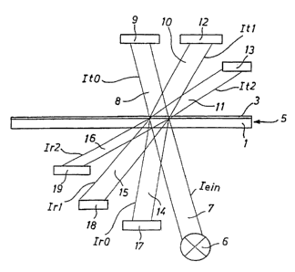
Fig. 2 schematically illustrates the CD-R 5 with the substrate 1 and
the pigment layer 3. A light source 6 emits an incoming light beam or
bundle 7 in an intensity Iein from below onto the CD-R 5, which goes
_g_
CA 02303792 2000-03-08
therethrough and has a non-diffracted transmission light bundle 8 having
an intensity ItO, in other words as a transmission beam of the diffraction
order zero, strikes a receiver 9, for example a spectral photometer, and
its intensity is measured. However, the incoming light beam 7 that strikes
the CD-R 5 from below is also diffracted at the pre-grooves 2, which due
to their uniform spacing "e" form a diffraction screen. As a consequence,
there results the transmission light bundle 10 of first order with the
intensity It1 and the transmission light bundle 11 with the intensity It2,
which fall upon respective further receivers 12 and 13 for measuring their
intensity, which receivers can again be spectral photometers. However,
the incoming light bundle 7 is also (partially) reflected in the CD-R 5 at the
transition between the substrate 1 and the pigment layer 3, so that in
conformity with the transmission light bundles 8, 10 and 11, reflection light
bundles 14, 15, 16 result that fall upon appropriate receivers or detectors
17, 18, 19. The reflection light bundle 14 is not diffracted and has the
intensity IrO. The reflection bundle 10 is the diffraction light beam of first
order with the intensity Ir1 and the reflection light bundle 16 is the
diffraction beam of second order with the intensity Ir2. It is to be
understood that the path of the beams could be reversed. In such a
case, the incoming light beam or bundle 7 of the light source 6 falls upon
the CD-R 5 from the side of the pigment layer 3. Many pigment layers
transmit at specific wavelengths only so little light that the additional
-10-
LIT TRNSL of Altered PCTIEP98I05612 filed 4 September 1998 (Uwe Sarbacher, et
al.) - Az.2315
CA 02303792 2000-03-08
reflection, e.g. at the transition between the substrate 1 and the pigment
layer 3, is very weak. A measurement is then practically not influenced
at all by such reflection.
The complex computation index of the material of the pigment
layer 3 is known as a function of the wavelength, i.e. can be measured by
known methods. Furthermore, the geometry of the pre-grooves 2 and
their orientation in the substrate 1, in other words the width "a" and the
depth "c' of the pre-grooves 2 as well as their spacing "b" from one
another is known. The pre-groove geometry is altered only slowly due to
the wear of the injection molding tool. The alteration of the pre-groove
geometry is therefore easy to regulate from time to time for determining
the thickness of the pigment layer 3, if it is not otherwise negligible.
In contrast, the surface relief of the pigment layer 3 is not known,
which is formed by the periodic structure of the grooves 4 with a groove
depth "d" and the groove width "e" (see Fig. 1 ).
This surface relief of the pigment layer 3, i.e. the depth "d" and the
width "e" of the grooves 4, can however be measured and established by
the light bundle intensities ItO, It1 and It2 of the transmitted light bundles
8, 10 and 11 andlor by the intensities IrO, Ir1 and Ir2 of the reflected light
bundles 14, 15 and 16.
Merely for the sake of completeness is mention made that the
uniqueness of the measured parameters ItO, It1 and It2, as well as IrO, Ir1
-11-
LIT TRNSL of Altered PCTIEP98/05612 filed 4 September 1998 (Uwe Sarbacher, et
al.) -Az.2315
CA 02303792 2000-03-08
and Ir2 is limited to phase differences that are less than half of the
utilized
light wavelengths. Since the depth "e" of the grooves 4, however,
normally lies between 50 nm and 200 nm, this means anyway in practice
and in particular with the transmission of the light bundle that there is no
limitation if light having a wavelength greater than about 600 nm is used.
In this connection, it is immaterial whether the diffracted light bundle is
measured in transmission or in reflection. When measuring in
transmission, the phase shift in the space interval 0 to 300 nm is
considerably less than half of the light wavelengths of the visible spectral
range. When measuring in reflection, there results for this spectral range
greater ambiguity, especially when illuminating from the substrate side.
These ambiguities can be eliminated only by a pre-knowledge ofthe more
narrow depth of field in the process. The usable depth of field in this case
can be expanded by simultaneously measuring at different wavelengths.
After the pre-groove geometry of the substrate 1, in other words
the width "a" and the depth "b" of the pre-groove 2, is known and is
constant, and the geometry of the pigment layer 3, in other words the
depth "d" and the width "e" of the grooves 4, can be measured, only the
constant thickness "f' of the pigment layer 3 is still unknown, which must
be determined and regulated during the coating process. This thickness
"f' affects the absorption of the transmitted, non-diffracted fight bundle
during an alteration during the application of the pigment layer 3, and
-12-
LIT TRNSL of Altered PCTIEP98105612 filed 4 September 1998 (Uwe Sarbacher, et
al.) - Az.2315
CA 02303792 2000-03-08
hence affects the relationship of the intensity It0 of the transmitted light
bundle of zero order and the intensity lein of the striking light bundle 7.
By measuring this relationship there therefore results a measurement for
the thickness "f' of the pigment layer 3 and a control actual value for
regulation of parameters of the coating process, for example a regulation
of the temperature of the pigment that is to be applied, or the speed or
duration of the substrate rotation.
Ifthe danger of ambiguities of the measurement ratio It011ein exists
due to interference effects, it is additionally advantageous and expedient
to simultaneously measure It011ein for a number of wavelengths, for
example by using a spectral photometer.
For the target or desired magnitudes during the regulation it is
sufficient if observed or empirical values are prescribed. A numeric
determination of the values "d", "e", "f' is not necessary for a regulation.
The determination of such empirical or observed values can, however,
require a lot of time. In particular, when the type of pigment is changed
a new provision of the layer profile is necessary. In order to save time, it
is then advantageous to numerically determine the target values for a
prescribed layer profile. For this purpose, the transmission through the
substrate 1 and the pigment layer 3 is locally calculated for one period of
the periodic structure utilizing conventional calculation processes for thin
layers. Subsequently, there is effected for the calculated, complex
-13-
LIT TRNSL of Altered PCTIEP98105612 filed 4 September 1998 (Uwe Sarbacher, et
al.) -Az.2315
CA 02303792 2000-03-08
amplitudes a resolution in flat waves, i.e. a Fourier transformation is
carried out. Squaring the amplitude of the flat waves delivers the intensity
of the individual diffraction orders. This simplified method of proceeding
is physically not exact, since the coupling of the waves of different orders
cannot be taken into account. Nonetheless, in practice there results
sufficient precision, since the depths of the structures, in other words the
values "c" and "d", are at most 200 nm, in other words much less than
their periodicity, i.e. of the pre-grooves 2 or grooves 4 of 1600 nm relative
to one another.
The invention has previously been described with the aid of one
exemplary embodiment in conjunction with CD-R's. However, to one
having ordinary skill in the art modifications and embodiments are
possible without thereby deviating from the inventive concept.
Furthermore, it is also possible by appropriate use of the inventive
method at various locations of a substrate to determine if the layer
thickness is uniform over the entire surface.
-14-
LIT TRNSL of Altered PCTIEP98/05612 filed 4 September 1998 (Uwe Sarbacher, et
al.) - Az.2315