Language selection

Search

Patent 2304053 Summary

Third-party information liability

Some of the information on this Web page has been provided by external sources. The Government of Canada is not responsible for the accuracy, reliability or currency of the information supplied by external sources. Users wishing to rely upon this information should consult directly with the source of the information. Content provided by external sources is not subject to official languages, privacy and accessibility requirements.

Claims and Abstract availability

Any discrepancies in the text and image of the Claims and Abstract are due to differing posting times. Text of the Claims and Abstract are posted:

  • At the time the application is open to public inspection;
  • At the time of issue of the patent (grant).
(12) Patent Application: (11) CA 2304053
(54) English Title: A LACING HOOK FOR LACED FASTENINGS
(54) French Title: CROCHET DE LACAGE POUR ELEMENTS DE FIXATION LACES
Status: Dead
Bibliographic Data
(51) International Patent Classification (IPC):
  • A43C 3/00 (2006.01)
(72) Inventors :
  • GALLO, TIZIANO (Italy)
  • BISSACCO, RINO (Italy)
(73) Owners :
  • GALLO, TIZIANO (Italy)
  • BISSACCO, RINO (Italy)
(71) Applicants :
  • GALLO, TIZIANO (Italy)
  • BISSACCO, RINO (Italy)
(74) Agent: OYEN WIGGS GREEN & MUTALA
(74) Associate agent:
(45) Issued:
(86) PCT Filing Date: 1998-09-03
(87) Open to Public Inspection: 1999-04-01
Availability of licence: N/A
(25) Language of filing: English

Patent Cooperation Treaty (PCT): Yes
(86) PCT Filing Number: PCT/EP1998/005593
(87) International Publication Number: WO1999/015043
(85) National Entry: 2000-03-15

(30) Application Priority Data:
Application No. Country/Territory Date
PD97A000211 Italy 1997-09-19

Abstracts

English Abstract


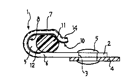
A lacing hook for laced fastenings is described and comprises a first cheek
(6) and a second cheek (7) disposed opposite one another and defining between
them a channel (8) with a base surface (9) defining a lacing surface for the
hook, the base of the channel (8) being formed integrally with the lacing hook
and the base surface (9) of the channel having a substantially toroidal shape.


French Abstract

L'invention porte sur un crochet de laçage pour éléments de fixation lacés, ce crochet comprenant un premier rebord (6) opposé à un second rebord (7), ces deux rebords formant entre eux un canal (8) doté d'une surface de base (9) formant une surface de laçage du crochet. La base du canal (8) fait partie intégrante du crochet de laçage et la surface de base (9) du canal est de forme pratiquement toroïdale.

Claims

Note: Claims are shown in the official language in which they were submitted.


CLAIMS

1. A lacing hook for laced fastenings, comprising a first
cheek (6, 56) and a second cheek (7, 57), disposed opposite
one another and defining between them a channel (8, 58)
with a base surface (9, 59) of the channel defining a
lacing surface for the hook, the base of the channel (8,
58) being formed integrally with the lacing hook and the
base surface (9, 59) of the channel (8, 58) having a
substantially toroidal shape, characterized in that the
toroidal surface is defined by the rotation of a first arc
(12) of a circle about an axis on which a second arc (13)
of a circle is centred, the first and second arcs (12, 13)
extending through respective angles of between 15° and 180°
and preferably close to the higher value indicated, and in
that said hook comprises peripheral edges (15), said edges
being turned towards the outside of the channel (8, 58) at
least in a region in which the lace enters and leaves the
channel (8, 58) of the hook.
2. A lacing hook according to Claim 1, in which the channel
(8) is open at the side opposite the base surface (9).
3. A lacing hook according to any one of the preceding
claims, comprising restraining means for holding the lace
in the channel.
4. A lacing hook according to Claim 3, in which the
restraining means comprise a narrow portion (14, 21) of the
channel (8) in the region of its mouth (10).
5. A lacing hook according to Claim 4, in which the narrow
portion is defined by a lip (14, 21) formed as an extension
of the second cheek (7).
6. A lacing hook according to Claim 5, in which the lip
(21) is bent towards the inside of the channel (8) to form
an eye.
7. A lacing hook according to one or more of the preceding


7


claims, in which the channel (8) is closed on the side
opposite the lacing surface.
8. A lacing hook according to one or more of the preceding
claims, comprising a first portion and a second portion,
the first portion having means (52, 53) for attaching the
hook to the footwear, the lacing surface being formed on
the second portion, and the second portion being mounted
far pivoting on the first portion.
9. A hook according to one or more of the preceding claims,
comprising a rivet-like appendage (31) formed integrally
with the hook and extending from the first cheek (6), away
from the channel (8).

Description

Note: Descriptions are shown in the official language in which they were submitted.


2.~ % 12 ' 99 09: 42 '8'09 051031 gar r.iL~, y
A lacing hook for laced fastenings
Tecr.nical Fie' d
The presen t invention relates tc a l ac:.ng hook fcr
laced fastenings according to the prea:..ble to t!:e main
claim.
Background Art
In the technical f~.eJ.d of footwear with lacQd
fastenings, lacing hooks are used widely for guidi.~.g the
laces suitably on the upper of the footwear.
A lacing hook having the features outlined abcve is
also known from DE 1951910 and DE 1800135.
One of the prcblems encountered with known -pacing
hooks lies in the resistance due to friction ~.rhich these
hooks offer to the sliding of the lace, wrich ::ay .«ake it
difficult to faster. the footwear with the desired te::sion.
In cider partially to prevent this prob~em, it is
known to brovide suitably-shaped inserts in the base of the
channel of the hook to improve the sliding of t:e lace. Tn
these solutions, however, the tens:.ons prod::ced ~ n the
laces, as well as the frictional forces present, tend to
stress the aforementioned inserts until they are pulled off
the corresponding hooks, compromising the fastening of t:e
footwear. Moreover, these solutions req~~re pre-asse:,~,bly
of the hook w,~th the corresponding insert.
Disclosure of the invention
:he problem upon. which the present inversion is based
is that of providing a lacing hock w'.:ich is ces'_gned
structura 1 1 y and functionally to preve::t a~.l of t::e
probl emS cOmp~.a .n ed of with refere.~.ce to the prier ar t
mentioned.
This prcb-em ;.s solved by the inventic:. by a lac:.:.g
hook formed in accordance with the follow'.ng c~ay:.is.
A.~ advantage achieved by the hook of the present invention
CA 02304053 2000-03-15
AM~i~~='~ ~~~T


WO 99/15043 PCT/EP98/05593
is that it permits effective and rapid sliding of the lace with
low sliding friction during both fastening and unfastening, at
the same time forming a particularly strong hook which is free
of sharp surfaces, and which can hold the lace in position once
it is housed in the channel of the hook.
Another advantage is that of providing a lacing hook with
a monolithic structure such that it requires no pre-assembly
operations.
Brief descriptions of the drawings
Further advantages and characteristics of the invention
will become clearer from the following detailed description of
some preferred embodiments thereof described by way of non-
limiting example with reference to the appended drawings, in
which:
Figures 1 and 2 are a plan view and a side elevational
view, respectively, of a first embodiment of the lacing hook
according to the invention,
Figure 3 is a view corresponding to Figure 2 of a second
embodiment of the lacing hook according to the invention,
Figures 4 and 5 are views corresponding to Figures 1 and
2, respectively, of a third embodiment of the lacing hook
according to the invention,
Figure 6 is a view corresponding to Figure 5 of a fourth
embodiment of the lacing hook according to the invention,
Figures 7 and 8 are a plan view and a side elevational
view, respectively, of a fifth embodiment of a lacing hook
according to the present invention,
Figure 9 and 10 are views corresponding to Figures 7 and
8, respectively, of a sixth embodiment of the lacing hook
2
CA 02304053 2000-03-15


WO 99/15043 PGT/EP98/05593
according to the invention.
Best mode of carrying out the invention
With reference to Figures 1 and 2, a first embodiment of
a lacing hook formed in accordance with the present invention
is generally indicated 1. The hook 1 comprises an attachment
plate 2 having through-holes 3 for the fixing of the hook 1 to
a respective portion 4 of a footwear upper, shown only
partially (Figure 2), by means of rivets 5 or similar fixing
means. The plate 2 is extended to form a first cheek 6 and a
second cheek 7 together defining a channel 8 which has a closed
base 9 and is open on the opposite side with a mouth 10.
The surface of the base 9 defines a lacing surface over
which a lace 11 can be guided for sliding and which has a
substantially toroidal shape. The toroidal surface of the base
9 is defined by the rotation of a first arc of a circle,
indicated 12 in Figure 2, about an axis on which a second arc
of a circle, indicated 13 in Figure 1, is centred. It should
be noted that both arcs 12 and 13 extend through respective
angles of between approximately 15° and 180° and preferably in
the region of the higher value indicated above. The lace 11
is thus guided on the curved base of the channel 9 without
breaks in continuity, particularly in the regions in which the
lace enters and leaves the hook (Figure 1), thus offering the
best possible sliding and preventing damage to the lace due to
repeated changes in its curvature. It is envisaged that the
curvature of the arc 14 may be variable along its length.
It should also be noted that the base 9 with the toroidal
surface, is formed integrally with the hook 1 during the
formation thereof, for example, by the stamping technique. The
3
CA 02304053 2000-03-15


WO 99/15043 PCT/EP98/05593
hook 1 thus produced therefore has a monolithic structure which
can make it particularly strong.
A narrow portion formed at the mouth 10 of the channel 8
is defined by a lip 14 at the end of the cheek 7, facing the
opposite cheek 6 and projecting towards the latter in order to
restrict the mouth.
The narrow portion of the mouth 10 constitutes restraining
means for holding the lace 11 close to the lacing surface of
the base 9 once the lace is engaged in the channel 8.
In the regions in which the lace enters and leaves the
channel 8 of the hook, the peripheral edge 15 of the hook is
turned over towards the outside of the channel and is bent onto
the corresponding cheek so as to allow for ample sliding of the
lace engaged in the hook, at the same time eliminating any
regions in which there is friction and consequently wear of the
lace against the lacing surfaces of the hook.
With reference to Figure 3, a second embodiment of the
lacing hook formed in accordance with the present invention is
indicated 20. Details similar to those of the previous
embodiment are indicated by the same reference numerals. The
hook 20 differs from the hook 1 in that a narrow portion at the
mouth l0 is produced by the bending of an end lip 21 of the
cheek 7 towards the inside of the channel to form an eye.
Figures 4 and 5 show a third embodiment of the lacing hook
according to the invention, generally indicated 30. Unlike the
hooks of the previous embodiments, the hook 30 has a rivet-
shaped appendage 31 formed integrally with the hook and
projecting from the cheek 6 in order to engage a corresponding
hole formed in the footwear upper in order to fix the hook to
4
CA 02304053 2000-03-15


WO 99/15043 PCT/EP98/05593
the footwear.
In Figure 6, a variant of the hook of Figures 4 and 5 is
indicated 40 and differs in that, as in the hook 20, it has a
narrow portion at the mouth 10 formed by bending of the end lip
of the cheek 7 towards the inside of the channel 8 to form an
eye.
With reference to Figures 7 and 8, a fifth embodiment of
the lacing hook according to the present invention is indicated
50. The hook 50 comprises a first portion and a second portion
articulated to one another. The first portion comprises an
attachment plate 52 having a single hole 53 for the fixing of
the hook to the footwear upper by means of a rivet or the like.
The second portion comprises a pair of opposed cheeks 56, 57
together defining a duct 58 having, on one side, a base 59 the
toroidal-shaped surface of which constitutes a lacing surface
for the sliding of a lace, not shown in the drawings. The duct
58 is closed on the opposite side by an extension of the cheek
57 which extends as far as the opposite cheek 56. Once the
lace has been disposed in the duct 58 for lacing, it thus
remains in position engaged in the hook until it is
deliberately unthreaded from the duct. It should be noted
that, since the second portion of the hook 50 is pivotable in
a plane substantially perpendicular to the footwear upper
(Figure 7), self-alignment of the second portion which is
subject to the lacing tensions is facilitated and the sliding
of the lace in the lacing hook during tensioning and/or release
of the lace during fastening and unfastening of the footwear
is thus improved.
Figures 9 and 10 show a sixth embodiment of the lacing
CA 02304053 2000-03-15


WO 99/15043 PCT/EP98/05593
hook according to the invention, generally indicated 60. The
hook 60 differs from the hook of the previous embodiment
substantially in that it has a monolithic structure in which
the two hook portions are formed as a single piece. A
plurality of projections, indicated 61, serve to improve the
anchorage of the hook to the portion of the upper on which it
is fitted.
The invention thus solves the problem set, achieving the
advantages indicated above in comparison with known solutions.
6
CA 02304053 2000-03-15

Representative Drawing
A single figure which represents the drawing illustrating the invention.
Administrative Status

For a clearer understanding of the status of the application/patent presented on this page, the site Disclaimer , as well as the definitions for Patent , Administrative Status , Maintenance Fee  and Payment History  should be consulted.

Administrative Status

Title Date
Forecasted Issue Date Unavailable
(86) PCT Filing Date 1998-09-03
(87) PCT Publication Date 1999-04-01
(85) National Entry 2000-03-15
Dead Application 2004-09-03

Abandonment History

Abandonment Date Reason Reinstatement Date
2003-09-03 FAILURE TO REQUEST EXAMINATION
2003-09-03 FAILURE TO PAY APPLICATION MAINTENANCE FEE

Payment History

Fee Type Anniversary Year Due Date Amount Paid Paid Date
Application Fee $150.00 2000-03-15
Maintenance Fee - Application - New Act 2 2000-09-05 $50.00 2000-03-15
Maintenance Fee - Application - New Act 3 2001-09-03 $50.00 2001-07-30
Maintenance Fee - Application - New Act 4 2002-09-03 $100.00 2002-07-29
Owners on Record

Note: Records showing the ownership history in alphabetical order.

Current Owners on Record
GALLO, TIZIANO
BISSACCO, RINO
Past Owners on Record
None
Past Owners that do not appear in the "Owners on Record" listing will appear in other documentation within the application.
Documents

To view selected files, please enter reCAPTCHA code :


To view images, click a link in the Document Description column. To download the documents, select one or more checkboxes in the first column and then click the "Download Selected in PDF format (Zip Archive)" or the "Download Selected as Single PDF" button.

List of published and non-published patent-specific documents on the CPD .

If you have any difficulty accessing content, you can call the Client Service Centre at 1-866-997-1936 or send them an e-mail at CIPO Client Service Centre.


Document
Description 
Date
(yyyy-mm-dd) 
Number of pages   Size of Image (KB) 
Representative Drawing 2000-06-09 1 6
Abstract 2000-03-15 1 47
Description 2000-03-15 6 241
Claims 2000-03-15 2 65
Drawings 2000-03-15 2 41
Cover Page 2000-06-09 1 34
Assignment 2000-03-15 2 100
PCT 2000-03-15 12 413
Fees 2002-07-29 1 43