Note: Descriptions are shown in the official language in which they were submitted.
CA 02304233 2000-03-14
.,
, ~ . ,
., . , ,
",
1 ,, , ", ,
.., ~, "
' ' ~ ~ PATENT
Attorney Docket No. 016002-001300
LIGHT DELIVERY CATHETER AND PDT
TREATMENT METHOD
BACKGROUND OF THE INVENTION
It has been found that certain abnormal growths,
such as certain cancerous tissue and atheromatous plaque, have
IO an affinity for certain photosensitizing agents.
Photosensitizing agents are compounds that, when exposed to
light, or light of a particular wavelength or wavelengths,
create Oz radicals which react with the target cells.
Examples of such agents include texaphyrins, hematoporphyrin,
chlorins, and purpurins. In the case of living cells, such as
cancer tumors, an appropriate photosensitizing agent is used
to create the OZ radicals which kill the target cells. In
other situations, such as when it is desired to destroy
atheromatous plaque tissue, an appropriate photosensitizing
agent is activated to destroy the plaque by lysis (breaking
up) of such plaque; mechanisms other than lysis may also be
involved.
IlNS~'2T /~->
SUN~iARY OF THE INVENTION
The present invention is directed to a light-
delivery catheter and a photodynamic therapy (PDT) treatment
method which uses a perfusion balloon to permit unintez~rupted
fluid flow through a hollow body organ, such as a blood
vessel , the heart , ~ bronchi , colon, ~esoyp'~agus , or urethra of a
patient, while irradiating the walls of the organ. The
intensity of the light irradiating the organ walls is
preferably equalized using one or more techniques.
The light delivery catheter includes a sheath
defining a lumen with a balloon mounted to the sheath in fluid
communication with the Lumen. A light guide is at least
partially housed within the sheath and has a light-radiating
portion (also called the light source) within the balloon.
The sheath may or may not extend partly or fully within the
pi~IiENOED SHEET
CA 02304233 2000-03-14
' . " ,
, ,
. , ", ",
. , . ~ ,
. . , ~" " a,
t ..
Insert A
EP 0 664 104 A2 discloses a catheter in which a perfusion balloon forms a u-
shaped perfusion channel. Occluding agents that are liquid until exposed to
certain radiation
are exposed to light from an optical fiber as the occluding agent exits the
catheter to seal the
aneurysm or branch vessel opening by forming an occluding cast. U.S. Patent
No. 5,370,608
shows exposing the interior of a body lumen to light through an opening near
or within a
balloon. U.S. Patent No. 5,470,314 discloses a perfusion balloon catheter
defining a central
perfusion channel. U.S. Patent No. 4,581,017 discloses a lobed balloon
surrounding a
catheter. U.S. Patent 5,454,794 illustrates a steerable catheter with a light
diffusing tip.
PA 3022453 vl
~N~NDED S~~
CA 02304233 2000-03-14
WO 99/15236 PCT/US98/19250
2
balloon. The balloon defines one or more perfusion channels
when the balloon is inflated so that fluid can continue
passing through the organ housing the inflated balloon.
In use, the balloon. is positioned within the hollow
body organ. Depending on the particular therapy, target
tissue may or may not be (but typically is) inoculated with an
appropriate photosensitizing agent. The target tissue may or
may not be a part of the hollow body organ. For example, the
hollow body organ may be a section of artery and the target
tissue may be the artery itself, tissue external of the artery
or atheromateoua plaque within the artery. The target tissue
is irradiated, typically causing destruction of the target
tissue as is desired. The light irradiating the organ wall is
preferably of generally equal intensity. The light source can
IS be a laser light source or other light source with suitable
light characteristics.
Irradiation can be achieved in whole or in part in
several different ways. The light irradiated from the Light
source, typically a cylindrical light diffuser, can be
diffused so that it does not travel along mainly radially-
directed paths. This diffusion can be accomplished by adding
light-diffusing material into the normally light-transparent
material of the balloon. The light source itself can be
configured to radiate diffused light. Diffusion can also be
provided by using a plurality of light sources within the
balloon or adding light diffusing material within the fluid,
typically a liquid, used to inflate the balloon. Also, the
intensity of the irradiation of the vessel walls can be
equalized by applying light-absorbing material to selected
regions of the balloon, configuring the perfusion channels so
each radial ray passes through equal lengths of perfusion
channels, or otherwise equalizing the light attenuation along
radially directed paths from the light source.
The size of the one or more perfusion channels can
be selected according to the amount of perfusion desired for a
particular patient for a p-articular procedure. This is
typically dictated in a large part by the condition of the
patient and the particular hollow body organ being treated.
CA 02304233 2000-03-14
wo ~ns~ PCTNS98/192s0
3
Also, for hollow body organs that are at different locations
on the body, such as blood vessels, the location of the target
site also affects the size of the perfusion channels.
A primary advantage of the invention is that PDT
treatment methods can be carried out within a hollow body
organ, typically a blood vessel, over a relatively extended
period of time, such as one-half hour or longer, while
permitting, for example, blood to continue passing through the
organ. This permits the use of light at lesser intensities
but over a longer period of time to be used to irradiate the
inoculated target tissue to help prevent damage to adjacent
healthy tissue. In addition, the provision of one or more
perfusion channels provides fluid flow past the balloon during
PDT treatment without the need to inflate and deflate the
balloon in time with the beating heart. The perfusion
channels also help to prevent patient discomfort and possible
damage to, for example, limbs whose blood supply is cut off
for too long a time.
The balloon inflation fluid can be a liquid or a
gas. For example, in cardiovascular situations a liquid, such
as sterile saline or sterile water, would typically be used,
while in gastroenterology situations air or nitrogen can be
used to inflate the balloon.
The fluid passing along the perfusion channels
typically does not have the same light transmisaive
characteristics as either the balloon or the fluid that
inflates the balloon. For example, when the hollow body organ
is a blood vessel, blood tends to attenuate the intensity of
the light much more than the balloon or the fluid within the
balloon. Therefore, light rays that pass through a greater
length of blood will strike the organ wall with a lower
intensity than rays that pass through a lesser length of
blood. The present invention recognizes this and contemplates
the use of one or more methods or schemes (mentioned above) to
help equalize the intensity of the light irradiating the organ
wall, including diffusing the light, using light-absorbing
material at selected regions on the balloon, and configuring
CA 02304233 2000-03-14
WO 99/15236 PCT/US98/19250
4
the balloon so that the segments of radially directed light
passing through the perfusion channels are of equal length.
The invention can find~particular utility when there
is a great selective uptake of the photosensitizing agent into
the target tissue. Under this circumstance, the provision of
highly equal light intensity irradiating the organ wall is not
as critical as when the uptake of the photosensitizing~agent
is not as selective.
Other features and advantages of the invention will
appear from the following description in which the preferred
embodiments have been set forth in detail in conjunction with
the company drawings.
BRIEF DESCRIPTION OF THE DRAWINGS
Fig. 1 is a simplified overall view of a catheter
assembly made according to the invention;
Fig. 2 is an enlarged cross-sectional view of the
inflated perfusion balloon of Fig. 1 within a blood vessel;
Fig. 2A illustrates an alternative embodiment of the
distal end of one of the arms of the perfusion balloon of
Fig. 2;
Fig. 2B illustrates an enlarged central portion of
an alternative embodiment of the invention of Fig. 2 in which
the sheath extends into the balloon to surround the
cylindrical diffuser;
Fig. 3 is a view similar to that of Fig. 2, but of
an alternative embodiment of the invention in which the
perfusion channels are relatively small compared to the
perfusion channels of the embodiment of Fig. 2;
Fig. 4 illustrates a further embodiment of the
invention in which the arms of the perfusion balloon extend
radially and tangentially;
Fig. 5 illustrates another embodiment of the
invention in which the arms of the perfusion balloon are
generally Y-shaped;
Fig. 6 illustrates a still further embodiment of the
invention in which the balloon has a wagon wheel
configuration;
CA 02304233 2000-03-14
wo ~nsz36 rc~rius9snnso
Figs. 7A-7C illustrate a cylindrical diffuser, a
spherical diffuaer'and a flat end diffuser, respectively; and
Fig. 8 illustrates an-embodiment of the invention in
which the balloon is in the form of a generally cylindrical
5 sleeve.
DESCRIPTION OF THE PREFERRED EMBODIMENTS
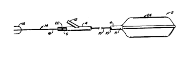
Fig. 1 illustrates a catheter assembly 2 comprising
a sheath 4 having proximal and distal ends 6,8. Sheath 4 is
hollow and defines a central lumen l0 therein. Proximal end 6
has a Y-port 12 which fluidly communicates with central
lumen 10. A light guide 14 includes an optical fiber I6 which
extends along lumen 10. Optical fiber 16 terminates at its
proximal end at a light receptor end 18 and at its distal end
at a cylindrical diffuser 20 (see Fig. 2). Although not
shown, a guidewire, for example, could also be used as a part
of catheter assembly 2. A fluid seal 22 is used to provide a
seal between optical fiber 16 and sheath 4 at proximal end 6.
A perfusion balloon 24 is mounted to distal end 8 of
sheath 4. Balloon 24, see Fig. 2, has an x or + cross-
sectional shape and defines a similarly-shaped balloon
interior 26 therein. Balloon interior 26 is fluidly coupled
to central lumen 10 so that interior 26 can be pressurized
with an appropriate fluid, such as sterile saline or sterile
water in the case of cardiovascular use. Sheath 4 may extend
part way into or fully through interior 26 of balloon 24, see
Fig. 2B, to surround part or all of diffuser 20. Sheath 4 may
also extend all the way through interior 26 of balloon 24 and
have a hole at its distal end to allow placement over a-
guidewire; inner space of sheath 4 would then be sealed from
interior 26 of balloon 24 to allow inflation of the balloon.
Balloon 24 has a number of arms 28 which partially
define perfusion channels 30. Therefore, balloon interior 26
includes a central region 29 housing diffuser 20 and several
arm regions 31. Accordingly, when balloon 24 is inflated to
its condition of Fig. 2, the distal ends 32 of arms 28 press
against the vessel wall 33 of the blood vessel. As is shown
in Fig. 2, cylindrical diffuser 20 (see Fig. 7A) is generally
CA 02304233 2000-03-14
WO 99/15236 PGT/US98/19250
6
centrally placed within the blood vessel and within
balloon 24. Conventional cylindrical diffusers 20 typically
radiate light along radial paths, e.g. paths 34, 34a, 34b.
Each radial path 34 has a perfusion segment 36 and a balloon
interior segment 38 which together constitute radial
transmission path 34. That is, segment 36 is that portion of
path 34 that passes through perfusion channel 30 while
segment 38 is that portion of path 34 that passes through
. balloon interior 26. Similarly, path 34a includes a perfusion
segment 36a and a balloon interior segment 38a. However,
path 34b does not pass through a perfusion channel 30 so that
the entire path 34b is constituted by a balloon interior
segment 38b.
Within a blood vessel, the fluid within perfusion
channels 30 will be blood which attenuates the intensity of
the light radiated from diffuser 20 to a much greater extent
than the water or saline within balloon interior 26.
Therefore, the intensity of the light beam passing along
radial path 34 and striking vessel wall 33 will be of lesser
magnitude than the intensity at vessel wall 33 along path 34a;
the intensity at the end of path 34b will be the greatest of
the three. To help counteract this difference in light
intensity, portions or segments of balloon 24 are coated with
a light-absorbing material, such as doped urethane (black) or
other black-doped polymer balloon catheter materials. This
may also be accomplished with other light-absorbing or light-
reflecting materials. For example, the distal end 32 of
arms 28 can be coated with a light-absorbing material as
suggested by arrows 40. The amount of attenuation could be
chosen to make the intensity of light along path 34b be the
same as along path 34 (the greatest attenuation) or path 34a
(an intermediate attenuation), or some other degree of
attenuation. Light directed along paths between path 34 and
path 34b could be attenuated in varying degrees such as by
applying a variable thickness of the attenuating material
along the length of each arm.
The size of perfusion channels 30 will depend
primarily on the condition of the patient and the location of
CA 02304233 2000-03-14
WO 99/15236 PCTNS98/19250
7
the treatment site of vessel wall 33. For example, when the
hollow body organ being treated is an artery, an arterial
treatment site within the leg can typically accommodate a
greater reduction of blood flow than an arterial treatment
site within the chest. It is usually preferred to make
perfusion channels 30 as small as possible, consistent with
the health of the patient, to reduce the attenuation created
when the light passes through blood in the perfusion channels.
Fig. 3 represents an extreme condition in which perfusion
channels 30a are of a minimal size with arms 28a being rather
short and stubby. In this case, the length the light travels
through the blood within the perfusion channels 30a is short
enough so the attenuation may not be sufficiently significant
to require the provision of an attenuating material at the
distal ends 32a of arms 28a.
Fig. 3 also illustrates an alternative construction
in which one or more additional cylindrical diffusers 20,
shown in dashed lines, are used. Because the diffusers are
not collinear, the light from the diffusers will not be purely
radially directed, but actually will cross one another. This
type of diffusion of the light helps to reduce differences in
the light intensity along vessel wall 33. Fig. 3 also
illustrates, schematically in dashed lines, an optical
feedback detector 39 mounted to balloon 24a to monitor light
levels at different locations.
Other methods for diffusing light from the light
source can also be used to help equalize the radiation
intensity on vessel wall 33. For example, a light-diffusing
material, such as soy bean emulsion sold by Pharmacia as
Intralipid~, or other solutions of fatty light-scattering
materials, can be incorporated into the fluid within balloon
interior 26, 26a of balloon 24, 24a. Of course, the fluid and
light-scattering materials must be safe in the event that
balloon 24 ruptures or leaks. Balloon 24, 24a, which is
preferably transparent to light of the desired wavelength, can
have one or more light diffusing substances, such as aluminum
oxide or zinc oxide, incorporated into the balloon material
CA 02304233 2000-03-14
wo ~ns2~ rcrnJS9mnso
8
itself: Light diffusers sold by Physical Optics Corp. in both
film and sheet form can also be used.
The distal ends 32 of -arms 28 of the embodiments of
Figs. 2 and 3 exert radially-directed forces along relatively
narrow regions of vessel wall 33. Distal ends 32 can be
modified to an enlarged distal end 32a, as shown in Fig. 2A.
This helps to increase the area pressing against vessel
wall 33, thus reducing contact pressures. Another way to help
maintain moderate contact pressures is by using arms 28b, see
balloon 24b in Fig. 4, which are directed both radially and
tangentially. When inflated, arms 28b do not press directly
radially outwardly as in the embodiments of Figs. 2 and 3, so
as to reduce the force exerted against vessel wall 33. By
appropriately selecting the size, shape, and number of
arms 28b, the length of each of the balloon interior
segments 38 can be made to be about equal. The radiation
intensity on vessel wall 33 can be further equalized by the
use of one or more methods to diffuse the light as discussed
above.
Fig. 5 illustrates a further embodiment of the
invention in which arms 28c are generally Y-shaped. This
embodiment, as in the embodiment of Fig. 4, helps to equalize
the distance each light ray passes through perfusion
channels 30c and helps to reduce pressures on vessel wall 33
exerted by arms 28c.
Fig. 6 illustrates a further alternative embodiment
of the invention similar to both Figs. 2 and 5. However
balloon 24d has five arms 28d instead of four arms and has the
distal ends of the arms joined together to create a wagon
wheel type of balloon catheter design.
Fig. 7A, 7B, and 7C illustrate, schematically, three
different types of light-radiating portions of light guide 14,
typically light diffusers. Fig. 7A illustrates a cylindrical
diffuser 20 such as that used in the embodiment of Figs. 1-6.
Various types of cylindrical diffusers are commercially
available and are described in various issued patents. See,
for example, U.S. Patent No. 5,431,647, 5,196,005 and
5,303,324.
CA 02304233 2000-03-14
WO 99/1SZ36 PGT/L1S98/19250
9
One or more spherical diffusers 20a, see Fig. 7B,
can be used in lieu of cylindrical diffuser 20. While
spherical diffusers 20a may not provide as uniform radiation
as cylindrical diffusers within a generally tubular vessel,
they are typically much less expensive.
Fig. 7C illustrates a diffuser 20b consisting
essentially of the flat end of optical fiber 16. This type of
diffuser is by far the simplest and cheapest of the three.
Using light-diffusing materials within the fluid filling the
balloon interior, together with other diffusion techniques,
such a diffuser could be effective. With both spherical
diffuser 20a and flat end diffuser 20b, a number of axially
spaced-apart diffusers could be positioned along balloon
interior 26 to aid irradiation uniformity.
Fig. 8 illustrates a generally cylindrical, sleeve-
like perfusion balloon 24e having an outer wall 42 and an
inner wall 44, the two walls defining an annular balloon
interior 26e therebetween. A cylindrical diffuser 20 is
located within balloon interior 26e. Perfusion channel 30e is
defined within inner wall 44. To equalize the radiation
intensity on vessel wall 33, several techniques may be used.
Balloon interior 26e will typically be filled with a light-
scattering media. Inner wall 44 will typically be coated with
a light-reflective material. Light-scattering materials can
also be incorporated into outer wall 42. It may be desirable
to add a light-attenuating surface coating along portions of
outer wall 42, such as adjacent to diffuser 20. Other
irradiation intensity equalizing techniques may also be used.
Perfusion balloon 24e could be used as the basis for
light therapy using a sleeve or cuff surrounding a body part
such as a finger, a leg or an internal organ. Such a modified
perfusion balloon 24e would not, of course, be part of a
catheter. The modified perfusion balloon 24e could be formed
into a tube or sleeve around the body part. In such case, the
outer wall. would be reflective.
In use, the target site, such as tissue adjacent to
vessel wall 33, can be inoculated with a photosensitizing
agent, such as hematoporphyrin, a texaphyrin, a purpurin or
CA 02304233 2000-03-14
WO 99/15236 PCTNS98/19250
chlorin, by injecting the agent into the patient's
bloodstream, by oral ingestion, by local application to the
target tissue or by other appropriate means. Balloon 24 at
the distal end 8 of sheath 4 is directed to a target site
5 within a blood vessel in a conventional manner. Once in
position, fluid is directed through Y-port 12, through central
lumen 10 and into balloon interior 26 to inflate the balloon
to the inflated condition shown in the figures. In the
. inflated condition, perfusion channels 30 are provided by the
10 configuration of the balloon. The required cross-sectional
area of the perfusion channels is determined largely by the
state of the patient's health and the location of the
treatment site. Once properly in place, light is directed
through optical fiber 16 and to diffuser 20. Light radiates
from diffuser 20 to irradiate vessel wall 33 in a generally
uniform manner. Due to the provision of perfusion
channels 30, balloon 24 can remain in place and inflated so
that the PDT treatment can proceed for a relatively long
period of time, such as thirty minutes or longer, without any
substantial risk to the patient due to reduced (or
interrupted) blood flow.
The term "light" has been used; light is to be
considered in its broadest sense, encompassing all
electromagnetic radiation: Light will typically be produced
by arc lamps, LEDs or lasers at a certain frequency in the
visible spectrum or near infrared for typical PDT treatments.
Any and all patents, applications and publications referred to
above are incorporated by reference.
Modifications and variations may be made to the
disclosed embodiments without departing from the subject of
the invention as defined by the following claims. For
example, perfusion channels 30 could be used to permit fluids
other than blood, such as bile or air, to bypass balloon 24.
Also, if balloon 24 is used in an air passage, little or no
effort may be needed to equalize irradiation intensity along
the vessel wall; in this case perfusion channels 30 could be
made as large as desired or possible because attenuation will
not be affected to any substantial degree by the size of the
CA 02304233 2000-03-14
WO 99/15236 PCT/US98/19250
11
perfusion passageway. Instead of multiple perfusion channels
30, a single perfusion channel could be used. Also, diffuser
20 could be located within a perfusion channel in appropriate
cases, such as when air or some other non-light-attenuating
fluid is the fluid passing through the perfusion channel. If
desired, diffuser 20 could be an integral part of, as opposed
to a separate component from, balloon 24.