Note: Descriptions are shown in the official language in which they were submitted.
CA 02304687 2000-03-28
- 1 -
APPARATUS AND METHOD FOR INSTALLING A BRANCH JUNCTION
FROM A MAIN WELL
Technical Field
s This invention relates in general to the construction of a lateral branch
for a
primary well and particularly to a junction member which sealingly connects
the
main borehole casing and the branch liner casing.
Background Art
In recent years, well construction technology has yielded substantial
increases in well productivity with the spread of horizontal drilling for the
bottom
end section of the well. Unfortunately horizontal drilled wells provide
limited
zonal isolation and do not always permit good completion practices regarding
the
independent production of different production zones. Research efforts are now
concentrating on the possibility of drilling lateral branches either inclined
or
horizontal from a primary well to enhance further reservoir productivity. Also
lateral branches open the potential of tapping several smaller size reservoirs
spread
around from one single well without the need to sidetrack and redrill the well
when
moving the production from one production zone to the next. The challenge with
multilateral completion is to install a junction apparatus having adequate
internal
and external pressure capability without relying only on the strength of the
local
rock formations.
Prior art junction apparatus designs are based on a low angle side branch
casing connected to a window on the main borehole casing. Prior proposals
generally require in situ milling of a window or a section in the main
borehole
casing. Milling steel casing downhole is a difficult task. Also, while there
are
numerous proposals for sealing the branch liner casing to the window,
improvements are needed. One design deforms a complete junction assembly to
offer a diameter equal or less than the diameter of the main borehole casing
and
expanding it in situ to the full cylindrical shape. In that design, the
junction
assembly may be elastomeric or memory metal. The junction assembly is
expanded within an enlarged section of the well formed after a section of the
casing
is milled out.
Due to the side window based connecting link between the main borehole
casing and the branch outlet, all these configurations offer poor internal
pressure
capacity and even more limited collapse capability when the junction is
located in
unconsolidated or weakly consolidated formations. The poor internal pressure
capability and resistance to collapsing exists even when they are fully
cemented
since cement does not work well in traction. It is therefore highly desirable
to have
a junction apparatus offering good internal pressure and collapse capability
to
permit a wide freedom in the location of lateral junction independent from the
strength of the cementing job and/or surrounding rock formation.
Disclosure of Invention
In this invention, a casing junction member or apparatus is provided which
an upper end which connects into the main casing. A lower main end connects to
PCT IB/98/01394
CA 02304687 2000-03-28
- 2 -
the lower main casing extending into the well. The junction apparatus has a
lateral
branch section which is at an angle relative to the longitudinal axis of the
main
section.
The lateral and lower enlarged sections join each other at a junction which
has a lower perimeter portion that is generally in the shape of parabola. In
one
embodiment, a stiffening plate or rib is located at this junction. The plate
is located
in a plane of the perimeter portion and is joined between the lateral and
lower
enlarged sections.
Preferably the junction apparatus has an upper enlarged section which is
conical and joins the upper end section of the main section. The conical upper
enlarged section diverges in a downward direction. A conical lower enlarged
section joins the lower end of the upper enlarged section and extends downward
to
the lower end section of the main section. The conical lower enlarged section
diverges in a downward direction. A generally conical lateral section joins
the
upper enlarged section also and extends downward to the lower end section of
the
lateral section. The conical lateral section also converges in a downward
direction.
The conical lower enlarged and lateral sections are truncated. Only their
inner
sides join each other at the junction.
In the preferred method of installation, the junction apparatus is of steel
and
is plastically deformable from a collapsed position to a set position. In the
collapsed position, the junction apparatus has a diameter no greater than the
main
casing collar. The main bore is drilled and underreamed at an intersection
depth.
The junction apparatus is connected to the main casing and lowered into the
well
with the main casing. After reaching the underreamed section, fluid pressure
is
applied to the main casing to cause the junction apparatus to move to the set
configuration. Then the main casing is cemented in place, with the cement also
flowing around the junction apparatus in the underreamed section of the
borehole.
Subsequently, the lateral bore is drilled and a lateral casing liner installed
and
sealed to the lateral section of the junction member.
Brief Description of the Drawings
Figure 1 is a side elevational view illustrating a junction apparatus
connected into a main string of casing and shown in a collapsed position.
Figure 2 is a side elevational view similar to Figure 1, but showing the
junction apparatus expanded to a set position.
Figure 3 is a sectional view of the junction apparatus of Figure 1, taken
along the line 3-3 of Figure 1.
Figure 4 is a sectional view similar to Figure 3, but taken along the line 4-4
of Figure 2 to show the apparatus in the set position.
Figure 5 is a sectional view of the junction apparatus of Figure 1, taken
along the line 5-5 of Figure 1.
Figure 6 is a sectional view similar to Figure 5, but taken along the line 6-6
of Figure 2 to show the apparatus in the set position.
Figure 7 is a sectional view of the junction apparatus of Figure 1, taken
along the line 7-7 of Figure 1.
Figure 8 is a sectional view similar to Figure 7, but taken along the line 8-8
PCT IB/98/01394
CA 02304687 2000-03-28
- 3 -
of Figure 2 to show the apparatus in the set position.
Figure 9 is a sectional view of the junction apparatus of Figure 1, taken
along the line 9-9 of Figure 1.
Figure 10 is a sectional view similar to Figure 9, but taken along the line
10-10 of Figure 2 to show the junction apparatus in the set position.
Figure 11 is a sectional view of the junction apparatus of Figure 1, taken
along the line 11-11 of Figure 1.
Figure 12 is a view similar to Figure 11, but taken along the line 12-12 of
io Figure 2 to show the junction apparatus in the set position.
Figure 13 is a sectional view of the junction apparatus of Figure 1, taken
along the line 13-13 of Figure 1.
Figure 14 is a sectional view similar to Figure 13, but taken along the line
14-14 of Figure 2 to show the junction apparatus in the set position.
Figure 15 is a sectional view of the junction apparatus of Figure 1, taken
along the line 15-15 of Figure 1.
Figure 16 is a sectional view similar to Figure 15, but taken along the line
16-16 of Figure 2 to show the junction apparatus in the set position.
Figure 17 is an enlarged vertical sectional view of the junction apparatus of
Figure 1, shown in the set position.
Figure 18 is a perspective view of the junction apparatus of Figure 1.
Figure 19 is a sectional view of the junction apparatus of Figure 1, taken
along the line 19-19 of Figure 18.
Figure 20 is a sectional view similar to Figure 11, but showing an altemate
embodiment of the junction apparatus.
Figure 21 is a side view of another embodiment of a junction apparatus
constructed in accordance of this invention and shown in the collapsed
position.
Figure 22 is a side view of the junction apparatus of Figure 21, shown in the
set position.
Figure 23 is an enlarged side view of a segmented rod employed with the
junction apparatus of Figure 21.
Figure 24 is a sectional view of the junction apparatus of Figure 21, taken
along the line 24-24 of Figure 21.
Figure 25 is a sectional view of the junction apparatus of Figure 21, taken
along the line 25-25 of Figure 22.
Figure 26 is a sectional view of the junction apparatus of Figure 21, taken
along the line 26-26 of Figure 21.
Figure 27 is a sectional view of the junction apparatus of Figure 21, taken
along the line 27-27 of Figure 22.
Figure 28 is a sectional view of the junction apparatus of Figure 21, taken
along the line 28-28 of Figure 21.
Figure 29 is a sectional view of the junction apparatus of Figure 21, taken
along the line 29-29 of Figure 22.
Figure 30 is a sectional view of the junction apparatus of Figure 21, taken
along the line 30-30 of Figure 21.
Figure 31 is a sectional view of the junction apparatus of Figure 21, taken
PCT IB/98/01394
CA 02304687 2000-03-28
- 4 -
along the line 31-31 of Figure 22.
Figure 32 is a sectional view of the junction apparatus of Figure 21, taken
along the line 32-32 of Figure 21.
Figure 33 is a sectional view of the junction apparatus of Figure 21, taken
along the line 33-33 of Figure 22.
Figure 34 is a sectional view of the junction apparatus of Figure 21, taken
along the line 34-34 of Figure 21.
Figure 35 is a sectional view of the junction apparatus of Figure 21, taken
along the line 35-35 of Figure 22.
Figure 36 is a sectional view of the junction apparatus of Figure 21, taken
along the line 36-36 of Figure 21.
Figure 37 is a sectional view of the junction apparatus of Figure 21, taken
along the line 37-37 of Figure 22.
Figure 38 is a sectional view of the junction apparatus of Figure 21 within a
folding machine in preparation for being folded, and taken along the line 3 8-
38 of
Figure 40.
Figure 39 is a sectional view showing the junction apparatus and folding
machine of Figure 38 after folding has occurred.
Figure 40 is a side view of the folding machine of Figure 38, shown prior to
folding.
Figure 41 is a sectional view showing the junction apparatus of Figure 21
positioned in a collapsing machine for collapsing from the folded position of
Figure 21, and taken along the line 41-41 of Figure 43.
Figure 42 is a sectional view illustrating the junction apparatus and the
collapsing machine of Figure 40 moved to the collapsed position.
Figure 43 is a side view of the collapsing machine of Figure 41, shown
prior to collapsing the junction apparatus.
Best Mode for Carrying Out the Invention
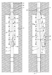
Referring to Figure 1, a main bore 11 has been drilled. At a desired
intersection depth, an enlarged diameter section 13 is created by
underreaming. A
string of main casing 15 has been run into main bore 11 through enlarged
section
13. Enlarged section 13 is created at a desired intersection depth to start a
lateral
branch bore.
A first embodiment of a junction member 17 is connected into main casing
15 at the surface and lowered into enlarged section 13 while running casing
15.
Junction member 17 is in a collapsed position while running in, as shown in
Figure
1. Subsequently, it will be expanded by internal fluid pressure to the set
position in
Figure 2. Junction member 17 is of steel of a high elongation grade which is
capable of being plastically deformed into the collapsed position and expanded
under fluid pressure to the set position.
Junction member 17 includes an upper end section 19 which is secured to a
casing collar 20 of main casing 15. Upper end section 19 is a cylindrical
section
which is coaxial with a main bore axis 23. An upper enlarged section 21 is
joined
to upper end section 19, preferably by welding. Upper enlarged section 21 is a
conical member which diverges or increases in diameter in a downward
direction,
PCT IB/98/01394
CA 02304687 2000-03-28
- 5 -
as can be seen by comparing Figures 6 and 8 and viewing Figures 18 and 19.
Upper enlarged section 21 is a right circular cone generated about an axis 22.
Cone
axis 22 intersects and is inclined at a slight angle relative to main bore
axis 23.
Similarly, a lateral branch axis 25 is inclined slightly and intersects main
bore axis
23 at the same point of intersection as cone axis 22. Cone axis 22 is one-half
the
angle of intersection of lateral axis 25. The angles of intersections may
differ from
well to well, and in the embodiment shown, lateral axis 25 is at a 10 deg.
angle
relative to main axis 23, while cone axis 22 is at a 5 deg. angle. The upper
section
of the lateral branch wellbore (not shown) will be drilled along lateral axis
25.
A lower enlarged conical section 27 joins the lower end of upper enlarged
section 21, such as by welding. Lower enlarged conical section 27 is also a
right
circular cone that is slightly tilted relative to main axis 23. When viewed in
the
elevational view of Figure 2, the left sides of conical upper enlarged section
21 and
lower enlarged section 27 appear flush with each other and in a straight line
with a
i 5 side of main casing 15. Lower enlarged conical section 27 diverges in a
downward
direction, having a decreasing diameter as shown in Figures 18 and 19.
A lateral conical section 29, identical to lower enlarged conical section 27,
also joins upper enlarged section 21, such as by welding. Lateral conical
section 29
is also a section of right circular cone which is tilted relative to main axis
23 and
lateral axis 25. When viewed in the elevational view of Figure 2, a right side
portion of lateral conical section 29 appears flush with a right side section
of upper
enlarged section 21 and parallel to lateral axis 25. Lateral conical section
29 also
diverges in a downward direction, having a decreasing diameter as shown in
Figure
18.
Referring to Figures 17-19, inner side portions of lower enlarged conical
section 27 and lateral conical section 29 are cut or truncated to form a
junction of
the two sections. This junction has a lower perimeter portion 31 that is in a
configuration of a parabola. Lower perimeter portion 31 comprises mating edges
of lower enlarged and lateral conical section 27, 29, the edges being
abuttable with
each other. Lower perimeter portion 31 is contained in a plane that contains
cone
axis 22.
In the first embodiment, a stiffening plate or rib 33 is sandwiched between
the conical lower enlarged and lateral sections 27, 29 at lower perimeter
portion 31.
Stiffening plate 33 is also in the general configuration of a parabola. In the
embodiment shown, it has an inner edge 35 that is in the configuration of a
parabola. Outer edge 37 is also in the configuration of a parabola. However,
the
parabola of inner edge 35 is not as steep, with edges 35, 37 converging toward
each
other in an upward direction. This results in legs 38 for stiffening plate 33
that
decrease in width in an upward direction until reaching a minimum width at
upper
ends 39. Upper ends 39 of stiffening plate 33 are located at the lower end of
upper
enlarged section 21. The width between inner edge 35 and outer edge 37 is the
smallest at this point. The maximum width of plate 33 is at its lowest point.
Stiffening plate 33 is welded to lower enlarged and lateral conical members
27, 29 at junction 31. In this position, inner edge 35 is located above lower
perimeter portion 31, while outer edge 27 is located below lower perimeter
portion
31. Stiffening plate 33 is located in a plane of lower perimeter portion 31.
Conical
PCT IB/98/01394
CA 02304687 2000-03-28
- 6 -
axis 22 passes through a plane containing stiffening plate 33.
The purpose of stiffening plate 33 is to reinforce the junction between lower
enlarged and lateral conical sections 27, 29. Referring to Figures 10 and 12,
internal pressure within junction member 17 will tend to cause junction member
17
to assume a circular configuration. The circular configuration is desired at
the
lower edge of upper enlarged section 21 as shown in Figure 10. However, the
junction of the lower enlarged and lateral conical sections 27, 29 with upper
enlarged section 21 is not circular, as shown in Figure 12. In Figure 12,
which is a
section taken about halfway down the joined lower enlarged and lateral conical
io sections 27, 29, the joined conical sections will have a cross-sectional
configuration
that is not circular. Rather, the distance 40 between outer sides of the lower
enlarged and lateral conical sections 27, 29 perpendicular to a line extending
between legs 38 is substantially greater than the distance between the two
legs 38
of stiffening plate 33 at that point. The cross-section presents a general
peanut
shape, with the dotted lines in Figure 12 representing the full bore access to
the
lower ends of the main and lateral branches. Without stiffening plate 33,
internal
pressure would tend to force the small dimension portion between legs 3 8
apart to
the circular configuration as in Figure 10. This would deform the junction and
restrict the full bore access to both branches. Stiffening plate 33 prevents
such
occurrence at test pressure levels.
Referring again to Figure 2, a cylindrical main section lower end 41 joins
the lower end of lower enlarged conical section 27, which is circular at that
point.
The main section lower end 41 is secured to the lower continuation of main
casing
15 by a threaded collar. Lower end 41 is coaxial with main axis 23. Similarly,
cylindrical lateral end portion 43 joins the lower end of lateral conical
section 29,
which is circular at that point. Lateral section 43 extends downward and
provides a
guide for drilling a lateral branch borehole (not shown). Lateral end section
43 is
coaxial with lateral axis 25. Stiffening plate 33 extends downward a short
distance
between main section lower end 41 and lateral section lower end 43.
Junction member 17 if first constructed and tested in the set configuration,
then will be formed in the collapsed configuration that is shown in Figure 1.
In the
collapsed configuration, the overall diameter is substantially the same as the
diameter of main casing 15 and no greater than the outer diameter of casing
collar
20. Referring to Figure 1 and Figures 3, 5, 7, 9, 11, 13 and 15, the collapsed
configuration has a doubled back section 45 within upper enlarged section 21.
Doubled back section 45 increases in extent in a downward direction as shown
by
comparing Figure 5, Figure 7 and Figure 9.
As shown in Figure 11, lower enlarged conical section 27 remains generally
undeflected. However, lateral conical section 29 is folded into the interior
of lower
enlarged conical section 27. In the position shown, two loops 47 are employed
to
accommodate the full extent. Note that legs 38 will not be in a common plane
in
the collapsed position. In Figure 13, an inner side 49 of main lower end 41 is
doubled back into an outer side section of main lower end 41, presenting a
crescent
shape.
A plurality of axially extending channels 51 are formed in the upper section
of lateral section lower end 43. Stiffening plate 33 is bent into a concave
PCT IB/98/01394
CA 02304687 2000-03-28
- 7 -
configuration at its lower section. Referring to Figure 15, more vertical
channels
51 will be present on lateral section lower end 43, and they will be
symmetrical to
form a corrugated configuration for lateral section lower end 43. The crescent
configuration remains for main section lower end 41 for a short distance
downward
where it again returns to a cylindrical configuration as shown in Figure 1. In
the
collapsed position, lateral end section 43 extends downward generally parallel
with
main axis 23.
In operation, main bore 11 will be drilled, then one or several enlarged
sections 13 are created. The operator inserts one or several junction members
17
into main casing 15 while in the collapsed position and runs main casing 15.
Main
casing 15 will have a conventional cementing shoe (not shown) on its lower
end.
The cement shoe will be of a type which prevents downward flow until a dart or
ball is dropped to shift a valve member. Lateral end 43 has a plug 52 which
seals
both while lateral end 43 is in the corrugated shape and in the set position.
When junction member 17 reaches enlarged bore section 13, the operator
will apply pressure to casing 15. The internal pressure causes junction member
17
to plastically deform from the collapsed position shown in Figure 1 to the set
position shown in Figure 2. The operator then drops a ball or dart to shift
cement
shoe to a position wherein fluid may be pumped downward in main casing 15. The
operator then pumps cement down main casing 15, which flows out the cement
shoe and back up an annulus in main bore 11 surrounding main casing 15. The
cement will flow through the enlarged section 13 and up toward the surface.
Drilling fluid will be pumped down behind the cement to flush main bore casing
15
of cement. A cement wiper plug (not shown) separates the cement from the
drilling fluid, the plug moving downward through junction member 17 to the
lower
end of main bore casing 15.
The operator may then perform further drilling through main casing 15.
When the operator wishes to drill the lateral branch, he will either install a
whipstock in the main borehole or use a kick-out device to deflect the drill
bit over
into the lateral section. The operator drills out plug 52 and continues
drilling at
lateral angle 25 for a selected distance into the earth formation. Once a
desired
depth has been reached for the lateral branch, the operator will run a liner
casing
(not shown). The liner casing will have a conventional hanger and seal for
hanging
and sealing within lateral section lower end 43. The lateral liner casing will
be
cemented in a conventional manner.
Figure 20 illustrates an alternate embodiment in which the walls of the
junction apparatus are formed with multiple plies, each being metal, to
facilitate
expansion from the collapsed position to the set position. For example, Figure
20
shows an inner wall or ply 53 located within an outer ply or wall of conical
members 27' and 29'. The stiffening plate is also formed of multiple plies as
indicated by legs 38'. The total thickness of the two plies should be
substantially
no greater than that of a single wall which has the same pressure rating. The
use of
two walls for the various components of junction member 17 reduces the amount
of strain that would otherwise occur during plastic deformation with a single
wall
having the same total thickness as the two plies.
Figures 21-40 illustrate another embodiment of a junction member, with the
PCT IB/98/01394
CA 02304687 2000-03-28
- 8 -
principal difference between junction member 55 does not use a stiffening
plate
such as stiffening plate 33 (Fig. 2). Referring to Figure 22, junction member
55 has
an upper end section 57 that is cylindrical and of the same diameter as a main
string
of casing (not shown) for attachment to the main string of casing. A conical
upper
enlarged section 59 has an upper end welded to the lower end of upper end
section
57. Upper enlarged section 59 diverges in a downward direction, resulting in a
greater diameter at its lower end at section line 31 than at its upper end
above
section line 25. Upper enlarged section 59 has an axis 61 which is inclined
relative
to main casing axis 63.
lo A conical lower enlarged section 65 has an upper end welded to part of the
lower end of upper enlarged section 59. Conical lower enlarged section 65 is
much
shorter in length than the length of upper enlarged section 59. Conical
section 65
converges in a downward direction, as can be seen by comparing Figures 33 and
35, and comprises one-half of a cone with a diameter at its lower end that is
substantially the same as the diameter of the upper end section 57.
A conical lateral section 67 also joins the lower end of upper enlarged
section 59. Conical lateral section 67 is the same length as conical lower
enlarged
section 65, but of a lesser diameter. Referring to Figure 33, conical lateral
section
67 forms the right half of junction member 55 at section line 33, with conical
lower
enlarged section 65 forming the left half at that point. Conical lower
enlarged
section 65 and lateral section 67 are truncated and abutted along their inner
edges
68, the inner edges 68 being in a plane which contains axis 61 of upper
enlarged
section. Inner edges 68 of the conical lower enlarged section 65 and conical
lateral
section 67 are welded together.
In the first embodiment, a stiffening plate 33 is located between the inner
edges, while in this embodiment, it is not required due to the relatively
short
lengths of conical lower enlarged and lateral sections 65, 67. As shown in
Figure
33, the shape of junction member 55 at that point is somewhat in the shape of
a
peanut, with a major dimension 69 that is greater than a minor dimension
measured
perpendicular to line 69 at the midpoint of line 69.
Referring again to Figure 22, a lower main section 71 of cylindrical
configuration is welded to the lower end of conical lower enlarged section 65.
Lower main section 71 joins main casing (not shown) extending below and is
coaxial with upper main section 57 and main axis 63. A lower lateral section
73 of
cylindrical configuration is welded to the lower end of conical lateral
section 67.
Lower lateral section 73 will receive a string of lateral liner (not shown).
Junction
member 55 while in the expanded position resembles an inverted "Y". A
drillable
plug 75 is secured in lower lateral section 73. The diameter of lower lateral
section
73 is smaller than the diameter of lower main section 71. Lower lateral
section 73
is located on a lateral branch axis 77 which is at an acute angle relative to
main
casing axis 63. Upper enlarged section axis 61 bisects axes 63 and 77, with
all
three axes 61, 63, 77 being in a single plane.
For manufacturing purposes, a segmented rod 79 is secured to junction
apparatus 55. Segmented rod 79 has two portions 79a, 79b, each located on the
exterior of junction member 55 180 deg. apart from the other. Segmented rod
portions 79a, 79b are identical and are used when deforming junction member 55
PCT IB/98/01394
CA 02304687 2000-03-28
- 9 -
from the set position of Figure 22 to the collapsed position of Figure 21, as
will be
subsequently explained. Figure 23 shows segmented rod 79 prior to
installation.
Each segmented rod portion 79a, 79b has an upper end 81 which is tack welded
to
exterior portion of junction member 55 near the upper end of upper enlarged
section 59. The middle section 83 of segmented rod 79 loops under the lower
end
of the intersection of the conical lower enlarged section 65 and conical
lateral
section 67. Each segmented rod portion 79a, 79b is located in a plane that
contains
upper enlarged section axis 61.
Junction member 55 will first be formed and tested in the expanded
configuration of Figure 22 or in the folded configuration of Figure 39 with
some
external support. Then it will be collapsed to the position shown in Figure 21
for
passage into the well. Referring to Figures 38 and 40, in the first step,
junction
member 55 will be positioned on a folding machine 90 which extends from the
lower end of lower lateral section 73 to upper end section 57 (Fig. 22).
Folding
machine 90 has two opposed convex, blunt blades 91, 93. Blades 91 are hinged
together by a hinge 92 at the end near upper end section 57. Folding machine
90
has two stationary retainers or supports 87, 89. Figures 38 and 39 are taken
at a
section similar to the section shown in Figures 30 and 31.
For reference, assume that blades 91, 93 are at the 0 deg. and 180 deg.
position, while retainers 87, 89 are stationarily mounted at the 90 deg. and
270 deg.
position. The lateral leg or lower lateral section 73 will be located at the
90 deg.
position and held in place by stationary support 87. Then, blades 91, 93 are
moved
toward each other by hydraulic force until a point on the inner diameter at
the 0
deg. position contacts a point on the inner diameter at the 180 deg. position.
This
step folds junction member 55 into two halves, forming two concave bights 94.
Note by comparing Figures 24, 26, 28 and 30, that blades 91, 93 do not form
bights
94 of constant depth. The distance between blades 91, 93 at hinge 92 and the
conical configuration of junction member 55 creates shallower bights 94 at the
upper end, with the inner sides of junction member 55 touching only in the
proximity of section line 31 (Fig. 22).
Then, as shown in Figure 41, segmented rod 79 is secured in the bights 94,
with the middle portion 83 looped between lower lateral sections 73 and lower
main section 71. The upper ends 81 will be tack welded in the bights 94. As
shown in Figures 26, 28 and 30, the distance between segmented rod portions
79a,
79b gradually increases in the upward direction from the lower end of upper
enlarged section 59 to the upper ends 81 generally at section line 26 (Fig
26).
Returning to Figures 41 and 43, junction member 55 is then placed in a
collapsing machine 96. Collapsing machine 96 has two concave dies 95, 97 which
are semicylindrical, forming a cylinder when brought together as in Figure 42.
The
inner diameter of dies 95, 97 is substantially the same as the outer diameter
of
upper end section 19 collar 20 (Fig. 1). Concave dies 95, 97 are located at
the 90
deg. and 270 deg. position and connected by a hinge 98 at the upper end as
shown
in Figure 43. Figures 41, 42 are also shown at a section line at the lower end
of
upper enlarged section 59, this section line being shown in Figure 30.
Die 95 is hydraulically moved toward die 97, causing the two lobes
opposite bights 94 to collapse into configuration shown in Figure 42. In this
PCT IB/98/01394
CA 02304687 2000-03-28
- 10 -
configuration, junction member 55 has an outer diameter, or cylindrical
surface of
revolution, which is no greater than collar 20 of upper end section 57 or 19.
As
can be seen in Figures 32 and 34, die 95 folds lower lateral section 73 inward
into a
concave depression formed in lower main section 71. Lower main section 71 will
be crescent-shaped, while lower lateral section 73 remains mostly cylindrical
and
substantially undeflected. As shown by dotted lines 99 in Figure 36, the
surface of
revolution of junction member 55 is cylindrical and no greater at any point
than the
outer diameter of collar 20 (Fig. 1). Segmented rod portions 79a, 79b limit
strain
during the bending of bights 94, preventing them from forming curved portions
which are too small in radius.
Junction apparatus 55 is run and installed in the same manner as described
in connection with the first embodiment. It is run in while in the collapsed
position
of Figure 21. Junction member 55 will locate within a reamed out section of
the
borehole. Hydraulic pressure is supplied to liquid contained in the main
casing and
junction apparatus 59. A plug (not shown) at the cement shoe at the lower end
of
the main casing enables hydraulic pressure to be applied throughout the length
of
casing and junction apparatus 55. The pressure causes junction member 55 to
expand to the set position with lateral leg 73 moving outward.
After reaching this position, a valve will be shifted at the cement shoe to
enable cement to be pumped downward, which flows through the main casing and
back up at annulus surrounding the main casing. When it is desired to drill
the
lateral well bore, the operator uses a kick-off tool or whipstock to cause bit
to enter
lateral leg 73, drill-out plug 75 and drill the lateral leg. Lateral casing of
smaller
diameter than the main casing will be run through lateral leg 73 and supported
by a
hanger mechanism in lateral leg 73. Lateral casing will be cemented
conventionally.
The invention has significant advantages. The junction apparatus provides
a good seal between the main casing and the lateral branch casing. The
junction
member may be run in collapsed and expanded to a set position. The method of
running the junction member in with the main casing avoids a need to mill out
a
window or section of the main casing. In the second embodiment, there is not
need
to plastically deflect greatly the cylindrical part of the lateral leg,
facilitating a plug
to be located therein.
While the invention has been shown in only one of its forms, it should be
apparent to those skilled in the art that it is not so limited, but is
susceptible to
various changes without departing from the scope of the invention. For
instance
the conical sections can be replaced by an extended stiffening plate. Also the
bottom of upper enlarged section 21 can be large enough to accommodate full
access to both branches side by side, and the stiffening plate inner edge 35
can be
straight without any legs 38.
PCT IB/98/01394