Note: Descriptions are shown in the official language in which they were submitted.
CA 02304966 2004-04-29
BI-CENTER BIT ADAPTED TO DRILL CASING SHOE
BACKGROUND OF THE INVENTION
1. Field of the Invention
The present invention is directed to downhole tools. More
specifically, the present invention is directed to a bi-center
drilling bit adapted to fit within the drill through a casing shoe
without damage to the surrounding casing.
2. Background
Bi-center bits are adapted for insertion down a wellbore having a
given diameter where, once in position, the rotation of the bi-center
bit creates a borehole having a selectedly greater diameter than the
borehole.
In conventional bi-center bits, the bit is designed to rotate
about a rotational axis which generally corresponds to the rotational
axis defined by the drill string. Such conventional designs are
further provided with cutting elements positioned about the face of
the tool to reveal a low backrake angle so as to provide maximum
cutting efficiency.
Disadvantages of such conventional bi-center bits lie in their
inability to operate as a cutting tool within their pass-through
diameter while still retaining the ability to function as a
traditional bi-center bit. In such a fashion, a conventional bi-
center bit which is operated within casing of its pass-through
diameter will substantially damage, if not destroy the casing.
SUMMARY OF THE INVENTION
The present invention addresses the above and other disadvantages
1
CA 02304966 2004-04-29
of prior bi-center drilling bits by allowing selective modification of
the use of the tool within the borehole.
In one embodiment, the present invention includes a drill bit
body which defines a pilot section, a reamer section and a geometric
axis. The pilot section defines a typical cutting surface about which
is disposed a plurality of cutting elements. These elements are
situated about the cutting face to generally define a second
rotational axis separate from the rotational axis defined by the drill
string as a whole. This second or pass-through axis is formed by the
rotation of the bit about the pass-through diameter.
In one embodiment, the pilot section may define a smaller
diametrical cross-section so as to further prevent the possibility of
damage to the borehole and/or casing when the bit is rotated about the
pass-through axis. To further accomplish this goal, a gauge pad may
also be situated on the drill bit body opposite the
la
CA 02304966 2001-04-27
reamer. In yet other embodiments, cutters emphasizing a high back rake angle
are employed on the peripheral
cutting blades of the tool.
The present invention presents a number of advantages over prior art bi-center
bits. One such
advantage is the ability of the bi-center bit to operate within a borehole or
casing approximating its pass-
through diameter without damaging the borehole or casing. In the instance of
use in casing, the casing shoe
may thus be drilled through.
A second advantage is the ability of the same tool to be used as a
conventional bi-center bit to create
a borehole having a diameter greater than its pass-through diameter. In such a
fashion, considerable cost
savings may be observed since only one tool need be used where this tool need
not be retrieved to the surface
I 0 to modify its character of use.
Other advantages ofthe invention will become obvious to those skilled in the
art in light of the figures
and the detailed description of the preferred embodiments.
BRIEF DESCRIPTION OF THE DRAWINGS
Figure 1 is a side view of a conventional bi-center drill bit; F~ figure 2 is
an end view of the working
face ofthe bi-center drill bit illustrated in Figure l;
Figures 3A-C are end views of a bi-center bit as positioned in a borehole
illustrating the pilot bit
diameter, the drill hole diameter and pass through diameter, respectively;
Figures 4A-B illustrate a conventional side view of a bi-center bit as it may
be situated in casing and
in operation, respectively;
Figure 5 is an end view of a conventional bi-center bit;
Figure 6 illustrates a cutting structure brazed in place within a pocket
milled into a rib of a
conventional bi-center drill bit;
Figure 7 illustrates a schematic outline view of an exemplary bi-center bit of
the prior art;
Figure 8 illustrates a revolved section of a conventional pilot .section
cutter coverage as drawn about
the geometric axis;
Figure 9 illustrates a revolved section of a conventional pilot section cutter
coverage as drawn about
the pass-through axis;
Figure 10 illustrates a side view of one embodiment of the bi-center bit of
the present invention;
Figure 11 illustrates an end view of the bi-center bit illustrated in Figure
10;
Figure 12 illustrates a revolved section of the pilot section of the bi-center
bit illustrated in Figure 10,
as drawn through the pass-through axis;
Figure 13 illustrates a revolved section of the pilot section of the bi-center
bit illustrated in Figure 10,
2
CA 02304966 2001-04-27
as drawn through the geometric axis;
Figure 14 illustrates a graphic profile of the cutters positioned on the
reamer section of the
embodiment illustrated in Figure 10.
Figure 15 illustrates a schematic view of the orientation of cutters in one
preferred embodiment of
the invention.
While the present invention will be described in connection with presently
preferred embodiments,
it will be understood that it is not intended to limit the invention to those
embodiments. On the contrary, it
is intended to cover all alternatives, modifications, and equivalents included
within the spirit of the invention
and as defined in the appended claims.
DESCRIPTION OF THE PREFERRED EMBODIMENTS
Figures 1-9 generally illustrate a conventional bi-center bi,t and its method
of operating in the
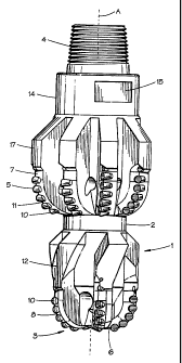
borehole.
By reference to these figures, bit body 2, manufactured fronn steel or other
hard metal, includes a
threaded pin 4 at one end for connection in the drill string, and a pilot bit
3 defining an operating end face 6
at its opposite end. A reamer section 5 is integrally formed with the body 2
between the pin 4 and the pilot
bit 3 and defines a second operating end face 7, as illustrated. The term
"operating end face" as used herein
includes not only the axial end or axially facing portion shown in Figure 2,
but also contiguous areas
extending up along the lower sides of the bit 1 and reamer 5. The operating
end face 6 of bit 3 is traversed by
a number of upsets in the form of ribs or blades 8 radiating from t:he lower
central area of the bit 3 and
extending across the underside and up along the lower side surfaces of said
bit 3. Ribs 8 carry cutting
members 10, as more fully described below. Just above the upper ends of rib 8,
bit 3 defines a gauge or
stabilizer section, including stabilizer ribs or gauge pads 12, each of which
is continuous with a respective one
of the cutter carrying rib 8. Ribs 8 contact the walls of the borehole that
has been drilled by operating end face
6 to centralize and stabilize the tool l and to help control its vibration.
(See Figure 4).
The pass-through diameter of the bi-center is defined by the three points
where the cutting blades are
at gauge. These three points are illustrated at Figure 2 are designatc;d "x",
"y" and "z". Reamer section 5
includes two or more blades 11 which are eccentrically positioned above the
pilot bit 3 in a manner best
illustrated in Figure 2. Blades 11 also carry cutting elements 10 as described
below. Blades 11 radiate from
the tool axis but are only positioned about a selected portion or quadrant of
the tool when viewed in end cross
section. In such a fashion, the tool 1 may be tripped into a hole having a
diameter marginally greater than the
maximum diameter drawn through the reamer section 5, yet be able to cut a
drill hole of substantially greater
diameter than the pass-through diameter when the tool 1 is rotated about the
geometric or rotational axis "A".
3
CA 02304966 2001-04-27
The axis defined by the pass-through diameter is identified at ''B". (S~
Figures 4A-B.)
In the conventional embodiment illustrated in Figure l, cutting elements 10
are positioned about the
operating end face 7 of the reamer section 5. Just above the upper ends of rib
11, reamer section S defines
a gauge or stabilizer section, including stabilizer ribs or kickers 1 T, each
of which is continuous with a
S respective one of the cutter carrying rib 11. Ribs 11 contact the walls of
the borehole that has been drilled by
operating end face 7 to further centralize and stabilize the tool l and to
help control its vibration.
Intermediate stabilizer section defined by ribs 11 and pin 4 is a shank 14
having wrench flats 15 that
may be engaged to make up and break out the tool 1 from the drill string (not
illustrated). By reference again
to Figure 2, the underside of the bit body 2 has a number of cireuiation ports
or nozzles 15 located near its
centerline. Nozzles 15 communicate with the inset areas between ribs 8 and 11,
which areas serve as fluid
flow spaces in use. With reference now to Figures l and 2, bit body 2 i<.~
intended to be rotated in the clockwise
direction, when viewed downwardly, about axis "A". Thus, each of the ribs 8
and 11 has a leading edge
surface 8A and 1 lA and a trailing edge surface 8B and 11B, respectively. As
shown in Figure 6, each of the
cutting members 10 is preferably comprised of a mounting body 20 comprised of
sintered tungsten carbide
l~ or some other suitable material, and a layer 22 of polycrystalline diamond
earned on the leading face of stud
38 and defining the cutting face 30A of the cutting member. The cutting
members 10 are mounted in the
respective ribs 8 and 11 so that their cutting faces are exposed through the
leading edge surfaces 8A and 1 l,
respectively.
In the conventional bi-center bit illustrated in Figures 1-9, cutting members
10 are mounted so as to
position the cutter face 30A at an aggressive, low angle, e.g., 15-20°
b~ackrake, with respect to the formation.
This is especially true of the cutting members 10 positioned at the leading
edges of bit body 2. Ribs 8 and
11 are themselves preferably comprised of steel or some other hard metal. The
tungsten carbide cutter body
38 is preferably brazed into a pocket 32 and includes within the pocket the
excess braze material 29.
As illustrated in profile in Figure 7, the conventional bi-center bit normally
includes a pilot section
3 which defines an outside diameter at least equal to the diameter of bit body
2. In such a fashion, cutters on
pilot section 3 may cut to gauge. The cutter coverage of a conventional bi-
center bit may be viewed by
reference to a section rotated about a given axis. Figure 8 illustrates the
cutter coverage for the pilot bit
illustrated in Figures 1-2. The revolved section identifies moderate to
extreme coverage overlap of the cutters,
with the maximum overlap occurring at the crown or bottommost extent of pilot
section 3 when said pilot
section 3 is rotated about geometric axis "A". The cutter coverage illustrated
iii Figure 8 should be compared
with the absence of cutter coverage occurring when pilot section 3 is rotated
about the pass-through axis "B"
(See Fig. 9.). Clearly, the bi-center bit illustrated in Figure 9 would be
inefficient if used in hard or resilient
formations such as a casing shoe.
4
CA 02304966 2001-04-27
When a conventional bi-center bit is rotated about its rotational axis "A" the
bit performs in the
manner earlier described to create a borehole having a diameter largE;r than
its pass-through diameter. (See
Figs. 4A-4B.). This result is not desirable when the bit is used in casing to
drill through a casing shoe since,
while the shoe might be removed, the casing above the shoe would also be
damaged. Consequently, it has
become accepted practice to drill through a casing shoe using a conventional
drill bit which is thereafter
retrieved to the surface. A bi-center bit is then run below the casing to
enlarge the borehole. However, the
aforedescribed procedure is costly, especially in deep wells when many
thousand feet of drill pipe may need
be tripped out of the well to replace the conventional drilling bit with the
bi-center bit. The bi-center bit of
the present invention addresses this issue.
One embodiment of the bi-center bit of the present invention may be seen by
reference to Figures 10-
15. Figure 10 illustrates a side view of a preferred embodiment of the bi-
center bit of the present invention.
By reference to the figures, the bit 100 comprises a bit body 102 which
includes a threaded pin at one end
104 for connection to a drill string and a pilot bit 103 defining an operating
end face 106 at its opposite end.
For reasons discussed below, end face 106 defines a flattened profile. A
reamer section 105 is integrally
formed with body 102 between the pin 104 and pilot bit 103 and defme;s a
second operating end face 107. The
operating end face 106 of pilot 103 is traversed by a number of upsets in the
form of ribs and blades 108
radiating from the central area of bit 103. As in the conventional embodiment,
ribs 108 carry a plurality of
cutting members 110. The reamer section 105 is also provided with a number of
blades or upsets 152, which
upsets are also provided with a plurality of cutting elements 110 which
themselves define cutting faces 130A.
The embodiment illustrated in Figure 10 is provided with a pilot section 103
defining a smaller cross-section
of diameter than the conventional embodiment illustrated in Figures 1-8. The
use of a lesser diameter for pilot
section 103 serves to minimize the opportunity for damage to the borehole or
casing when the tool 100 is
rotated about the pass-through axis "B".
In a conventional bit, cutters 110 which extend to gauge generally include a
low backrake angle for
maximum efficiency in cutting. (See Figure 11.). In the bi-center bit of the
present invention, it is desirable
to utilize cutting elements which define a less aggressive cutter posture
where they extend to gauge when
rotating about the pass-through axis. In this connection, it is desirable that
cutters 110 at the pass-through
gauge and positioned on the leading and trailing blades 118 define a backrake
angle of between 30-90 degrees
with the formation. Applicant has discovered that a preferred backral~e angle
for soft to medium formations
is 55 degrees. The orientation of cutting elements 100 to define such high
backrake angles further reduces
the potential for damage to casing 136 when the tool 110 is rotated about the
pass-through axis "B".
In a preferred embodiment, bit 100 may be provided with a stalbilizer pad 160
opposite reamer section
105. Pad 160 may be secured to bit body 102 in a conventional fashion, e.g.,
welding, or may be formed
integrally. Pad 160 serves to define the outer diametrical extent of tool 100
opposite pilot 103. (See Figure
10.) It is desirable that the uppermost extent 161 of pad 160 not exl:end
beyond the top of cutters 121 on
CA 02304966 2001-04-27
reamer blades 132. When rotated in the casing, the tool 100 is compelled to
rotate about pass-through axis
"B" due to the physical constraints of casing 136. Casing 136 is not cut since
contact with tool 100 is about
the three points defined by leading edges 118 and stabilizer pad 160. As set
forth above, edges 118 include
cutting elements having a high backrake angle not suited to cut casing; 136.
Likewise, pad 160 is not adapted
to cut casing 136. The cutters disposed elsewhere about operating face 107
incorporate a backrake angle of
15°-30° and thus are able to cut through the casing shoe. When
the easing shoe has been cut, the tool 100 is
able to rotate free of the physical restraints imposed by casing 136. In such
an environment, the tool reverts
to rotation about axis "A".
The method by which the bi-center bit of the present invention may be
constructed may be described
as follows. In an exemplary bi-center bit, a cutter profile is established for
the pilot bit . Such a profile is
illustrated, for example, in Figure 8 as drawn through the geometrical axis of
the tool. The pass-through axis
is then determined from the size and shape of the tool.
Once the pass-through diameter is determined, a cutter profiile of the tool is
made about the pass-
through axis. This profile will identify any necessary movement of cutters 110
to cover any open, uncovered
regions on the cutter profile. These cutters 110 may be situated along the
primary upset 131 or upsets 132
radially disposed about geometric axis "A".
Once positioning of the cutters 110 has been determined, the position of the
upsets themselves must
be established. In the example where it has been determined that a cutler 110
must be positioned at a sel~ted
distance rl, from pass-through axis "B" an arc 49 is drawn through rl in the
manner illustrated in Figure 15.
The intersection of this arc 49 and a line drawn through axis "A" determines
the possible positions of cutter
110 on radially disposed upsets 151.
To create a workable cutter profile for a bi-center bit which imcludes a
highly tapered or contoured
bit face introduces complexity into the placement of said cutters 110 svzce
issues of both placement and cutter
height must be addressed. As a result, it has been found preferable to utilize
a bit face which is substantially
flattened in cross section. (See Figure 10.). Once positioning of the upsets
has been determined, the cutters
110 must be oriented in a fashion to optimize their use when tool 100 is
rotated about both the pass-through
axis "B" and geometric axis "A". By reference to Figures 11 and 1:5, cutters
110 positioned for use in a
conventional bi-center bit will be oriented with their cutting surfaces
oriented toward the surface to the cut,
e.g., the formation. In a conventional bi-center bit, however, cutters 11 ~D
so oriented an the primary upset 131
in the area 140 between axes ''A" and "B" will actually be oriented 1801 to
the direction of cut when tool 100
is rotated about pass-through axis "B". To address this issue, it is
preferable that at least most of cutters 110
situated on primary upset 131 about area 140 be oppositely oriented such that
their cutting faces 130A are
brought into contact with the formation or the casing shoe, as the case rnay
be, when tool 100 is rotated about
axis "B". This opposite orientation of cutter I 10 is in deference to the
resilient compounds often comprising
the casing shoe.
6
CA 02304966 2001-04-27
Cutters 110 disposed along primary upset 131 outside of region 140 in region
141 are oriented such
that their cutting faces 130A are brought into at least partial contact with
the formation regardless when
rotated about axis "A". Cutters 110 oppositely disposed about prim~uy upset
131 in region 142 are oriented
in a conventional fashion. (See Figure 15.)
Cutters 110 not situated on primary upset 131 oriented are disposed on radial
upsets 132. These
cutters 110, while their positioning may be dictated by the necessity for
cutter coverage when tool 100 is
rotated about axes "A" and "B" as described above, are oriented on their
respective upsets 132 or are skewed
to such an angle such that at least twenty percent of the active cutter face
130 engages the formation when the
bi-center bit is rotated about axis "A". Restated as a function of direction
of cut, the skew angle of cutters 110
is from 0°-80°.
7