Note: Descriptions are shown in the official language in which they were submitted.
CA 02305285 2000-03-28
WO 99/26446 PCTNS98I24560
-1-
The present invention relates to techniques and devices for scheduling
available bit rate
(ABR) traffic over an asynchronous transfer mode (ATM) link, in such a manner
as to provide
a virtual circuit with ABR service having a specified minimum cell rate (MCR)
that may be
greater than zero.
Background Art
Modern society is increasingly dependent on the ability to communicate
information.
More and more applications require communications of varying quantities of
information between
users. The trend in communications technology is to develop packet or cell
based systems for
communications transport and switching at ever higher speeds.
Increasing demands for many communication services, having different
requirements,
drove the development of separate networks. For example, analog voice
telephone services
utilize a complex network of voice traffic switches, lines and trunks to
provide ubiquitous
switched voice connectivity virtually throughout the world. The modern
telephone network
carries most voice traffic in digitized form, typically using time division
multiplexing techniques.
2o The switched voice network can carry some data traffic, using moderns or
ISDN interfaces.
However, the telephone network cannot readily switch higher speed data
traffic, therefore a
variety of separate data networks evolved. Examples of such data networks
include X.25, frame
relay and SMDS. The construction, operation, maintenance and upgrading of such
disparate
networks for different services are increasingly complex and expensive,
particularly as traffic
demands continue to increase.
Asynchronous transfer mode (ATM) transport, an advanced, high-speed packet
switching
technology, has emerged as the latest form of packet or cell based switching.
ATM promises fast
cell switching for wide ranges of traffic demands. ATM is intended to carry
virtually any type
of information that can be expressed in or converted to digital form, from
voice telephone traffic,
3o to real-time video, to high-speed file transfers, to faster than real-time
video, etc. ATM based
networks are eliminating the need for different networks to carry different
types of traffic. In
ATM, transfer is asynchronous in the sense that the recurrence of cells that
contain information
CA 02305285 2000-03-28
WO 99126446 PCTIUS98I24560
-2-
from any particular sender is not necessarily periodic. Each device using the
ATM network
submits a cell for transfer when it has a cell to send. Once aggregated and
scheduled, the ATM
cells ride in synchronous slots on a high-speed media, such as a SONET optical
fiber.
In ATM, information is organized into cells having a fixed length and format.
Each cell
includes a header, primarily for identifying cells relating to the same
virtual connection, and an
information field or "payload". The ATM standard defines a cell size of 53
bytes or octets. The
first five bytes of each cell form the header, and the remaining 48 bytes
represent payload data.
The header of each cell includes a field for a virtual path identifier (VPI)
and a virtual circuit
identifier (VCI). The VPI and VCI together identify the particular circuit or
communication to
which each cell relates.
Within a transport stream, the VPI and VCI identifiers serve to divide the
stream into
separate logical or 'virtual' paths and to segregate traffic within each
virtual path into logical or
'virtual' circuits. An ATM transport device makes the virtual circuit
connections, within one or
more virtual path connections, available to transport any number of individual
communications
over the link. Such logical circuit connections are set up and torn down, as
needed, to efficiently
provide required transport capacity for independent communication sessions to
and from a
number of separate communication devices.
Different types of communication require different transport rates. Also,
different
communications require different levels of service quality, sometimes referred
to as quality of
2o service or QoS. For example, real-time video transmission requires a high
constant bit rate to
maintain synchronism, whereas packet data communications do not. At the
network speeds now
available for ATM transport, voice communication becomes a bursty data traffic
service. To
provide these different levels of service, an ATM link typically will support
a number of different
types of traffic.
The specification for ATM transport defines five traffic or service categories
supported
by the ATM layer of the network, most notably including constant bit rate
(CBR) service,
variable bit rate (VBR) service and available bit rate service. CBR service
provides a constant.
guaranteed bandwidth over an assigned virtual circuit. VBR provides some
maximum number
of transmit opportunities, which may or may not be used to transmit cells over
the associated
3o virtual circuit, for example far bursty tragic. Over time, the actual rate
or bandwidth may vary
from almost zero (little or no use of the opportunities to send) up to the
amount provided by the
maximum number of transmit opportunities (full use) allocated for the circuit.
With ABR service,
CA 02305285 2000-03-28
' ' . , : ' , ~ -,~ ,.,-.. ,
_3_ _ , ~ ~ . '' °
n ~ '~~o 00
., ., ., -. , . . . . o n a a a r a a a a
a data communication device may have an opportunity to transmit in time slots
that are available
because the time slots were not used by CBR or VBR services.
For ABR service, the specification for ATM defines an allowed cell rate (ACR)
and a
minimum cell rate (MCR). The allowed cell rate is the bandwidth, in terms of
cells per second,
currently usable by a particular ABR connection. Typically, the ACR for an ABR
connection
varies over time, for example as a function of the traffic load on the ATM
link. The minimum
cell rate is the lowest bandwidth that the connection is always guaranteed.
The MCR may be zero, and if so, then the device regulating traffic need not
reserve any
bandwidth for the ABR connection. The scheduling device only needs to make a
'best effort' to
provide bandwidth, unused by other connections, for use by the ABR connection.
The device
can, if necessary, allocate all transmit opportunities to higher priority
traffic, in which case, the
ACR for the ABR circuit falls to zero.
However, if the ABR connection has an MCR value greater than zero, then the
scheduling device effectively must reserve some minimum number of cell
transmit opportunities
for that connection, to support traffic for that connection at no less than
the MICR rate. The
device can not allocate all transmit opportunities to other circuits and
services. In existing ATM
systems, there is no scheduling mechanism available, which can dynamically
schedule traffic for
ABR service and guarantee non-zero minimum cell rates for the ABR connections.
In U.S. Pat. 5,619,502. Kahn and Eckhardt disclose a communication subsystem
that
includes a static scheduler and a dynamic scheduler. The static scheduler
accesses a scheduling
list that specifies either a virtual circuit or a dynamic scheduling
indication for each cell slot on a
communication link. The static scheduler selects the virtual circuit specified
by the scheduling
list if the scheduling list specifies the virtual circuit for the cell slot
and the dynamic scheduler
selects a virtual circuit from a dynamic scheduling list for transfer of the
outbound
communication cell if the scheduling list specifies the dynamic scheduling
indication for the cell
slot. The communication subsystem also includes a counter that counts if an
idle communication
cell is transferred over the communication link due to an underrun such that
the virtual circuit
specified by the dynamic scheduling list is skipped if the counter indicates
the underrun.
In GB Application GB 2,307,823A, Jones discloses a method of controlling the
flow of
cells on an ABR connection at a buffering point in an ATM network switch using
a traffic
A~~~ SHEET
CA 02305285 2000-03-28
., _. . _. .. _. ..; ._, ,;
. , n ., . . ' i . . 7 ~ i ', '~ . ~. U
'] n .. . ~ _, .7 n n O n
a , _ 3A _ . , n n a o n ,, ~ o ~_
,. . , n n o 0
~, , .,-,.., ., . . n.an aao ee ee
shaping process to guarantee a minimum cell rate for the ABR VC, preferably in
combination
with arbitration means to ensure a fair distribution of bandwidth through all
the VCs on the
switch. Jones also discloses an ATM network switch that includes cell
buffering means with
traffic shaping means for guaranteeing a minimum cell rate for each ABR VC
configured on the
switch, and arbitration means for ensuring a fair distribution of bandwidth
through all the VCs on
the switch.
In U.S. Pat. 5,392,280, Zheng discloses a connection-oriented packet or cell
switching
networks. A data transmission system and a scheduling protocol utilize both
synchronous
transmission and asynchronous transmission in an alternating pattern to
provide each user with
both a guaranteed transmission bandwidth or capacity to accommodate real-time
communications, and bandwidth sharing among users to increase network
utilization, while
simultaneously eliminating network congestion to avoid data losses. The
synchronous time slots
provide for the bandwidth guarantees, while the asynchronous time slots are
used to transmit
data when a part of a previous synchronous time slot is not used. The
asynchronous time slots
also permit asynchronous data transmission using unallocated time within a
given time frame.
Time frames for data transmission are composed of synchronous transmission
times interspersed
with asynchronous transmission times. For a given time frame, alternating
synchronous and
asynchronous transmission times are specified by a controller which determines
the pattern of
this alternation. The pattern is altered uslllg novel timed-round-robin
scheduling which transmits
cells df data of respective connections over an outgoing link depending upon
the synchronous
transmission time allocated to each connection. To avoid data losses,
asynchronous transmission
is permitted only when a downstream switch indicates sufficient buffer space
to accommodate
asynchronous transmission from an upstream switch.
In U.S. Pat. 5,515,363, Ben-Nun discloses a system for controlling the
transmission of
cells from a network node over multiple Virtual Circuits (VCs). The system
performs traffic
shaping, as required by connection based systems such as Asynchronous Transfer
Mode (ATM),
for each VC connected with a network node, so that the Quality of Service
(Qos) parameters
established when the connection was established are not eYCeeded. The system
includes a
process for scheduling the transmission of cells from the network node. The
scheduling process
periodically scans a table having entries corresponding to virtual circuits
connected with the
network node. During each scan of the table, the scheduler increments a
sustainable rate
accumulator field, a peak rate accumulator field, and a latency accumulator
field of each table
entry that corresponds with a virtual circuit that is open, and for which
there is cell ready to be
~";;~~~ s~~
CA 02305285 2000-03-28
_ , _. _.
;, , . .. ,;
n n . . s ,
- .~B ' ' ~ .i , ~ o . . ~ ~ A o ~=
7 ~ . .~ n .z
.. n n i ,, . . o . n :~ n n 7 1 n 'f n A
transmitted. The scheduler further determines if the sustainable rate
accumulator value is greater
thaw or equal to a predetermined value and whether the peak rate accumulator
value is greater
than or equal to a predetermined value. If both conditions are true, then a
cell may be
transmitted on the virtual circuit corresponding with that table entry. The
system further
provides that transmissions are scheduled on virtual circuits having the
greatest latency since
previous transmissions.
An ATM segmentation and reassembly circuit sold by Digital Equipment
Corporation
under the name AToM3 provided a VBR service within a minimum cell rate, but
not an ABR
service with a minimum cell rate. The AToM3 used a static scheduling table to
support constant
bit rate traffic and variable bit rate traffic. The lines of the static table,
indexed by cell transmit
time, contained fields for high priority service and low priority service. The
scheduler in the
AToM3 provided a guaranteed transmit opportunity for a virtual circuit
connection identified in
the high priority field, to provide CBR service for that circuit. In a cell
transmit time, if the
scheduler identified a VCC in the high priority field for a particular time
slot, a cell was
transmitted for that VCC in the time slot. The scheduler used the low priority
fields for variable
bit rate services. In any cell transmit time when there was no high priority
cell transmission
scheduled, the scheduler looked to the low priority field and offered the
transmit opportunity to
the VCC identified in that field. A cell was transmitted for the low priority
VCC if that VCC had
a cell ready for transmission.
~~;y~oso s~EE~c
CA 02305285 2000-03-28
WO 99/26446 PCT/US9$124560
-4-
The AToM3 supported the minimum bit rate guarantee for VBR service by using
identifiers for the same VBR type VCC in the high priority field and the low
priority field, in
different lines of the static scheduling table. When the scheduler found the
VCC in the high-
priority field in one line of the table, the scheduler scheduled the cell
transmission for that VCC
during each cell transmit time that indexed that line of the static table,
just as if the scheduler were
providing a CBR service. Appearances of the VCC identifier in the low priority
f eld of a number
of lines provided additional bandwidth in the form of a variable bit rate
portion of the service for
the particular VCC.
In this manner, the AToM3 scheduler provided CBR service, VBR service and VBR
l0 service with a guaranteed minimum cell transmission rate. ABR type service
requires dynamic
scheduling. Although dynamic scheduling for ABR service is separately known,
the static
scheduling used in the AToM3, did not support ABR service and was not readily
adaptable to
ABR service. As discussed earlier, the known examples of dynamic scheduling
for ABR services
do not support an MCR value that is greater than zero. Consequently, a need
still exists for a
scheduling methodology and actual ATM transport devices that can deliver ABR
service with a
non-zero guaranteed minimum cell rate.
Disclosure of the Invention
The present invention solves the above discussed problem by using a
combination of static
scheduling and dynamic scheduling of ATM cell transmit opportunities, to
provide ABR transport
with a minimum cell rate greater than zero. An ATM scheduler in accord with
the invention
statically schedules some non-zero cell transmit opportunities for the ABR
virtual circuit, as if
the circuit had a high priority service, similar to CBR service. This provides
the guaranteed
minimum cell rate. Other transmit opportunities are provided to the same
virtual circuit, when
transmit times are available because they were not used for other virtual
circuits.
Thus, in one aspect, the present invention relates to a method of scheduling
asynchronous
transfer mode (ATM) cell traffic for transmission over a link, for available
bit rate service. The
method includes steps of statically scheduling and dynamic scheduling for one
identified virtual
circuit. The static scheduling relates to a first portion of traffic for the
virtual circuit and provides
cell transmission for that circuit in a first cell transmit time. This
scheduled cell transmission
provides a predetermined minimum cell rate greater than zero, for the
identified virtual circuit.
The dynamic scheduling relates to a second portion of traffic for the
identified virtual circuit and
CA 02305285 2000-03-28
WO 99126446 PCTIUS98I24560
-5-
provides an opportunity for transmission in a second cell transmit time not
used for another
circuit.
The present invention also encompasses ATM processing devices that incorporate
elements for performing the scheduling operation, such as described above, to
facilitate ABR
service with a non-zero MCR.
For example, in one embodiment, the invention encompasses an ATM processing
device,
including an ATM cell transmitter for transmitting ATM cells over a link and a
scheduler
controlling transmission of cells by the ATM transmitter. A static scheduling
table stored in
memory is accessible to the scheduler. The static table includes a number of
lines indexed by
1 o respective cell transmit times. Each line of the static scheduling table
includes a field which rnay
contain data identifying a virtual circuit connection assigned the opportunity
to transmit in the
respective cell transmit time. The scheduler controls the ATM transmitter to
send a cell for each
virtual circuit connection identified in a line of the static scheduling
table, during the respective
cell transmit time. In the preferred embodiment, this type of scheduling
supports CBR service
as well as transmissions for an ABR type circuit to provide the guaranteed MCR
transmissions
for that ABR circuit.
The first exemplary embodiment of the ATM processing device also includes a
dynamic
scheduling table. The scheduler maintains the dynamic table in memory. The
dynamic
scheduling table has a plurality of lines indexed by cell transmit times. For
example in a device
2o supporting traffic over multiple virtual paths, there is a separate dynamic
table associated with
each virtual path connection, and the scheduler indexes the lines of each
dynamic table for each
transmit time that is assigned to the associated virtual path. Each line of
the dynamic scheduling
table contains data, which the scheduler uses to identify at least one virtual
circuit connection.
The scheduler also maintains a list in memory. The list identifies one or more
virtual
circuit connections selected from processing of the dynamic scheduling table.
The scheduler
accesses the list during an available cell transmit time in which there was no
cell transmission
scheduled as a result of processing of the static table. From its processing
of the list, the
scheduler identifies a virtual circuit connection with a cell to transmit, and
the scheduler controls
the ATM transmitter to transmit the ready cell during the available cell
transmit time.
3o In accord with the invention, the field in at least one line of the static
table identifies a
predetermined virtual circuit connection. As a result, the processing of the
static table will
provide one or more transmit opportunities to the identified virtual circuit,
in this case to support
CA 02305285 2000-03-28
WO 99!16446 PCTIUS98/24560
_6_
the non-zero MCR for that circuit. Also, the data contained in at least one
line of the dynamic
table is used for identifying the same virtual circuit connection. As a
result, the processing of the
dynamic table and the list will periodically offer transmit opportunities to
that circuit as cell
transmit times become available, supporting ABR type service for the circuit.
In this manner, the
predetermined circuit receives an ABR service with a minimum cell rate (MCR)
that is greater
than zero.
Another exemplary embodiment of the device utilizes a single table. Each line
of this
table includes static information, identifying a VPC and possibly identifying
a VCC for one of
the high priority services. Each line also includes fields for the dynamic
scheduling information.
Additional objects, advantages and novel features of the invention will be set
forth in part
in the description which follows, and in part will become apparent to those
skilled in the art upon
examination of the following or may be learned by practice of the invention.
The objects and
advantages of the invention may be realized and attained by means of the
instrumentalities and
combinations particularly pointed out in the appended claims.
Brief Descr~pition of the Drawing
Figure 1 A is a high level flow diagram of the scheduling process for ATM cell
transmission, in accord with the present invention.
Figure 1B is a time line illustrating the transmit opportunities for the
circuit having ABR
2o service with a non-zero minimum cell rate.
Figure 2 is a block diagram of a data communication system including an ATM
segmentation and reassembly circuit, performing ATM cell transmission in
accord with the
present invention.
Figure 3 is a high level block diagram of the ATM segmentation and reassembly
circuit.
Figure 4 is a more detailed block diagram of the ATM segmentation and
reassembly
circuit.
Figure 5 is an example of a first implementation of a scheduling table useful
in the present
invention.
Figure 6 illustrates a static scheduling table used by an ATM scheduler in
accord with a
3o second implementation of the invention.
CA 02305285 2000-03-28
y e~~ ..
s
o a s ~ o ~ , v
Figures 7A to 7D depict simplified portions of dynamic scheduling tables used
for
scheduling ABR type ATM cell transmission in accord with the second
implementation of the
present invention.
Figure 8 is a process diagram useful in understanding work list operations for
ABR
service
Figure 9 is a more detailed flow chart illustrating the process flow for ATNI
cell
transmission for a hierarchy of services and providing the minimum cell rate
for ABR service,
in accord with the present invention.
1 o Best Mode for Carr~,a out the Invention
The present invention enables the scheduling of asynchronous transfer mode
(ATM) cell
traffic for transmission over a link. ATM transport devices operating in
accord with the present
invention incorporate a traffic scheduler, which preferably segregates traffic
on the link into a
plurality of virtual path connections. Within each virtual path, the scheduler
preferably segregates
traffic into a plurality of virtual circuit connections. The scheduler
utilizes one or more tables to
assign traffic of a variety of types into respective cell transmit time slots
assigned to the virtual
circuit connections. In accord with the invention, the scheduler provides
static scheduling for
some portion of the traffic for an ABR connection and performs dynamic
scheduling, to make
otherwise unused transmit times available for transmission of additional cells
for the ABR
2o connection.
The present invention thus utilizes a combination of static scheduling and
dynamic
scheduling to provide ABR type ser~,-ices. The scheduling requires information
stared in memory,
for use by the scheduler when scheduling and controlling actual cell
transmission. The preferred
embodiments maintain the scheduling information in one or more scheduling
tables. As
discussed more below, one embodiment utilizes a single table, containing
static scheduling
information and dynamic scheduling information. Another embodiment utilizes a
static table, and
one or more dynamic tables. Preferably, the scheduler supports trafFc over
multiple virtual paths.
In the second embodiment, for example, there are separate dynamic tables for
scheduling ABR
traffic for each virtual path. Before detailed discussion of the structure and
operation of the
3o preferred embodiments, consider first a high level explanation of the
scheduling process.
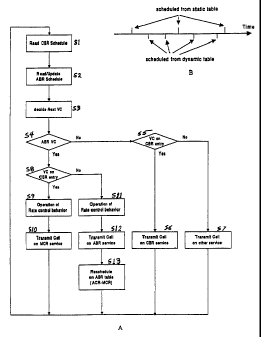
Figure 1A is a simplified flow chart illustration of the schedule processing
of the present
invention, for one cell transmit time. For simplicity of discussion with
respect to the drawing,
r,~
'r~
CA 02305285 2000-03-28
_g_
the static scheduling information is referred to as a CBR schedule. The first
step of the process
is for the scheduler to read its static CBR-type static scheduling information
for the respective cell
transmit time (S 1 ). The scheduler also reads and updates dynamic scheduling
information for
ABR services, during the respective cell transmit time (S2). For example, the
scheduler may
access a link list of ABR virtual circuits and place identifiers for those
circuits, if airy, that have
a cell awaiting transmission on a work list. Based on the scheduling
information (S l and S2), the
scheduler will identify the next virtual circuit, i.e. the circuit that will
carry a cell in the particular
cell transmit time (S3). For example, if the static CBR scheduling information
lists a virhial
circuit connection (VCC) with CBR or MCR service, then the scheduler
identifies that VCC for
1 o use of this cell transmit opportunity. If there is no cell scheduled for a
higher priority service than
ABR, then the scheduler goes to a work list to identify an ABR circuit with a
cell that is ready
and awaiting transmission. The scheduler then identifies that ABR VCC for use
of this cell
transmit opportunity.
The scheduler goes through one or more logic steps for branching of the
process
depending on the type of transmission scheduled. First, processing branches
based on whether
the identified next virtual circuit (VC) is an ABR circuit (S~). If not, then
the process next
branches based on whether the identified virtual circuit (VC) is a CBR circuit
(SS). If the
identified circuit is a CBR type circuit, then the scheduler initiates
transmission of the cell for that
service (S6). If the identified circuit is not a CBR type circuit, then the
circuit relates to some
?o other type of service (such as VBR), and the scheduler initiates
transmission of the cell for that
service (S7).
Returning to step S4, if the scheduler determines that the next VC identified
for use of the
present cell transmit opportunity is an ABR circuit, then the scheduling
process branches to step
S8. In that step, the process flow branches again based on whether or not this
ABR circuit was
identified for the transmit opportunity from the static CBR scheduling in step
S 1. If the scheduler
identified the ABR type VCC from the static CBR schedule information, then the
transmission
is for providing a non-zero MCR for the ABR circuit. The scheduler therefore
executes its flow
control functions relating to the VCC (S9), for example including calculation
of the current ACR
value for the ABR service circuit. The scheduler then initiates the actual
transmission of the cell
(S 10). This transmission step provides a minimum cell rate transmission.
In step S8, if the scheduler identified the VCC from the dynamic ABR
processing
information, then the scheduler executes its flow control functions relating
to the VCC (S11) and
:.~c
,.
w
CA 02305285 2000-03-28
WO 99/Z6446 PCT/US98/24560
-9-
initiates the actual transmission of the cell (S 12). This transmission step
provides a cell
transmission because the transmit opportunity was 'available' for use by the
particular ABR type
VCC. Unlike the other process flow for ABR transmission for MCR service, the
scheduler must
also reschedule the ABR service for the circuit within the dynamic ABR
processing information
(S13). In an ABR service with a minimum cell rate of zero, the rescheduling
would be
proportional to the reciprocal of the allowable cell rate (ACR). However, for
an ABR circuit
having a non-zero minimum cell rate (MCR), the rescheduling is proportional to
the reciprocal
of the difference between the allowable cell rate (ACR) and the minimum cell
rate (MCR). The
rescheduling operation is discussed in more detail below, with regard to the
preferred table
1o embodiments of the dynamic ABR scheduling information.
Figure 1B illustrates opportunities for cell transmission over one virtual
circuit
connection, where the circuit has ABR service with a minimum cell rate. In the
illustrated
example, the static table scheduling provides three transmit opportunities
(above the time line)
within some defined time period. Those opportunities are guaranteed and always
used by the
particular virtual circuit. The dynamic scheduling operations also provide
transmit opportunities
for the circuit {below the time line). The opportunities provided by the
dynamic scheduling are
only presented when transmit times are available for this circuit, and the
circuit carries a transmit
cell only if there is a cell ready for that circuit when each opportunity
becomes available. In the
simple example illustrated, the dynamic scheduling provides three transmit
opportunities for the
2o virtual circuit within the defined time period, and the dynamic scheduling
provides four more
transmit opportunities for the circuit within that same period. The total
opportunities within the
time period correspond to the actual bandwidth used by the circuit.
The preferred embodiments of the present invention schedule ATM cell
transmissions for
CBR service, VBR service, ABR service with zero minimum cell rate and ABR
service with non
zero minimum cell rate. The preferred embodiments support all of these
services on a link
carrying traffic through multiple virtual path connections (VPCs).
The preferred embodiments of the scheduler utilize static scheduling
information and
dynamic scheduling information. The static information identifies one VPC
assigned or allocated
each cell transmit time. The static information includes at least one field
for identifiers of VCCs
3o having high priority services, such as CBR or MCR service. The scheduler
uses the dynamic
scheduling information for ABR service. The scheduler indexes appropriate
dynamic scheduling
information for each cell transmit time in which the scheduler identifies the
associated VPC in
CA 02305285 2000-03-28
- .,~ .. : . - , ,. ." ., ,
> ; ,
~ , . , . , v .,
. . . ~ a n ~ s a
- -
the static table. Using this information, the scheduler accesses a link list
of VCCs, associated
with the same VPC. In this case, the VCCs are circuits having ABR service. The
scheduler adds
the VCC identifiers from the link list to a work list associated with the
currently indexed VPC.
If there is no cell to transmit for a lugher priority service, the scheduler
goes through the work list
for the indexed VPC, to identify a VCC having a cell to transmit and initiates
transmission of that
cell for the identified VCC.
The ATM tragic scheduling of the present invention may apply in a variety of
ATM
processing devices, such as ATM edge devices and other ATM routers and/or
switches. The
preferred implementation of the present invention applies the scheduling
principles in a
1o segmentation and reassembly circuit, typically used in an ATM user network
interface (UNI).
A high level functional description of a network and a UNI containing the
scheduler is presented
followed by a discussion of the preferred embodiments of the scheduling tables
and processes
implemented in the segmentation and reassembly circuit.
Figure 2 illustrates a user network interface (UNI) 10 providing a two-way
data
communication connection between a local area network (LAN) 1 l and a high
speed ATM link
17. The ATM link 17 typically connects to a switch or router of an ATM network
(not shown).
The LAN 11 provides packet data communications between various data devices
connected
thereto. In the simple example illustrated, the LAN 1 lconnects to a plurality
of PCs 13 and to
one or more servers 15. The UNI 10 and the connection thereof through the LAN
11 enables the
2o PCs 13 andlor the server 15 to send and receive data communications over
assigned virtual
circuits on the ATM link 17. As discussed in more detail later, the
segmentation and reassembly
circuit 23 assigns virtual channel connections (VCCs) to data communication
services from the
PCs 13 and the server 15 and schedules transmissions depending on the types of
service and
bandwidths allocated to each of those data devices.
The ATM segmentation and reassembly circuit 23 controls the data flow between
the cell
based virtual circuits assigned on the ATM link and the packet based virtual
circuits through the
LAN 11 to the data devices 13, 15. The circuit 23 segments and adapts outgoing
data for ATM
transport and schedules transmission in assigned virtual paths and circuits.
As part of this
operation, the circuit 23 inserts VPIs and VCIs in the cell headers to
logically place cells in the
3o virtual paths and circuits. The circuit 23 also reassembles payload data
from ATM cells into
packets for transport to the data devices. The circuit 23 performs all
necessary address
administration in both directions.
,~40
:~ '~
.,N,..
P
CA 02305285 2000-03-28
., ,..,.. ..
., .; ~ ~ ~ .
. ;- , ,. a
, . .. ", " , ,.
-11-
Operations of the ATM segmentation and reassembly circuit 23 are controlled by
a
microprocessor 27. The microprocessor 27 serves as the node control processor
for the UNI 10,
for example to administer service negotiation between the UNI and the devices
on the LAN 11
and between the UNI and the ATM node at the opposite end of the link 17. The
ATM
segmentation and reassembly circuit 23 also connects to a memory 29, such as a
static random
access memory (SRAM). The circuit 23 stores scheduling tables, Iink lists and
work lists in the
memory 29. Assembled outgoing cells containing segmented data and VPI/VCI
values are
buffered and queued in the memory. Also, payload data from incoming cells is
accumulated in
the memory 29 to form packets for transmission over the LAN 11 to the data
devices.
The LAN 11 carnes data communications in some standard type of packet data
protocol,
such as Ethernet. The packets include media access control layer addressing
information, to
facilitate two-way communication over the LAN. The UNI 10 includes a LAN
interface 21 for
physical connection to the LAN 1 l and for conforming information going to and
from the UNI
10 to the particular LAN protocol. The LAN interface 21 provides a two-way MAC
level
connection or interface to the ATM segmentation and reassembly circuit 23.
The link 17 carries ATM cells in some high speed transport format. For
example. the link
may be a DS3 commlmication channel on electrical cable or an OC-1 or OC-3 on
optical fibers.
The ATM segmentation and reassembly circuit 23 connects through lts physical
interface port to
a link interface 2~. The link interface 25 conforms the ATNI cell information
going to and from
the UNI 10 to the signal type (electrical or optical) and the protocol (DS or
SONET) of the link
17. The DS and OC protocols cited are examples onl~~, and if other high speed
protocol links are
used, an appropriate interface 25 would couple the UNI to the particular link
and perform the
necessary interface of the UNI to the link.
One example of a chip capable of serving as the circuit 23 is the AToM4
manufactured
by Digital Equipment Corporation and Toshiba. In the outgoing direction, the
ATM
segmentation and reassembly circuit 23 adapts information from LAN packets for
ATM cell
transport. The circuit 23 also maps packet address information into virtual
path and circuit
identifiers, in order to transmit cells for particular devices or services in
assigned virtual circuits
over the ATM link 17.
3o Figure 3 is a high level functional block diagram of the ATM segmentation
and
reassembly circuit 23. The circuit 23 provides the functions required to
implement a variety of
high-performance ATM User Network Interfaces. This includes packet stream to
circuit
_;
,,,,,.,
C''VY
~~h
CA 02305285 2000-03-28
WO 99/26446 PCT/US98/24560
-12-
selection, ATM Adaptation Layer (AAL), segmentation and reassembly (SAR), and
cyclic
redundancy (CRC) generation and checking. The circuit 23 contains mechanisms
to support
traffic shaping, varieties of ATM flow control protocols, and Operations
Administration and
Maintenance (OAM) flows. The ATM segmentation and reassembly circuit 23
interfaces with
a variety of physical layer chips by Utopia or specific interfaces 25, to
facilitate media interface
connection to DS3, E3, and HSSI links, etc.
The circuit 23 receives packets from the LAN interface 21 or the like for
transmission on
the ATM link 17 via a byte-wide data interface with one parity bit (TxInData)
that runs at 12.5
MHz or 25 MHz. The control interface (TxIn Control) includes packet
delineation and byte flow
to control. The flow control signal is used to hold off transmission of data
during periods where no
buffers are available for the data to be transmitted. The receive portion of
the packet interface
is also byte wide for data with one parity bit (TxOut Data), and runs at the
same speed as the
transmit interface. There is a separate control channel (RxOut Control), which
indicates receive
packet delineation and error status.
The segmentation and reassembly circuit 23 connects to the actual link
interface 25
through a physical link interface or port. The physical link interface
consists of a byte-wide data
path for both transmit (TxOut Data) and receive {RxIn Data). In all modes, the
link interface is
slaved from the link clock inputs. Speed matching FIFOs are used between clock
boundaries.
Byte transmission/reception to/from the link is controlled by either a gapped
link clock or an
overhead/valid indication signal on the control lines.
The cell memory interface consists of a 64-bit data bus (Cell Memory Data),
with two
additional parity bits and a 20-bit address bus (Cell Memory Address). Write
enable and output
enable signals are provided separately. An ATM segmentation and reassembly
circuit memory
word is 65 bits wide. The preferred embodiment of the ATM segmentation and
reassembly
circuit 23 is capable of addressing up to 1 Meg word (BMbytes) of memory. The
external
memory is used for storing ATM cells that are awaiting transmission or are
being reassembled,
records, traffic schedules and free buffer pools. The amount of memory
required depends on the
number of circuits being used in a particular application. Currently, 1 MB of
memory is used to
support 4096 circuits.
The segmentation and reassembly circuit 23 connects to the microprocessor 27
through
a node processor interface or port. The node processor interface uses a 16-bit
data and 7-bit
address configuration. This port uses a synchronous Motorola 68K style
interface, running at
CA 02305285 2000-03-28
WO 99126446 PCT/US98124560
-13-
12.5 or 25 MHz. All of the chip control and status registers (CSRs) can be
accessed directly
through this interface. The external memory 29 also is accessed indirectly
through this interface.
As shown in high level form in Figure 3, the segmentation and reassembly
circuit
essentially comprises four processing engines, a segmentation engine 31, a
cell transmit engine
33, a reassembly engine 35 and a packet relay engine 37. Figure 4 shows the
elements of the
segmentation and reassembly circuit 23 in somewhat more detail.
As shown in Figure 4, the segmentation engine 31 receives packets from a
transmit MAC
interface 41. The segmentation engine 31 segments packets into either AAL3/4
cells or AALS
cells, according to the virtual circuit state that is set up for each packet.
At the start of a packet,
t o the segmentation engine 31 uses a region of the packet header to identify
the particular ATM
circuit that the cells should be queued on. Each ATM virtual circuit is
identified with one of
several virtual path connections (VPCs) and with a specific virtual circuit
connection (VCC)
within the particular VPC. Up to 4095 separate circuit queues are supported.
The region of the
header used is programmable and depends on the packet format, e.g., the format
used on the LAN
11 in the example in Figure 2.
The segmentation engine 31 supplies the cells to a memory controller and
scheduler 43.
The controller and scheduler 43 stores the cells resulting from the
segmentation in external
SRAM (memory 29) for transmission by the cell transmit engine 33. In the
simplified
embodiment illustrated (Figure 4), the transmit engine 33 includes a cell
transmitter and scheduler
2o 45 and transmit FIFO buffers 47 which connect to the transmit link portion
49 of the physical link
interface port. Transmission of a cell segmented from a packet can occur while
the rest of the
packet is still being segmented and hence transmit "cut through" is supported.
The cell transmit engine 33 services up to 4095 transmit queues for CBR, VBR,
ABR and
UBR traffic. CBR and VBR traffic is served according to a precomputed traffic
schedule that is
stored in external SRAM, using one or more schedule tables in accord with the
invention. This
schedule tables) can be used for peak-rate traffic shaping on a per circuit
basis. The manner in
which this table is filled out can also allow prioritization of traffic and
overbooking of bandwidth.
The granularity of bandwidth assigned to circuits is programmable by
appropriate programming
of the table(s).
3o A speed-matching FIFO 47 is associated with the cell transmit engine 33 to
account for
the different clock speeds used for the core process (25 MHz) and the link
process (0-25 MHz).
CA 02305285 2000-03-28
WO 99126446 PCT/US98I24560
- 14-
The cells are simply output as a stream, e.g., for an STS-3c link. The byte
stream output can be
held off by either gapping the link clock or asserting the overhead indication
signals.
The reassembly engine 35 receives cells through a receive portion 51 of the
physical link
interface. This engine 35 includes a FIFO 53 and a reassembly section 55. The
reassembly
engine 35 receives cells in byte-wide format from the link. The_FIFO 53
provides speed matching
between the link clock domain (0-19.44 MHz) and the core process clock domain
(25 MHz).
Packet reassembly in section 55 begins by taking a cell from the FIFO 53 and
looking up
the receive circuit identification and state, which are stored in external
SRAM (memory 29). The
index to the receive circuit state table is based on individual lookups of the
VPI field, the VCI
field, and possibly the MID field if AAL4 is being used. If the circuit lookup
indicates that the
cell should be accepted, the cell is written to a free cell buffer in external
memory 29. If a packet
reassembly is completed by the addition of this cell data, the list of cells
comprising the packet
is moved to one of two packet lists, depending on priority bit setting for
this circuit, and the
circuit state is cleared. Otherwise, the circuit state is updated and written
back to memory. FuII
AALS or AAL3/4 checking is done, including CRC checking, length field
checking, segment type
checking, and sequence number checking.
The packet relay engine 37 comprises a packet dequeuer 57. The packet relay
engine 37
services two prioritized queues each of which contains a list of cell buffers
that represents
reassembled packets. The reassembly engine 35 places reassembled packets into
this queue and
2o indicates to the packet relay engine 37 when a packet is ready for
servicing. Each packet contains
a pointer to the circuit that it was received on. The packet relay engine 37
provides the MAC
destination address in the header of the reassembled packet. The packet header
and the complete
packet are passed to the MAC interface 37. The RxOut MAC interface 59 uses the
MAC protocol
to deliver packets. This protocol delineates the packets with start and end
markers and it indicates
the status of the packet, e.g., good or bad CRC. In the illustrated example,
the receive MAC
interface 59 {Figure 4) supplies the reassembled packet to the LAN interface
21 for transmission
over the LAN 11 to the destination device 13 or 15 (Figure 2).
The above description of general transmit and receive operations of the ATM
segmentation and reassembiy circuit 23 is provided for understanding the
context of the preferred
3o implementation of the present invention. In accord with the invention, the
scheduler associated
with the cell transmitter 45 schedules a variety of different types of traffic
on a hierarchical basis
for a plurality of virtual paths within the ATM link. That scheduler
implements a process similar
CA 02305285 2000-03-28
, . . .. ' .. ~ a
.~ o .- . ; ~ v n
.~ ~ ., , s, ,
., n .._ nay ,r, nn~ c,
-15-
to that of Figure 1 using one or more scheduling tables. Further discussions
will concentrate on
hierarchical scheduling using two implementations of the scheduling table(s).
Figure 5 depicts a simplified example of a first table embodiment, i.e. a
single scheduling
table, used in the scheduler. The scheduling table includes multiple lines
indexed by cell transmit
time. The first field in each line contains an identifier or index for one of
the VPCs. This VP
index corresponds to and may be the same as the virtual path identifier (VPI)
inserted in the cell.
The VP index in a line effectively assigns the cell transmit time of that line
to the indexed virtual
path connection (VPC).
The next two fields in each line identify VCCs for different levels of service
priority, and
1o the succeeding two fields point to lists of additional VCCs having a
different type or level of
service. The VC or VCC identifiers used in this table (and other tables
discussed later) may take
the form of internal numbers or names arbitrarily assigned as the identifiers.
In such a case, the
segmentation and reassembly circuit 23 will translate those identifiers into
actual ATM standard
virtual circuit identifiers (VCIs) for insertion into the cells transmitted
over the ATM link by the
interface chip. Alternatively, the segmentation and reassembly chip 23 may
utilize ATM VCIs
as the internal virtual circuit identifiers.
Returning to Figl~re 5, after the VP index, the next field in each line
contains an identifier
for a VCC having a high priority service. The high priority service may be a
VBR service, but
typically the high priority service is a CBR service. In accord with the
invention, at least some
of the VCCs identified in the high priority field are VCCs having ABR service.
The
identification of such an ABR circuit in the high priority field supports the
MCR for those VCCs.
As discussed more later, certain processing varies depending on whether or not
a VCC identified
in a high priority field receives an MCR transmission for an ABR service. To
distinguish VCCs
on this point, the high priority field has an associated MCR flag. If the flag
is set, the VCC
identified in the field is receiving an MCR transmit opportunity.
The next field in the table contains an identifier for a VCC having a low
priority service.
Here, low priority means that the service is lower in priority than the
service (if any) identified
in the high priority field. In preferred implementations, the high priority
service is a CBR service
or an MCR service, and the low priority service is VBR service. As discussed
more below, other
services, such as ABR traffic, actually have still lower priority than those
identified in the 'low
priority' field.
~~~~5
P
CA 02305285 2000-03-28
WO 99126446 PCTIUS98124560
-16-
In operation, the scheduler moves a pointer to traverse the table as it
increments the cell
transmit time. The order of accessing the lines of the schedule table is a-b-c-
d-e-f g-h-a....
Different VPCs may use the same VCC identifiers, but each combination of a VPC
identifier and
a VCC identifier uniquely identifies one circuit. For each cell transmit time,
the scheduler
accesses one line in the table to perform a variety of scheduling functions,
to identify a circuit for
transmission in the cell transmit time. The scheduler first identifies a VPC
from the currently
indexed line. If the scheduler fords a VCC identifier in the high priority
column, the scheduler
initiates transmission of a cell over that VCC. For example, during cell
transmit time a, the table
identifies VP1 and VC1, therefore the scheduler initiates transmission of a
cell for that circuit
to connection. The MCR flag is not set, indicating that the service is a CBR
service instead of MCR
service for an ABR type circuit. During cell transmit time e, the table
identifies VP1 and VCS,
therefore the scheduler initiates transmission of a cell for that circuit
connection. The MCR flag
is set, indicating that the service is an MCR service for the ABR type circuit
VCS, therefore the
scheduler performs the requisite flow control processing for that circuit.
The number of entries of the ABR type VCC in the high priority field defines
the
guaranteed bandwidth, that is the MCR, attributed to the particular ABR type
circuit. This rate
is static. The level of MCR for an ABR service is negotiated at call set up.
In the example of
Figure 2, the data device 13 or 15 negotiates with the UNI 10 for a particular
type of service, in
this case ABR service and for a minimum cell rate. In accord with the
invention, the negotiated
2o MCR may be greater than zero. Once negotiated, the MCR value does not
change during
communication, the MCR value remains constant in a manner analogous to that of
a negotiated
CBR rate. However, during communications the allowable cell rate ACR varies
with the dynanuc
scheduling of ABR transmissions over the virtual circuit.
Returning to operations using the table of Figure 5, if the scheduler finds no
listing in the
high priority column in a respective cell transmit time, the scheduler looks
to the low-priority
column. If the line identifies a VCC for low priority service, the scheduler
checks the cell queue
in memory 29 to determine if the queue holds a cell that is ready for
transmission over that VCC.
If so; then the scheduler initiates transmission of a cell for that VCC. If
not, the scheduler offers
the cell transmit opportunity to VCCs having lower priority services. In the
examples discussed
3o above, the scheduler initiated transmission for VC1 and VCS, for VP1, in
time slots a and e,
because those VCCs were listed in the high priority field. However, in cell
transmit time b, the
table identifies VP2, but there is no VCC listed in the high priority service
column. The
CA 02305285 2000-03-28
WO 99/26446 PCTIUS98/24560
-17-
scheduler therefore looks to the low priority field in that line of the table.
In this example, the
low priority field for the transmit time b identifies VC3, therefore the
scheduler checks the cell
queue in memory 29. If the queue holds a cell for the VC3 circuit associated
with VP2 that is
ready for transmission, then the scheduler initiates transmission of that cell
for that VCC. If not,
the scheduler offers the cell transmit opportunity to VCCs having lower
priority services
associated with VP2.
For each cell transmit time, the scheduler also uses information from each
line to schedule
ABR services. In the single table implementation, each line specifies a pair
of pointers for ABR
service. The head and tail pointers (H, T) enable the scheduler to select a
link list of VCCs
to associated with the VPC indexed in the particular line of the table. The
link list includes VCC
identifiers for associated circuits carrying available bit rate service type
traffic. The scheduler
accesses the identified Link list stored in memory 29 and may append one or
more of the VCCs
from the link list to a work list. The scheduler may append all of the VCCs
from the accessed
link list to the work list. Alternatively, the scheduler may append VCC
identifiers from the link
list to the work list only for those circuits having a cell ready for
transmission.
In the single table implementation, there could be one work list for all VFCs,
but
preferably the scheduler uses a separate work list for the ABR traffic for
each VPC. Thus, the
scheduler will append one or more VCCs from a particular link list to the work
list associated
with the indexed VPC. When the scheduler detects a cell transmit time for
which there is no high
2o priority service listed and there is no low priority circuit with a cell
ready to transmit, the
scheduler goes to the appropriate ABR work list. The scheduler goes through
the list to select
a source for a VCC for which there is a cell queued and ready to transmit.
Consider scheduling for several VCCs as simplified examples using the
illustrated table.
In the illustrated example, there are four VPCs (VPI to VPO) each having one
fourth of the link
rate assigned as their respective bandwidth. To implement this allocation,
each VPC has its
identifier listed in one-fourth of the lines of the table. In the present
example, the scheduler will
run through similar processes for VP2, VP3 and VPO for time slots b, c and d
respectively. In the
illustrated example, each VPC identifier appears in the line corresponding to
every fourth cell
transmit time. In cell time a, for example, the scheduler accesses the first
line in the table.
3o Based on that line, the scheduler identifies VPI as the VPC assigned this
time slot. The scheduler
checks the high priority field of the first line, identifies VC 1 for high
priority service. There is
no MCR flag set for this transmit time, thus the scheduler treats the VCC as
one having a CBR
CA 02305285 2000-03-28
WO 99/26446 PCT/US98/24560
-18-
service. The scheduler causes transmission of a cell for the VPl circuit VCl
in the present time
slot. The cell transmitted includes VPI and VCI values corresponding to VPl
and VC1. During
the processing for transmit time a, the scheduler also will use head and tail
pointers H1, T1 from
line a to access a link List and may move one or more VCCs from that list to
an ABR work list
associated with VP 1, as discussed above. The scheduler goes through a similar
process to initiate
transmission of a cell for VP1-VCS in time slot e, but the scheduler notes the
MCR flag is set for
that circuit connection. The scheduler initiates certain processing related to
ABR service, in
response to the MCR flag, as discussed in more detail later.
Although not shown, the scheduling table will include additional Lines, and
typically some
of those lines will represent time slots for which there are no high priority
circuits identified. For
example, assume that for transmit time i, the table identified VPI, the high
priority field is empty
and the low priority filed identified VC2. After cell time h, the scheduler
increments cell transmit
time to time i and moves the pointer to that line of the table. Based on that
line, the scheduler
identifies VP1 as the VPC assigned this time slot. The scheduler checks the
high priority field
of the first line and finds no VCC identification. The scheduler next checks
the low priority field.
In this example, that field identifies VC2. Here, VC2 is a different VCC
associated with VP1.
The low priority service preferably is a variable bit rate service. The
scheduler checks to
determine if this VC2 has a cell ready for transmission. If VC2 has a cell
ready to transmit, the
scheduler causes transmission of that cell in the time slot i. The header of
the transmitted cell
2o contains a VPI corresponding to VP1 and a VCI corresponding to VC2. During
the processing
for transmit time i, the scheduler will also use head and tail pointers to
access a link list and may
move one or more VCCs from that list to an ABR work list associated with VPI,
as in the earlier
examples.
If the circuit VC2 for VP1 did not have a cell ready to transmit at time i,
the scheduler
goes to the work list for VP1 to find an ABR circuit with a cell to transmit.
If there are circuits
in the work List, the scheduler uses that list to select an ABR circuit with a
cell ready. If the work
list was empty before time i, the scheduler may look to the circuits on the
link list accessed at that
time to find a circuit with a cell to send. Assuming that the scheduler finds
an ABR VCC with
a cell that is ready to transmit, the scheduler causes transmission of a cell
over that VCC in the
3o time slot. For example, the scheduler may go down through the VP 1 work
list and identify VCS
for VC 1 as the first circuit on the list with a cell ready for transmission.
The scheduler controls
the ATM transmitter to send the cell for that circuit over the link in the
transmit time i. In this
CA 02305285 2000-03-28
WO 99/Z6446 PCTNS98124560
-19-
manner, VCS for VPI uses an ABR transmit opportunity. This opportunity is in
addition to the
MCR opportunity provided in the earlier example of transmission in time slot a
based on
identification of that same circuit in the high priority field of the table.
The scheduler indexes through the table as it repeatedly increments the cell
time and
moves the pointer. As it does so, the scheduler performs similar functions to
identify virtual
circuits within the other VPCs for transmission scheduling. As another
example, when cell
transmit time c occurs, the scheduler accesses the corresponding line in the
table: Based on that
line, the scheduler identifies VP3 as the VPC assigned this time slot. The
scheduler checks the
high priority field of the first Line. In this example, there is no CBR or MCR
service VCC listed.
The scheduler next checks the low priority field. In this example, that field
identifies VC2
associated with VP3. The low priority service preferably is a variable bit
rate service. The
scheduler checks to determine if this VC2 has a cell ready for transmission.
If VC2 has a cell
ready to transmit, the scheduler causes transmission of that cell in the time
slot c. The header of
the transmitted cell contains a VPI corresponding to VP3 and a VCI
corresponding to VC2.
During the processing for transmit time c, the scheduler will also use head
and tail pointers H3,
T3 to access a Link list and move VCCs from that list to an ABR work list
associated with VP3.
Assume now that in time c circuit VC2 for VP3 did not have a cell to transmit.
In such
a case, the scheduler goes to the work list for VP3 andlor to the link list
accessed in that time slot,
to find an ABR circuit with a cell to transmit. Assuming that the scheduler
finds a VCC with a
2o cell that is ready to transmit, typically from that work list, the
scheduler causes transmission of
a cell over that VCC in the time slot c. If the VCC with ABR service has an
MCR greater than
zero, it will have its identifier listed in the high priority field of another
line (not shown) identified
with VP3, in a manner similar to that for VCS associated with VP 1.
The scheduler indexes the table at the cell rate of the link. The scheduler
executes the
hierarchical scheduling process for each line of the table. When the scheduler
completes
processing for the last line, it increments the cell transmit time in such a
manner as to cycle back
to time a and index the first line of the table. In this fashion, the
scheduler repeatedly cycles
through the table to present transmit opportunities for specific circuits
identified in the table and
in the ABR work lists.
3o The listing of the VCCs in the high and low priority columns of the tables
allocate
transmit opportunities and bandwidth to those services. Constant bit rate
service is provided by
entries in the high priority fields of the table, and the number of entries in
those fields determines
CA 02305285 2000-03-28
WO 99/26446 PCTIUS98/24560
-20-
the bandwidth within the VPC allocated to the particular VCC for its CBR
service. In the above
example, VC1 for VP1 appeared only in the high priority column. The circuit
VP1-VC1 receives
CBR service because the table guarantees that circuit an opportunity to
transmit each time that
cell transmit time a occurs. The circuit VP 1-VC 1 will always transmit a cell
in that time slot,
even if the cell contains no data, to maintain a constant bit rate flow.
Similarly, MCR service for
ABR circuits is provided by entries in the high priority fields of the table,
and the number of
entries in those fields determines the bandwidth within the VPC allocated to
the particular VCC
for its MCR service. The circuit VPl-VCS receives MCR service because the
table guarantees
that circuit an opportunity to transmit each time that cell transmit time a
occurs. The circuit VP 1-
1o VCS will always transmit a cell in that time slot, even if the cell
contains no data, to maintain a
constant bit rate flow.
Similarly VC2 for VP3 appeared in the low priority column in a Line which
included no
higher priority entry. That entry guarantees VC2 an opportunity to transmit
each time that cell
transmit time c occurs. If the VCC circuit uses the opportunity every time, it
receives its
maximum allowable cell transmission rate. However, at times this VCC may not
have a cell that
is ready to transmit. If the VCC does not transmit in that slot, its
transmission rate decreases, and
the transmit opportunity passes to the still lower priority ABR service VCCs
associated with VP3.
The table structure also supports a combination of CBR and VBR services for a
given
circuit, effectively to provide such a circuit with a variable rate service
having a guaranteed
2o minimum transmission rate. If a circuit, such as VC2 for VP3, has one or
more entries in the high
priority column, those entries guarantee a minimum cell rate, essentially as a
CBR service (see
the Line for time slot g). The appearance of the same VCC in the low priority
field (e.g. in the line
for cell time c) provides an added variable rate opportunity that the circuit
need not always use.
As shown in Figure S, the first embodiment of the schedule table also includes
a column
specifying next serve time, for ABR services. The 'next serve time' AD is used
to reschedule
ABR service for a link list. For this purpose, the scheduler takes the link
list pointers from the
previous point in the table and moves them down the table by the amount
identified in the 'next
service time' field, and inserts the head and tail pointers into a table line
associated with the same
VPC. The scheduler dynamically calculates these next service times, for
example, based on
3o transmissions during the MCR processing of the static information and ABR
transmissions during
processing of the dynamic scheduling information.
CA 02305285 2000-03-28
WO 99126446 PCTNS98/Z4560
-21 -
This form of rescheduling for ABR service is complex. The table must specify
next serve
time. Each ABR link list may have a different rescheduling interval 0D, and in
fact, the interval
may change over time depending on traffic. The calculation for an ABR service
with a non-zero
MCR is different from that for an ABR service with an MCR of zero. Also, any
change in
bandwidth allocations requires redoing all of the table entries, for CBR, VBR
and ABR services.
To provide a more flexible scheduling for ABR service and easier rescheduling,
the
second embodiment of the scheduling process uses separate tables for ABR
traffic. Specifically,
one static table indexes VPCs and identifies high and low priority VCCs for
CBR, MCR and
VBR traffic. There is a separate, dynamic ABR table associated with each
respective VPC.
l0 When the scheduler accesses a line of the static table for a given cell
transmit time, it first
identifies a VPC assigned that slot for its use. The scheduler processes CBR,
MCR and VBR
tragic using VCC identifiers from the indexed line of the static table, in
essentially the same
manner as for the single table of Figure 5. The scheduler accesses a dynamic
ABR table for the
indexed VPC to retrieve a link list and append that list to a work list
associated with the VPC.
Moving the pointers for that list down the respective ABR table reschedules
service for a specific
link list of VCCs by an appropriate number of lines. It should be noted, that
with the second
implementation, a reallocation of bandwidth between VPCs requires modification
of the number
of lines each VPC has in the static table. However, the ABR tables require no
modification.
Figure 6 illustrates one example of a static scheduling table; and Figures 7A
to 7D
2o illustrate simplified portions of the dynamic scheduling tables, in accord
with this second
embodiment. Figure 8 illustrates process flow for an ABR work list, in the
second embodiment.
As shown in Figure 6, the static scheduling table includes multiple lines
indexed by cell
transmit time. The scheduler moves a pointer to traverse the static table at
the cell slot time rate
of the ATM link, i.e. the pointer for this table moves to the next line each
time that the scheduler
increments the cell transmit time. Each line of the table corresponds to one
cell transmit time
slot. When the scheduler increments the cell transmit time after the
processing of the last line of
the table, the scheduler moves the pointer to the first line of the static
table.
The first field in each line contains an identifier or index for one of the
VPCs. The VPC
index in a line effectively assigns the cell transmit time of that line to the
indexed VPC. In the
3o illustrated example, again there are four virtual path connections (VPCs),
and the static table
includes virtual paths indexes VP1, VP2, VP3 and VPO for those virtual paths.
Each row in the
table represents an opportunity for transmission of a cell for the indexed
VPC. In the example,
CA 02305285 2000-03-28
WO 99126446 PCTNS98I24560
-22-
each VPC receives a transmit opportunity every fourth time slot. Thus each VPC
may use up to
25% of the link bandwidth.
The next field in each line of the static table is provided for an identifier
for a VCC having
a high priority service. Some lines include identifiers in this field, some do
not. The high priority
service rnay be a VBR service, but again preferably relates to either a CBR
service or the MCR
portion of service for an ABR circuit. The status of an MCR flag (0 or 1 )
indicates whether or
not the VCC in the high priority field is transmitting for the MCR of an ABR
service. The next
field in the table is provided for an identifier for a VCC having a low
priority service. Some lines
include an entry in the low priority field, some do not. The term 'low
priority' only means that
1 o the service is lower in priority than the service (if any) identified in
the high priority field. Again,
other services, such as ABR traffic, actually have lower priority than those
identified in the 'low
priority' field. The scheduler processes the high and low priority entries in
essentially the same
manner as in the earlier embodiment.
The scheduler first presents the send opportunity to the VCC (if any)
identified in the high
priority field. High priority entries in the static table typically are used
for CBR services and for
a constant bit rate type service to provide a non-zero MCR for an ABR circuit.
Each cell time
that the scheduler hits a VCC for a CBR service in the high priority field of
a line, the scheduler
schedules cell transmission for that VCC. Each cell time that the scheduler
hits a VCC for an
MCR service in the high priority field of a line, the scheduler schedules cell
transmission for that
2o VCC, notes the MCR flag and executes the appropriate flow control algorithm
for the particular
ABR circuit. If there is no data to send, the VCC having the CBR service or
the MCR service
still transmits a cell, albeit a cell having the VPI and VCI values assigned
to the circuit in the
header but having no data in the payload. If the high priority field were used
for some service
other than CBR or MCR, e.g. VBR, then the scheduler would determine if there
is a cell buffered
in the memory awaiting transmission over the high priority VCC.
The high priority processing often does not cause scheduling of transmission
in the
respective cell time slot. Typically, this occurs because there is no VCC
listed in the high priority
field (for CBR or MCR), or possibly because a VCC in that field has VBR
service but no cell is
ready for transmission on that circuit. In any such case, the scheduler passes
the cell transmit
opportunity to the VCC (if any) identified in the low priority field. The low
priority entries
typically are used for variable bit rate services. This service provides
transmit opportunities that
the circuit may not always use, typically to support bursty data traffic. Each
cell time that the
CA 02305285 2000-03-28
WO 99/26446 PCT/US98/24560
-23-
scheduler hits a VCC for a VBR service in the low priority field of a line,
the scheduler offers the
cell transmit opportunity to that specific VCC. If the scheduler determines
that the identified
VCC has a cell buffered in memory and ready to send at the present cell
transmit time, then the
scheduler will initiate transmission of the cell for that VCC. If not, then
the scheduler looks to
circuits having still lower priority service, such as available bit rate
service, to identify a circuit
and a cell to transmit.
As in the earlier embodiment, by placing identifiers for the same VCC in the
high priority
field and the low priority field, in different lines of the table, the
scheduler actually provides a
variable bit rate service with a guaranteed minimum bandwidth. If the
scheduler finds the VCC
in the high-priority field in one line of the table, the scheduler schedules
the cell transmission for
that VCC during each cell transmit time that indexes that line of the static
table, just as if this
were a CBR service. The number of lines in the table, which include the VCC
identifier in the
high priority field, establishes the CBR-like minimum bandwidth. Appearances
of the VCC
identifier in the low priority field of a number of lines provides additional
bandwidth in the form
of a variable bit rate portion of the service for the particular VCC. The MCR
flag would not be
set, because this combination of CBR and VBR requires no dynamic flow control.
The preferred implementation of the scheduler uses dynamic scheduling tables
for ABR
service. There is a dynamic table for each of the VPCs. The scheduler indexes
a line of the
appropriate dynamic table for each cell transmit time in which the scheduler
identifies the
2o associated VPC in the static table. The scheduler reads one or more
pointers from the line of the
dynamic table and uses the pointers) to access a link list of VCCs, associated
with the same
VPC, having ABR service. The scheduler may add one or more of the VCC
identifiers from the
link list to a work list associated with the currently indexed VPC. In one
implementation, the
scheduler goes through the link list and determines which listed circuits have
cells awaiting
transmissions. The scheduler places the VCC identifiers for such circuits, if
any, on the work list.
If there is no cell to transmit for a higher priority service, the scheduler
initiates transmission for
the first circuit listed on the work list. Alternatively, when the scheduler
accesses the link list,
it may place all of the VCC identifiers on the work list. In this later
implementation, if there is
no cell to transmit for a higher priority service, the scheduler goes through
the work list to
3o identify the first VCC having a cell to transmit and initiates transmission
of that cell for the
identified VCC.
CA 02305285 2000-03-28
WO 99/26446 PCTNS98IZ4560
-24-
The scheduler traverses each dynamic ABR table at the cell rate for the
associated VPC.
That is to say that the scheduler reads the next line of the ABR table, for a
particular VPC, each
time that the scheduler reads the index for that VPC from a line of the static
table. As such, the
speed of the movement of the pointer associated with each ABR is scaled as a
function of the
percentage of bandwidth or cell rate allocated to the respective VPC.
The scheduler maintains a separate dynamic table for ABR services for each VPC
that the
scheduler supports. How often the VCC for an ABR service appears in the ABR
table together
with the number of appearances (if any) of the VCC in the high priority field
of the static table
determines the maximum bandwidth available to the particular VCC circuit. As
noted, a cell is
to transmitted for such a VCC in each cell transmit time corresponding to a
line of the static table
that identifies the VCC in the high priority field. Those transmit
opportunities are guaranteed and
always used. However, during ABR processing, the VCC can only transmit when a
cell time slot
is available for ABR transmission and the particular VCC is the first VCC
identified on the work
list with a cell ready for transmission.
The ABR table is a dynamic table. Each time that a VCC is presented an
opportunity to
transmit, the associated link list is removed from the work list, and the
scheduler moves the head
and tail pointers for that link list down the ABR table to a new location. The
distance down the
table to the new location determines the time delay until the next retrieval
and placement of the
link list on the work list and thus the next opportunity for that ABR VCC to
send a cell. The
2o rescheduling distance is inversely proportional to the difference between
the current ACR for the
circuit and the MCR (if any) for the circuit.
In the example under discussion, there are four VPCs; therefore the scheduler
maintains
four dynamic ABR tables, portions of which appear in Figures 7A to 7D. Each
ABR table
includes a cell time index for each line of the table. However, here the cell
times are only those
assigned to the associated VPC in the static table. Assume for this discussion
that the scheduler
accesses an ABR table for every cell transmit time. For example, in Figure 6,
the static table
shows assignment of times a and a to VP 1. The dynamic ABR table for VP 1
(Figure 7A)
therefore shows lines for times a and e. Similarly, the static table shows
assignment of times b
and f to VP2 and the corresponding ABR table for VP2 (Figure 7B) shows lines
for times b and
3o f. The tables show similar assignments for VP3 and VPO.
Over time, the scheduler indexes down through each dynamic table for each
respective
time slot corresponding to the same VPC as the particular dynamic table. The
scheduler also
CA 02305285 2000-03-28
WO 99126446 PCT/US98/24560
-25-
dynamically updates each of these tables. If the scheduler reaches the current
end of such a table,
it recycles to the current top line of the table and continues on.
Each line of an ABR table includes head and tail pointers H, T. The pointers
identify a
link list of VCCs associated with the particular VPC. Figure 8 shows the flow
of the link list and
s work list processing. In the illustrated example, at time a, the scheduler
reads Hl, Ti from the
ABR table for VPI. The scheduler uses those pointers to retrieve a work list,
in the example
containing identifiers for VC4, VCS and VC7 associated with VP1. The scheduler
could check
the status of the circuits on the link list, and append VCC identifiers to the
work list only for those
circuits having a cell ready to send. In the illustrated example, the
scheduler appends all of the
to VCC identifiers from the link list to the work list. In the example
illustrated, VC6 and VC8 are
presently at the top of the work list for VP 1. The scheduler appends the new
link list to the
bottom of that work list.
When a transmit opportunity fox VPl arises, if there is no higher priority
service ready
to transmit (cell transmit time i in one earlier example), the scheduler goes
to the work list for
15 VPl. In the illustrated example, the scheduler goes down through the work
list to identify the
first VCC on the list that has a cell ready to send. For this purpose, the
scheduler goes down
through the work list, starting with VC6 and checks the cell queue with
respect to each VCC.
Assume for this example that the first VCC with a cell queued and ready to
send is VCS. The
scheduler initiates transmission of the cell for that circuit and reschedules
service for the link list
20 containing VCS. In the example, the scheduler removes the list of VC4, VCS
and VC7 from the
work list and places the pointers Hl, T1 for that list back in the ABR table
for VPI.
The precise placement in the dynamic table depends on the applicable
rescheduling
algorithm. More specifically, in this second embodiment, moving the pointers
for an ABR link
list down the ABR table by some distance DD reschedules service for the VCCs
on that Iink List.
25 As noted earlier, the scheduler traverses the ABR table for a particular
VPC at a fraction of the
cell rate corresponding to the fraction of the link rate allocated to that
VPC. The rescheduling
therefore also must be scaled to the appropriate percentage of bandwidth or
link rate allocated to
the VPC. Also, the distance differs depending on whether or not the ABR
circuit has an MCR
greater than zero. In the preferred process, the distance DD for a circuit
with a zero MCR equals
3o the percentage bandwidth for the associated VPC multiplied by the
reschedule time (OT) for this
ABR VCC. The reschedule time (DT) equals the link rate divided by the allowed
cell rate (ACR)
CA 02305285 2000-03-28
WO 99IZ6446 PCTIUS98/24560
-26-
for the ABR service to the particular VCC. The ACR value varies dynamically
depending on
traffic.
For circuits having a non-zero MCR, the distance far rescheduling for an ABR
VCC in
the dynamic table equals the bandwidth of the VPC multiplied by the total link
rate, and divided
by the difference between the ACR and the MCR for the VCC. Stated another way,
if the
distance is AD, the distance is approximated by the following equation:
(VPCBW)link rate
AD =
ACR - MCR
1o where VPCBW is the bandwidth assigned to the entire VPC, ACR is the
allowable cell rate
currently calculated for the particular VCC, and MCR is the minimum cell rate
for the VCC. The
distance OD is not exact but provides an adequate approximation for
rescheduling if the total
MCR bandwidth is relatively small.
In the above discussed processing, the scheduler accessed the appropriate ABR
table
during the schedule process for each cell transmit time, regardless of the
type of transmission
scheduled in each time slot. In a preferred embodiment, the scheduler skips
access to the ABR
table if the static table identifies an ABR circuit for an MCR transmission.
Returning to the
example illustrated in Figure 6, assume that the circuit VCS associated with
VP1 is an ABR
circuit having a listing in the high priority column of the static table in
the line for time slot e.
2o As discussed above, this listing supports MCR transmissions for that
circuit, in each occurrence
of time slot e. During other time slots associated with VP 1, e.g. time slot a
in the simple example
shown, the scheduler will access the ABR table for VP1. However, the scheduler
will detect the
MCR flag set in the line for time slot e, and the scheduler will not access an
ABR table during
processing for that cell transmit time. As a result, the ABR table for VP1
would have listings
only for those time slots associated with VP 1 in which the scheduler will
access that table, only
for occurrences of time slot a, in the simple example shown in the drawings.
With this preferred processing for ABR circuits with MCR, a more exact
rescheduling
formula should be used. Specifically, for circuits having a non-zero MCR, the
distance for
rescheduling for an ABR VCC in the dynamic table equals the bandwidth of the
VPC minus the
3o total MCR bandwidth for circuits within the VPC multiplied by the total
link rate, and divided
CA 02305285 2000-03-28
WO 99126446 PCT/US98/24560
-27-
by the difference between the ACR and the MCR for the VCC. Stated another way,
if the
distance is ~D, the distance is calculated by the following equation:
(VPCBW - MCRBW)link rate
~D =
ACR - MCR
where VPCBW is the bandwidth assigned to the entire VPC, MCRBW is the total
minimum cell
rate bandwidth for the particular VPC, ACR is the allowable cell rate
currently calculated for the
particular VCC, and MCR is the minimum cell rate for the VCC.
In an actual implementation, the scheduler stores two copies of the scheduling
table
(Figure 5) or two copies of the static table (Figure 6). One copy of the table
is active, and the
other is not. To reprogram the service hierarchy, the microprocessor modifies
the inactive copy
of the table and transfers and changes the active/inactive status of the two
tables. In the second
embodiment, Figures 6 and 7, the dynamic tables need not be changed each time
the
microprocessor modifies the static table. The microprocessor modifies the
dynamic tables on-the-
fly, as part of its rescheduling process, to add and delete ABR circuits. It
may be helpful to
consider some examples.
In the second implementation, tear-down or set-up of a real-time connection
requires
modification of the static schedule table. One control bit in a control and
status register indicates
which of the two static tables currently is in use. The microprocessor
negotiates service with the
2o appropriate data device 13 or 15 to define the circuit to be set up or torn
down, and modifies the
inactive static table to reflect this change. After completion of modification
of this table, the
microprocessor flips the control bit to activate usage of the new static table
and to deactivate the
other table. When the current time pointer reaches the end of the old table
and wraps around to
the cell time for the top of the table, the base of the new static table is
copied to the current time
pointer, and the scheduler begins using the new static table. The
microprocessor uses this
process, for example, for CBR circuits and for the MCR service to ABR
circuits.
To set up or tear down a non-real time connection, the microprocessor
initiates a treatment
of the circuit by modifying the rescheduling process in the appropriate
dynamic, ABR table. For
example, to set up such a connection, the UNI 10 negotiates the level of
service (type and
3o bandwidth) for a new logical connection. The UNI 10 stores data mapping the
address
information for the portion of the circuit on the LAN to the assigned ATM
identifiers. The
CA 02305285 2000-03-28
WO 99/26446 PCTIUS98/24560
-28-
microprocessor modifies a status register associated with the circuit. When
the circuit first has
trai~c to send, the pointers for the link list containing the circuit are
added to the dynamic table
for the appropriate VPC. To tear down a connection, the status register for
the circuit is changed
to inactive. After the next service opportunity is offered to the circuit, the
scheduler will not
reschedule service for that circuit in the ABR table. If the ABR service has
an MCR greater than
zero, the microprocessor also modifies the static table in the manner outlined
above.
As discussed above, the number of appearances of a VPC identifier in the VP
index of the
static table determines the bandwidth allocation to the VPC. To modify the
bandwidth for a VP,
the microprocessor changes the inactive copy of the static table to include
the VPC in the
1 o appropriate number of lines for the new level of bandwidth and then
activates the modified copy
of the table in the manner outlined above.
If the scheduler completes the static table, dynamic table and work list
processing without
finding a circuit with a cell to send, the scheduler could initiate
transmission of a null cell, but
preferably the transmit opportunity passes down to one or more lower level
service circuits. In
the preferred implementation, the segmentation and reassembly circuit supports
a number of other
types of flow control, such as quantum flow control. For simplicity of
discussion, assume that
there is one lower level service, quantum flow control. Quantum flow control
(QFC) processing
maintains a 'credit' for each VCC subscribing to the service. For each VPC,
the scheduler
maintains a separate queue of VCCs for QFC based services. The scheduler
identifies the VPC
2o from the VP index in the static table and performs its processing for CBR,
MCR, VBR and ABR,
as discussed earlier. If the VPC assigned to a particular cell time has no
cell ready to send for any
VCC having those services, the scheduler looks to a queue of VCCs for QFC,
associated with the
currently identified VP, to f nd a QFC VCC that may have a cell to send.
When a QFC opportunity to transmit arises with respect to one VPC, the
scheduler checks
if the next VCC on the queue for that VPC has any transmit credit remaining.
If so, the scheduler
initiates transmission of a cell for that VCC. If the VCC has no credit
remaining, then the
scheduler looks to the next VCC in the QFC queue to see if that VCC has any
transmit credit
available. The scheduler continues down through the QFC queue in this manner
until it finds a
VCC with a cell that is ready to transmit or until in reaches the end of the
QFC queue. If the QFC
3o processing identifies a VCC with a credit and a cell that is ready to send,
the scheduler initiates
transmission of the cell for that VCC.
CA 02305285 2000-03-28
WO 99126446 PGT/US98/24560
-29-
To ensure detailed understanding, it may be helpful to go through a specific
process flow,
with emphasis on the processing of the second embodiment of the scheduling
tables. Figure 9
is a flow chart illustrating this scheduling process.
The scheduler reads the pointer for the current cell transmit time (S 1 I 1 )
and accesses the
line in the static table corresponding to the indexed cell time. From the
first field in the line of
the static table for that time slot, the scheduler identifies the VPC assigned
that time slot. The
scheduler next checks the high priority field of that line (S 112). The
scheduler then determines
if there is a VCC listed, meaning that a cell must be scheduled for
transmission in this slot for the
identified VCC (5113). In the preferred embodiment, if there is a VCC listed
in that field, the
1 o identified VCC has a CBR or MCR service allocated to use of that time
slot. Step S 113 produces
a branch to step S 114.
As discussed above, there is a flag in high priority table if the VCC is for
MCR service
for an ABR type VCC. When the scheduler is examining the high priority field
in the static table
and finds a VCC, the scheduler also checks the MCR flag (S 114). If set, the
scheduler recognizes
this VCC as having MCR service and sets an MCR ready bit, indicating cell
transmission for
MCR service (S 115). The scheduler assigns this cell transmit slot to the
identified ABR VCC
having a non-zero MCR. If the MCR flag is not set when checked in step S 114,
the scheduler
sets a bit indicating CBR ready and assigns this cell transmit slot to the
identified CBR VCC
(S 116).
2o True CBR service does not require an ACR calculation or any flow control
processing.
However, the transmissions for ABR VCCs identified in the static table require
calculation of the
ACR for the circuit and flow control processing. Thus, when the scheduler
initiates transmission
for the VCC in response to an ABR listing in the high priority filed of the
static table, the
scheduler notes the MCR ready flag and calculates the ACR for the identified
VCC circuit. The
MCR ready flag also triggers flow control and reschedule processing, based in
part on the ACR,
as discussed above.
If the analysis in steps S 112, S 113 identified a high priority VCC,
processing flows to
either step S 115 or step S 116 and from there to step S 120. However, in step
S 113, if the high
priority field in the indexed line does not include a VCC for a CBR or MCR
service, the
3o scheduler next accesses the low priority field in the table (S 117). In the
preferred embodiment,
the low priority fields are used to identify VCCs for variable bit rate
services. In any given line
of the table, there may or may not be a low priority entry. If there is an
entry in this field, the
CA 02305285 2000-03-28
WO 99126446 PCTIUS98/24560
-30-
scheduler checks the cell queue for the circuit identified, to determine if
that circuit has a cell to
send (S 118). If so, the scheduler sets a bit indicating VBR ready and assigns
this cell transmit
slot to the identified VBR VCC (S 119), and processing flows to step S 120. If
there is no VCC
listed in the low priority field or if a VCC is listed but has no cell ready
to send, then the
scheduler will not set the ready bit for ABR transmission, meaning processing
flows directly from
step S 1 I 8 to step S 120.
In the illustrated embodiment, the scheduler reads the head and tail pointers
from the
indexed line of the static table in step S 120. The head and tail pointers
point to a link list of
VCCs having ABR service. Using the link list, the scheduler retrieves the link
list from the
to memory 29 and may move one or more of the VCCs contained in the particular
link list to the
work list for the currently identified VPC (5121). There are a number of
possible algorithms that
the scheduler may use to develop the work list. For example, a given link list
may have some
special priority requiring placement in the middle of the work list, at the
top of the work list or
at some other specified location on the work List. The scheduler may check to
determine which
circuits on the link list have a cell ready to transmit and append the VCCs to
the work list only
for those circuits (if any) that have a cell ready to transmit. Far simplicity
of discussion here,
assume that the scheduler appends all of the new link list of VCCs to the
bottom of the work list
as in the example of Figure 8.
The scheduler now checks the ready status {S 122). If the CBR ready bit or the
VBR ready
2o bit or the MCR ready bit is set, the scheduler skips forward (to step S
130), without performing
any processing on the ABR work list for the indexed VPC. However, if none of
those ready bits
are set at this point, the scheduler looks to the work list for an ABR type
VCC with a cell ready
to transmit (S 123).
In the current example, the scheduler checks to determine if the first VCC in
this list has
a cell in the queue that is ready to transmit. If the first VCC in the work
list has a cell to transmit,
the scheduler sets a bit indicating ABR ready and assigns this cell transmit
slot to the identified
ABR VCC and removes the VCC from the work list. If the first VCC identified on
the work list
does not have a cell ready to transmit, the scheduler removes the VCC from the
work list, but it
does not set the ABR-ready bit. Instead, the scheduler checks to determine if
the next VCC in
3o the work list has a cell ready to transmit. This process continues until
the scheduler identifies an
ABR VCC from the work list with a cell to transmit or until the scheduler
completes traversal of
the ABR work list for the indexed VPC without identifying a VCC that is ready
to transmit
CA 02305285 2000-03-28
WO 99126446 PC'fIUS98/24560
-31 -
(S 124). If the scheduler finds a VCC having ABR service on this list with a
cell to transmit, the
scheduler sets the ABR-ready bit and assigns the slot to that VCC (S 125). If
the scheduler finds
no VCC on the work list with a cell to send, the scheduler skips step S 125
and proceeds to step
5130.
The scheduler reaches step S 130 either upon recognition of a ready status set
for CBR,
VBR or MCR (from S 122) or upon completion of the ABR work list processing for
the indexed
VPC (from S 124 or 5125). At this point, the scheduler again checks ready
status. If a ready bit
is set for MCR, CBR, VBR or ABR, the scheduler jumps forward to it's transmit
process in step
5200 and initiates transmission of the appropriate cell.
1 o However, if the scheduler completed the work list for the ABR traffic for
the currently
indexed VPC without identifying a VCC with a cell to send, there will be no
ready bit set when
the scheduler checks status in step S 130. The scheduler next considers QFC
traffic for the
indexed VPC (5131, 5132). The scheduler starts with the first VCC on a QFC
queue for that
VPC, and goes down through the QFC queue until it first finds a VCC with
credit and a cell ready
to transmit or until it reaches the end of that queue. If the scheduler finds
a QFC service type
VCC with credit and a cell ready to transmit, the scheduler sets a bit
indicating QFC ready
(5133). The scheduler jumps forward to it's transmit process in step 5200 and
initiates
transmission of the appropriate cell.
However, if at step S 132 the scheduler has found no VCC on the QFC queue with
credit
2o and a cell to send, the scheduler proceeds to step S 134.
The scheduler may go through tables and/or work lists for other types of
traffic associated
with the indexed VPC. For purposes of the present discussion, it is assumed
that the QFC traffic
is the lowest level service in the hierarchy associated with that VPC.
The virtual path identified as VPO has special transmit privileges. It can
transmit CBR,
VBR and ABR traffic as scheduled by the tables and work list, in the same
manner as the other
VPCs, including ABR service with a non-zero MCR. However, VPO may also
transmit ABR or
QFC traffic in cell transmit time slots designated for other VPCs, any time
that the VPC identified
in the VP index field of the static schedule table does not have a cell ready
to transmit. In the
illustrated example, it is assumed for discussion that the indexed VPC was for
a connection other
3o than VPO. After going through all of the processes for the indexed VPC
(CBR, MCR, VBR, ABR
and QFC in the present example), the scheduler offers the cell transmit
opportunity to ABR traffic
associated with VPO. The scheduler goes through the ABR work list (5134, 5135)
for VPO in the
CA 02305285 2000-03-28
WO 99126446 PCTNS98/24560
-32-
same manner as for other VPCs. The scheduler identifies the first VCC (if any)
on the ABR work
list for VP0 with a cell that is ready to transmit, and sets the bit
indicating ABR ready (5136).
When the scheduler sets the ABR-ready bit during processing for VPO, the
scheduler advances
its processing to the transmission operation (5200) and sends the cell over
the identified VCC for
VPO.
If there is no ABR service VCC for VPO with a cell to send, then the scheduler
goes to
the QFC queue for VPO (at 5137 and S138). The scheduler works down through the
QFC queue
for VPO until it first finds a VCC with credit and a cell to transmit or until
in reaches the end of
the QFC work list. Ifthe scheduler finds a QFC VCC with credit for cell
transmission in the QFC
1o list for VPO, the scheduler sets the bit indicating QFC ready (5139) and
proceeds to the
transmission operation (5200).
If the scheduler reaches the end of the QFC queue for VPO without identifying
a circuit
with credit and a cell ready to transmit, the scheduler may go to a work list
or queue for another
type of traffic, such as flow master or unspecified bit rate (UBR) (S 140, S
141 ). If the scheduler
finds a UBR VCC ready for cell transmission in the appropriate list for VPO,
the scheduler sets
the bit indicating UBR ready (S 142) and advances its processing to the
transmission operation
(S200) and sends the cell for the identified VCC for VPO.
In the present example, there may be UBR traffic for VPO but no other traffic
types,
therefore if there is no UBR traffic scheduled for VPO, none of the circuits
offered this cell
transmit opportunity have a cell to send. Accordingly, the scheduler initiates
transmission of a
null cell (5143).
In step 200, if the scheduler set any of the ready bits, the scheduler uses
the appropriate
identification for the VCC that caused the setting of the particular ready bit
and initiates
transmission of the cell for that VCC. The cell transmitted includes a VPI
corresponding to the
indexed VPC or VPO and a VCI corresponding to the identified VCC, to logically
place the
transmitted cell in the virtual path and in the virtual circuit within that
path. Thus, if the scheduler
set the CBR-ready bit, the scheduler initiates transmission of the cell for
the VCC identified as
the CBR service VCC for this cell transmit time in the high priority field of
the indexed line of
the static table for the indexed VPC. If the scheduler set the MCR-ready bit,
the scheduler
3o initiates transmission of the cell for the ABR type VCC identified from the
high priority field of
the indexed line of the static table for the indexed VPC. If the scheduler set
the VBR-ready bit,
the scheduler initiates transmission of the cell for the VCC identified as the
ABR service VCC
CA 02305285 2000-03-28
» ,. -
. , . .. ,
s a :- , ,
- ~ n o . . s .
-33-
for this cell transmit time in the low priority field of the indexed line of
the static table for the
indexed VPC. If the scheduler set the ABR-ready bit during processing of the
ABR work list for
the indexed VPC, then the scheduler initiates transmission of the cell for the
VCC from that list.
If the scheduler set the QFC-ready bit during processing of the QFC queue for
the indexed VPC,
then the scheduler initiates transmission of the cell for the VCC from that
list. If the scheduler
set the ABR-ready bit during processing of the ABR work list for VPO, then the
scheduler
initiates transmission of the cell for the VCC from that list. If the
scheduler set the QFC-ready
bit during processing of the QFC queue for VPO, then the scheduler initiates
transmission of the
cell for the VCC from that list. If the scheduler set the UBR-ready bit during
UBR processing
1 o for VPO, then the scheduler initiates transmission of the cell for the VCC
having the UBR service.
If the cell transmission was for a VCC from one of the ABR or QFC lists, the
scheduler
updates that list. If the VCC was selected from an ABR list, the scheduler
removes the Iink list
containing that VCC from the particular work list and moves the head and tail
pointers down the
ABR table for the particular VPC, to reschedule service for that VCC. Also,
the scheduler
similarly removes and reschedules service for any link lists passed over in
the work list
processing because there were no cells ready to transmit for the identified
circuits. The distance
down the ABR table that the scheduler moves the pointers for each Iink list
depends on the
scheduling algorithm, traffic and/or the level of ABR service provided to the
particular VCC. In
particular, the distance varies depending on the MCR provided for that VCC. If
the VCC was
?o selected from a QFC list, then the scheduler moves the VCC down that queue
and deducts one
transmission from the credit assigned to the VCC. Periodically, the scheduler
refreshes QFC
credit for each VCC.
Next, the scheduler increments the cell transmit time (S 111 ) and begins the
scheduling
process again. In particular, the scheduler will read the next line in the
static table and begin
processing for the VPC identified in that next Line.
From the above discussion, it should be apparent that additional work lists
can be
provided to support other types of traffic, either associated with the indexed
VPC, associated with
VPO or independent from any identified VPC. If the additional queue or work
list process is
added after the QFC processing for the indexed VPC but before VPO processing,
the list would
3o relate to service associated with the one VPC. If added after the VPO
processing, the service may
be one associated with VPO or independent of VP. However, such a service is at
the bottom end ,
of the hierarchical scheduling process. VCCs identified in such a bottom-end
process wouldO~;,~'~
CA 02305285 2000-03-28
WO 99/Z6446 PCT/US98/24560
-34-
receive service only after all CBR, MCR and VBR service checks for the indexed
VPC and after
offering the transmit opportunity to VCCs on the ABR work lists and QFC work
lists for both the
indexed VPC and VPO.
In the above discussion of the detailed flow chart (Figure 9), it was assumed
that when
the scheduler processes a line of the static table, it identifies a VPC, and
loads an ABR link list
identified in the dynamic table for that VPC into the work list for that VPC
(steps S 120-S 121 ).
The dynamic table processing for ABR service therefore occurred during every
cell transmit time,
including any cell transmit times allocated to ABR circuits to provide MCR
service. An
alternative approach is to recognize that the MCR ready bit is set, and skip
the dynamic table
to processing for ABR services, in those cell times allocated to ABR circuits
to provide MCR. This
would reduce the number of processing steps for cell times allocated to MCR
transmissions.
Also, in such an implementation, the ABR table would not include lines for
cell times scheduled
for MCR transmission.
It will be readily seen by one of ordinary skill in the art that the present
invention fulfills
all of the objects set forth above. After reading the foregoing specification,
one of ordinary skill
will be able to effect various changes, substitutions of equivalents and
various other aspects of
the invention as broadly disclosed herein. It is therefore intended that the
protection granted
hereon be limited only by the definition contained in the appended claims and
equivalents thereof.