Note: Descriptions are shown in the official language in which they were submitted.
CA 02305352 2000-03-28
WO 99117900 PCT/US98/20721
-1-
POWERED COPING SAW
BACKGROUND OF THE INVENTION
The present invention relates to coping saws and, more particularly, to power
driven coping saws. A typical coping saw includes a thin, linear saw blade
held
under tension in a U-shaped frame having a handle extending away from and
generally parallel to the saw blade. To cut a work piece, such as wood, the
saw
blade is manually pushed and pulled in reciprocating directions. Occasionally,
the
blade of the coping saw is bent or broken when the blade is unable to cut
through the
work piece and is jammed or caught. The blade of the coping saw is especially
susceptible to bending or breaking when pushed through the work piece. In
commercial settings, manual cutting with a coping saw is highly labor
intensive, time
consuming, and prone to produce repetition-induced injury. Thus, there is a
need for
a hand-held powered coping saw. To overcome the shortcomings of manual coping
saws, the blade of the powered coping saw must be held taut and pulled, not
pushed,
with equal force in each direction through a work piece to prevent the blade
from
jamming, bending, or breaking.
Powered coping saws disclosed in prior patents have attempted to perfect a
design which pulls the blade with equal force in opposite directions through
the work
piece; however, for various reasons these saws have not proven practical. For
example, U.S Patent No. 4,949,464 issued on August 21, 1990 to Adomatis
discloses
a battery operated coping saw including motor means attached to one end of a
saw
blade and spring means attached to the opposite end of the saw blade. To
reciprocate
the saw blade, the motor means pulls the blade in a first direction toward the
motor
and, thereafter, the spring means pulls the blade in a second direction away
from the
motor. As claimed, the spring means must operate to pull the blade in the
second
direction away from the motor but yield to allow the motor means to pull the
blade
in the first direction toward the motor. As a result, the motor means and the
spring
means can not pull the blade with equal force through the work piece thereby
making
CA 02305352 2000-03-28
WO 99/17900 PCT/US98/20721
-2-
the blade susceptible to jamming or breaking when the blade is pulled by the
spring
means in the second direction away from the motor.
U.S. Patent No. 5,369,887 issued on December 6, 1994 to Keevers also
discloses a powered coping saw. The saw includes a motor means which drives a
reciprocating linkage attached to opposite ends of a saw blade. The
reciprocating
linkage is comprised of three arms and pivots to pull the saw blade in
opposite
directions. Although the reciprocating linkage pulls the blade with equal
force in
opposite directions, the design has several shortcomings. Foremost, the arms
are
heavy and linked in a complicated and expensive arrangement. Accordingly,
there
is a need for a powered coping saw which overcomes these shortcomings in the
prior
art.
SUMMARY OF THE INVENTION
The present invention pravides an improved hand-held, power driven coping
saw. The saw includes a frame having an opening with a pair of proximate and
distal
blade retaining chucks located on respective sides of the opening. A saw blade
is
retained between the pair of chucks. A plurality of pulleys are attached in
spaced
relation to the frame including pulleys on opposed sides of the opening. A
flexible
band is entrained about each of the plurality of pulleys, with the band having
a first
end operatively connected to the proximate blade retaining chuck and a second
end
attached to the distal blade retaining chuck. A reciprocating drive is
attached to the
proximate blade retaining chuck. During each cycle of the reciprocating drive,
the
blade is first pulled in one direction by the reciprocating drive and then
pulled in the
opposite direction by the second end of the flexible band.
Unlike manual coping saws, the hand-held powered coping saw of this
invention pulls the blade in reciprocal directions through a work piece. The
present
invention is faster, cheaper, and more efficient than a manual coping saw.
Further,
the present invention is lighter, more reliable, and less expensive than prior
art
powered coping saws.
CA 02305352 2000-03-28
WO 99/17900 PCT/US98/20721
-3-
An alternative embodiment of the present invention may take the form a
stationary table saw.
Other advantages and meritorious features of the present invention will be
more fully understood from the description of the preferred embodiments, the
appended claims and the drawings, a brief description of which follows.
BRIEF DESCRIPTION OF THE DRAWINGS
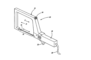
Fig. 1 is a perspective view of a hand-held powered coping saw according to
the present invention having a U-shaped frame, a handle, and a saw blade;
Fig. 2 is a cross-sectional view of the coping saw of Fig. 1 with portions of
the U-shaped frame broken away to show internal components and portions of the
handle broken away to show a rotary drum cam used to move the saw blade in a
reciprocating motion;
Fig. 3 is an enlarged, fragmentary top view of a distal blade retaining chuck;
Fig. 4 is a enlarged, fragmentary side view of the distal blade retaining
chuck
of Fig. 3.
Fig. S is an enlarged end view of the distal blade retaining chuck of Fig. 3.
Fig. 6A is a fragmentary, cross-sectional view of handle showing saw blade
in a furthermost proximal position.
Fig. 6B is a fragmentary, cross-sectional view similar to Fig. 6A showing the
drum cam rotated one-quarter revolution;
Fig. 6C is a fragmentary, cross-sectional view similar to Fig. 6B showing the
drum cam further rotated one-quarter revolution;
Fig. 6D is fragmentary, cross-sectional view similar to Fig. 6C showing the
drum cam further rotated one-quarter revolution; and
Fig. 7 is a perspective view of an alternative embodiment of the present
invention in the form of stationary powered table saw.
'
CA 02305352 2000-03-28
WO 99/17900 PCT/US98/20721
-4-
DETAILED DESCRIPTION OF THE PREFERRED EMBODIMENT
Fig. 1 shows an improved hand-held powered coping saw 10 of the present
invention having a U-shaped frame 12 defining a mouth or opening 14, a saw
blade
16 positioned within opening 14, and a handle 18 attached to frame 12. Handle
18
extends from U-shaped frame 12 away from opening 14 generally parallel to saw
blade 16. Handle 18 includes an electrical cord 20 to supply power to saw i0
and
a power switch 22 to switch power to saw 10 on and off. While coping saw 10 is
shown as a plug-in tool, one of ordinary skill in the art will recognize that
the saw
10 may also be designed as a battery operated, cordless tool with the battery
stored
within handle 18. Saw 10 further includes a thumb screw 24 used to tauten and
loosen saw blade 16. U-shaped frame 12 and handle 18 are generally made from a
rigid, durable material such as plastic or metal and must be strong enough to
withstand the normal stresses imposed on a coping saw during use.
For ease of explanation directions will be given in terms of "proximal" and
"distal". The proximal direction is the direction toward handle 18 as
indicated by
arrow P. The distal direction is the direction away from handle 18 as
indicated by
arrow D. When saw 10 is switched on, blade 16 is moved in alternating proximal
and distal directions within opening 14.
Fig. 2 is a cross-sectional view of saw 10 exposing components internal to U-
shaped frame 12 and handle 18. U-shaped frame 12 includes two generally
parallel
side members 26 and 28 and a frame cavity 30 extending fully about frame 12.
Positioned within frame cavity 30 are four rotatable pulleys 32, 34, 36, and
38 with
one pulley located near each end of side members 26 and 28. Three pulleys 32,
34,
and 36 are fixed with respect to U-shaped frame 12. The remaining pulley 38 is
a
tension pulley and is selectively moveable relative to U-shaped frame 12. Saw
10
further includes a threaded rod 40 having a first end 42 attached to a clevis
44 and
second end 46 inserted through an aperture 48 in U-shaped frame 12. Pulley 38
is
rotatably supported as clevis 44 is pinned through a center axis 50 of pulley
38.
Thumb screw 24 is threaded upon the second end 46 of rod 40. Thumb screw 24
may be turned in either direction to move pulley 38 relative to U-shaped frame
12. -
CA 02305352 2000-03-28
WO 99/17900 PCT/US98/20721
-5-
As such, thumb screw 24 may be used to tauten or loosen blade 16.
Alternatively,
one skilled in the art will recognize that other types of tension pulleys,
such as a
spring loaded tension pulley, may also be used in the present invention.
A flexible band 52 having a first end 54 and a second end 56 is entrained
about pulleys 32, 34, 36, and 38 and is routed within frame cavity 30.
Preferably,
band 52 is a steel cable or other similar material. First end 54 of band 52 is
operatively connected to a proximate blade retaining chuck 58 while the second
end
56 of band 52 is attached to a distal blade retaining chuck 60. Both first end
54 of
band 52 and proximate blade retaining chuck 58 are attached directly to a
reciprocating shaft 62. Alternatively, one of ordinary skill in the art will
recognize
that the both first end 54 of band 52 and reciprocating shaft 62 could be
attached
directly to proximate blade retaining chuck 58.
Saw 10 further includes saw blade 16 having a cutting edge 64. Saw blade
16 is retained between chucks 58 and 60 with cutting edge 64 directed away
from the
area enclosed by U-shaped frame 12. Saw blade 16 has a perpendicularly
projecting
peg 66 near each end of saw blade 16. To retain saw blade 16, each chuck 58
and
60 has an opening 67 in the end opposite band 52 adapted to receive one end of
saw
blade 16 and a retaining slot 68 adapted to receive one peg 66. Figs. 3, 4,
and 5 are
enlarged top, side, and end views respectively of distal blade retaining chuck
60 best
showing opening 14 and retaining slot 68. Slot 68 is angled so as to retain
peg 66
when saw blade 16 is pulled taut by band 52. Saw blade 16 may be removed from
chucks 58 and 60 when band 52 is loosened by way of thumb screw 24. One of
ordinary skill in the art will recognize that saw blade 16 may be retained
between
chucks 58 and 60 with other conventional fastening devices, such as-a screw.
Thumb
screw 24 may be turned in one direction to tauten blade 16 and band 52 should
band
52 stretch during use or turned in the opposite direction to loosen blade 16
and band
52 and thereby facilitate the replacement of blade 16.
Referring back to Fig. 2, handle 18 includes a hollowed portion 70 within
which a reciprocating drive 72 is supported. Reciprocating drive 72 includes a
motor
74 having a rotary output shaft 76, a drum cam 78 having a rotary input shaft
8~, and
a reciprocating shaft 62. Reduction gears 82 and 84 are fixedly secured to
output-
CA 02305352 2000-03-28
WO 99/17900 PCT/US98/20721
-6-
shaft 76 of motor 74 and input shaft 80 of cam 78 respectively. Reduction gear
82
is intermeshed with reduction gear 84. Reciprocating shaft 62 includes a pin
or, more
preferably, a cylindrical bearing 86 as shown which is slidably fixed within a
continuous groove 88 about cylindrical surface 90 of cam 78. One of ordinary
skill
in the art will appreciate that bearing 86 may be a conventional ball or pin
bearing.
Groove 8_8 spirals from one end of cam 78 to the opposite end of cam 78 in one-
half
revolution of cam 78. During the next one-half revolution of cam 78, groove 88
spirals from the opposite end of cam 78 back to its originating point thereby
forming
a continuous channel about the cylindrical surface 90 of cam 78. Thus, the
groove,
88 is generally spiraled, spiraling in one direction-toward a first end of the
drum cam
78 and then spiraling in the opposite direction toward the opposed end of the
drum
cam, wherein the spiral portions of the groove are interconnected by arcuate
or U-
shaped portions 92. As shown, the sidewalk of groove 88 are generally
perpendicular to cylindrical surface 90 to facilitate the movement of
cylindrical
bearing 86 in groove 88. The groove 88 in the drum cam 78 which receives the
bearing 86 thus smoothly translates rotary to reciprocating motion without
binding as
the saw blade 16 is driven through a workpiece. As will be understood by those
skilled in the art, the shaft 80 of the drum cam 78 may be coupled directly to
the
drive shaft 76 of the motor, thus eliminating gears 82 and 84 and the drum cam
78
may be utilized to translate rotary to reciprocating motion in other unrelated
applications. Multiple bearings, such as bearing 86, may also be inserted into
the
spiraled slot 88 in other applications to drive multiple reciprocating
elements. The
cam 78 may be formed of metal, such as stainless steel or friction resistant
plastics,
such as nylon. In the most preferred embodiment, cam 78 is supported by a
thrust
bearing.
The revolution of cam 78 is controlled by motor 74. The rotary movement
of output shaft 76 of motor 74 is transferred through reduction gears 82 and
84 to
input shaft 80 rotating drum cam 78 at a reduced speed relative to output
shaft 76.
As drum cam 78 rotates, bearing 86 slides within groove 88 thereby moving
shaft 62
in alternating and repetitive proximal and distal directions. An example of a
motor
CA 02305352 2000-03-28
WO 99/17900 PCT/US98/20721
_7_
which will function in the present invention is a 2700 RPM rated 7.2 volt DC
motor
manufactured by Black and Decker although any similar motor may be used.
One full cycle of reciprocating motion will now be shown in one-quarter
revolution increments with reference to Figs. 6A-D. In Fig. 6A is a
fragmentary,
cross-sectional view of handle 18 showing saw blade 16 in a furthermost
proximal
position. Fig. 6B is fragmentary, cross-sectional view similar to Fig. 6A
showing
drum cam 78 rotated one-quarter revolution. Reciprocating shaft 62 has been
slid in
a distal direction thereby moving saw blade 16 to an intermediate position.
Fig. 6C
is a fragmentary cross-sectional view similar to Fig. 6B showing drum cam 78
further
rotated one-quarter revolution. Reciprocating shaft 62 has been slid further
in a distal
direction thereby moving saw blade 16 to a furthermost distal position. Fig.
6D is
fragmentary, cross-sectional view similar to Fig. 6C showing drum cam 78
further
rotated one-quarter revolution. Reciprocating shaft 62 has now been slid in a
proximate direction thereby moving saw blade 16 back to the intermediate
position.
During the final one-quarter revolution of drum cam 78, reciprocating shaft 62
is slid
further in a proximate direction thereby moving saw blade 16 back to the
furthermost
proximate position as shown in Fig. 6A.
Fig. 7 is a perspective view of an alternative embodiment of the present
invention in the form of stationary powered table saw 110. Table saw 110
operates
in a similar manner as hand-held powered coping saw 10 described above. Like
numerals beginning with 100 indicate like or corresponding parts between
coping saw
10 and table saw 110. Frame 112 and handle 118 are generally made from a
rigid,
durable material such as metal or aluminum and must be strong enough to
withstand
the normal stresses imposed on a table saw during use.
Table saw 110 includes a base plate 192 to which frame 112 is attached.
Frame 112 is attached to base plate 192 such that blade 116 is oriented in a
vertical
direction. One of ordinary skill in the art will recognize that base plate 192
may be
attached to a supportive structure such as a bench or floor. In Fig. 7, base
plate 192
is shown bolted to a floor.
Table saw 110 further includes a table 194 pivotably attached to frame 112
generally perpendicular to blade 116. Table 194 has a bracket 196 which may be
-
CA 02305352 2000-03-28
WO 99/17900 PCT/US98/20721
_g_
pivotably attached with a pivot pin 198 to a boss 200 on frame 112. One of
ordinary
skill in the art will recognize that table I94 may be pivotably attached to
frame 112
with other adjustable fastening arrangements. Table 194 is generally made from
a
rigid, durable material such as plastic, metal, or aluminum and must be strong
enough
to support the typical type of work piece cut on a table saw.
Although a preferred embodiment of this invention has been disclosed, a
worker of ordinary skill in the art would recognize that certain modifications
would
come within the scope of this invention. For that reason, the following claims
should
be studied to determine the true scope and content of this invention.