Note: Descriptions are shown in the official language in which they were submitted.
CA 02305579 2005-10-05
METHODS AND APPARATUS FOR BLIND RIVETING
Blind rivets (i.e. rivets which can be installed by access to one side only of
the workpiece) are well known. Commonly a blind rivet comprises a tubular
shell
having an elongated shank with a preformed radially enlarged shell head at one
end
(the head end), in combination with a stem extending through the tubular shell
and
having a radially enlarged stem head at one end thereof (the head end)
adjacent the
other end (the tail end) of the shell shank. The other end portion of the stem
protrudes from the head end of the shell. The shell shank is inserted through
aligned apertures in the workpiece comprising the members to be riveted
together so
that the shell head abuts the near face of the workpiece and the tail end
portion of
the shell shank protrudes beyond the remote face (the blind face) of the
workpiece.
An increasing pulling force is then applied to the protruding portion of the
stem
relative to the shell, the reaction force being supported by the shell head,
so that the
stem head deforms the tail end portion of the shell shank radially outwards
and
axially towards the shell head, to form a blind head which abuts the blind
face of the
workpiece. The workpiece members are thus clamped together between the shell's
preformed head and its blind head. Usually the stem is then broken off flush
with,
or slightly inside, the head of the shell, at a breakneck preformed at the
appropriate
position along the stem. The breakneck breaking load is at a tension load
which is
greater than the load needed to completely form the blind head.
Such blind rivets and the method of using them are well known.
1
CA 02305579 2005-10-05
Blind rivets which provide a high level of static and dynamic joint strength
need to develop a high retained compressive force on the workpiece, between
the
preformed and blind heads, and to have a relatively laxge preformed head and
also a
blind side head which has a relatively large diameter in contact with the
blind face
of the workpiece, i.e. a relatively large blind side footprint. An example of
such a
blind rivet is described in GB 2 151 738 A, and is widely available under the
registered trademark HEMLOK.
One problem with such high joint-strength rivets in the past is that they have
been restricted in the amount of joint gap closure they can provide, i.e. the
amount
of gap initially present between the members to be joined, which the rivet can
successfully close up during installation in the members, is limited.
The present invention aims to overcome this problem, and aims to provide a
blind rivet which develops a large blind-side head footprint, an enhanced
sheet gap-
closing ability and also produces a large compressive force on the completed
joint.
Accordingly the invention provides a method of blind riveting to secure
together a
plurality of members with aligned apertures, using a blind rivet comprising a
tubular
shell and a stem extending through the tubular shell, the stem having a head,
the
stem head being adjacent one end of the shell and the other end of the shell
having
no preformed radially enlarged head or only a vestigial head of minimal radial
and
axial extent which is ineffective to exert any substantial clamping force on
the
members, which method comprises the steps of:
inserting the shell through the aligned apertures in the members, from the
near face of the near member, so that the aforesaid one end of the shell and
an
2
CA 02305579 2005-10-05
adjacent portion of the shell protrude beyond the remote face of the remote
member
and until the aforesaid other end of the shell is substantially level with the
near face
of the near member;
supporting the aforesaid other end of the shell with a supporting means and
applying a first force with respect thereto to the stem so as to pull the stem
head
towards the aforesaid other end of the shell and cause the end portion of the
shell
adjacent the said one end thereof to deform to substantially form a blind head
beyond the remote face of the remote member;
applying a second force to the near member with respect to the stem, to
push the near member towards the blind head until any gap between the members
is
taken up, with the portion of the shell adjacent the aforesaid other end of
the shell
then protruding from the near face of the near member;
and increasing the aforesaid first force so as to deform the aforesaid
protruding portion of the shell to form a near-side head, so that the members
are
clamped together between the blind head and the near-side head of the rivet
shell.
The completion of the formation of the blind head may overlap the start of the
formation of the near-side head.
The invention also provides blind riveting apparatus for carrying out a method
of
blind riveting which apparatus comprises:
supporting means for supporting the aforesaid other end of the shell;
gripping and pulling means for applying a first force to the stem so as to
pull
3
CA 02305579 2005-10-05
the stem head towards the aforesaid other end of the shell and cause the end
portion
of the shell adjacent the said one end thereof to deform to substantially form
a blind
head beyond the remote face of the remote member;
force-applying means for applying a second force to the near member with
respect to the stem, to push the near member towards the blind head until any
gap
between the members is taken up, with the portion of the shell adjacent the
aforesaid
other end of the shell protruding from the near face of the near member;
the aforesaid gripping and pulling means also being effective to thereafter
increase the aforesaid first force so as to deform the aforesaid protruding
portion of
the shell to form a near-side head, so that the members are clamped together
between the blind head and the near-side head of the rivet shell and in which
the
supporting means for supporting the aforesaid other end of the shell is of
substantially larger transverse dimensions than the shell with which the
supporting
means is intended to be used, whereby in use the supporting means also abuts
the
near member, and the force applying means for applying a second force to the
near
member is located transversely outside the supporting means.
The invention also provides a blind rivet for securing together a plurality of
members with aligned apertures, which blind rivet comprises:
a tubular shell and a stem extending through the tubular shell, the stem
having a head, the stem head being adjacent one end of the shell and the other
end
of the shell having no preformed radially enlarged head or only a vestigial
head of
minimal radial and axial extent which is ineffective to exert any substantial
clamping
force on the members;
4
CA 02305579 2005-10-05
the shell being such that, when it is inserted through the aligned apertures
in
the members so that the aforesaid one end of the shell and an adjacent portion
of the
shell protruding beyond the remote face of the remote member, and the
aforesaid
other end of the shell is supported and a progressively increasing force with
respect
thereto is applied to the stem so as to pull the stem head towards the
aforesaid other
end of the shell, the end portion of the shell adjacent the said one end
thereof
deforms to substantially form a blind head beyond the remote face of the
remote
member before any substantial deformation of the shell at or adjacent to the
aforesaid other end occurs the stem including a weakened portion, and the
shell
being such that after the formation of the blind head as aforesaid the part of
the shell
adjacent the aforesaid other end thereof is substantially radially enlarged to
form a
nearside head so that the members are clamped tightly together between the
heads,
and in which the progressively increasing force thereafter causes the stem to
fracture
at the weakened portion.
GB 613882 discloses a blind rivet having a shell without a preformed head,
and a method of riveting involving applying axial compression to the shell to
form
both the blind and near side heads. However the rivet is such that formation
of the
near side head is completed before formation of the blind side head begins.
Furthermore the rivet comprises only a tubular shell without a stem, the
placing tool
being provided with a reusable mandrel which is removed from the rivet shell
after
the latter has been completely deformed.
GB 511588 (Chobert), a divisional of GB 511,531, describes a tubular
riveting system for securing workpieces together. This earlier method employs
a
5
CA 02305579 2005-10-05
pull-through mandrel having an enlarged head. The riveting tool incorporates
an
inner sleeve around the mandrel, the sleeve having a smaller diameter than the
hole
in the workpieces and smaller diameter than the undeformed rivet. The
workpieces
are thus constrained against the force of the mandrel by the outer part of the
tool.
However, this prior art relates to pull-through riveting and is not, directly
applicable
to breakstem riveting. Furthermore, the dimensions of the riveting tool do not
allow space for a head to form on the rivet unless a countersink is provided
in the
workpiece nearest the tool.
Some embodiments of the present invention will now be described by way of
example and with reference to the accompanying drawings, in which:
Figures 1A, 1B and 1C show three successive stages in the deformation of
the shell of a first example rivet to form a blind head;
Figures 2A to 2E show five successive stages in the deformation of the shell
of a second example rivet to form a blind head, to close the workpiece members
together and to form a near side head;
Figures 3A to 3F show six successive stages in the action of deforming the
rivet of Figures 1A to 1C or 2A to 2E by means of a hydraulically-powered
riveting
tool;
Figures 4A to 4D show four successive stages in the deformation of a third
example rivet, and Figure 4E is an enlargement of part of Figure 4B;
Figures SA to SD show four successive stages (corresponding to Figures 4A
to 4D) in the deformation of a fourth example rivet; and
6
CA 02305579 2005-10-05
Figures 6A to 6D show four successive stages in the deformation of a fifth
example rivet.
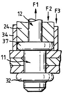
In the various Figures 1, 2, 3, 4, 5 and 6, like or corresponding parts of the
various rivets, and the placing tool, are indicated by like numerals for ease
of
understanding and comparison. Thus, all of the example rivets each comprises a
tubular shell 11 of low carbon steel and a stem 12 of medium carbon steel. The
stem has a radially enlarged head 13 at one end of slightly less diameter than
the
tubular shell. The stem and shell are assembled so that the stem head 13 is
adjacent
one face 21 (the tail end face) of the shell. The underhead face 14 is of
slightly
concavely dished, or part-conical, shape. The major portion 17 of the stem 12
is of
uniform diameter, on which the inner wall of the shell is a close fit.
However, the
portion 15 of the stem immediately adjacent the stem head 13 is of reduced
diameter, and this is joined to the remainder 17 of the stem by a transition
portion
16 of a diameter intermediate the portion 15 and the major portion 17 of the
stem.
_ The stem portion 17 is provided with a breakneck 18 in the well understood
way.
The shell 11 is provided with an external circumferential groove 19, which in
this
example rivet is about half way between the ends of the shell. On assembly of
the
shell and stem, the tailinost end portion 20 of the shell, which overlies the
stem
portions 15 and 16, is crimped or rolled inwardly into contact with those
portions,
as illustrated in Figure 1A, so that its inside and outside diameter tapers
inwardly.
The tail end face 21 of the shell abuts the head underface 14 as shown in
Figure IA.
The end 22 of the shell remote from the tail end face 21 is not preformed with
a
7
CA 02305579 2005-10-05
radially enlarged head, as is usual in blind riveting practice, but is of
substantially
uniform diameter and has a flat "head" end face 23.
Accordingly the tool employed to place the rivet (which tool is illustrated in
Figure 3) is provided with a nosepiece 24 (illustrated schematically in
Figures 1, 2,
4, 5 and 6) which has a flat annular anvil face 25. This face 25 is of
substantially
larger external diameter than the rivet shell 11. The tool is provided with
jaws to
grip the stem and pulling means, as is illustrated in Figure 3. The rivet stem
12 is
inserted into the nosepiece and the stem is gripped by the jaws. The rivet is
used to
join together two metal sheets 26, 27, there being a gap 28 between the near
sheet
26 and the remote or blind side sheet 27. The rivet is inserted into the
aligned
apertures 29, 29 in the sheets, in which the shell is a sliding fit, until the
anvil face
25 abuts the near face 30 of the near sheet. Thus the "head" end face 23 of
the rivet
shell is substantially level with the near face 30. The remote end of the
shell
including the shell circumferential groove 19 protrudes beyond the remote
sheet 27.
The tool is also provided with a sleeve 34 outside the nosepiece 24, the
purpose of which will be described later.
The tool is then actuated to apply a progressively increasing tension force F1
to the stem 12 with respect to the nosepiece 24 which takes up the reaction
force F2
against the end face 23 of the shell 11. The axial compression thus applied to
the
shell by the anvil face 25 and the underface 14 of the stem head 13, causes
the
tailmost portion 20 of the shell to buckle outwardly as shown in Figure 1B to
form a
bulb 31 between the groove 19 and the end 21 of the shell. Deformation in this
way
is promoted by weakening groove 19 in the shell, the tapered configuration of
the
8
CA 02305579 2005-10-05
portion 20 of the shell and the interengagement between the tail end face 21
of the
shell and the underhead face 14 of the stem head. However it will be apparent
to
the man skilled in the art of blind rivet design that there are alternative
and/or
additional ways of promoting deformation of the tailmost portion of the shell.
As the opposing forces F1 and F2 are increased, the bulb 31 of Figure 1B
further collapses axially until it forms a blind head 32 on the shell in the
form of a
folded flange, as shown in Figure 1C. This blind head is of relatively large
diameter and has a face 33 towards the near sheet 27 which is substantially
flat and
parallel to the face of the sheet, and is spaced apart from it. Note that
formation of
the blind head 32 does not rely upon its contact with the rear sheet 27
(although it
may contact it).
Figures 1A to 1C are intended to illustrate the construction and function of
the rivet 11, 12 insofar as the formation of the blind head 32 is concerned.
Further
increase of the tension force F1 will eventually cause further deformation of
the
rivet shell, in a manner similar to that which will now be described with
reference
to Figures 2 and 3.
The construction and function of the rivet and placing tool according to this
invention, with respect to closing the gap between the sheets, and the
formation of
the near side head, will now be described with reference to other examples.
Figures 2A to 2E illustrate a rivet which is substantially similar to that of
Figure 1, but is a modification thereof in that it has a physically longer
shell 11 to
provide a larger grip (i.e. the total thickness of sheets which the rivet can
join).
The rivet is used to join three sheets 26, 27 and 38, with gaps 28 between
adjacent
9
CA 02305579 2005-10-05
sheets. The rivet shell is appropriately longer, so that when the end face 23
of the
shell is level with face 30 of the near sheet 26, the external groove 19 of
the shell is
also beyond the rear face of the rear sheet 27 (Figure 2A corresponds to
Figure 1A).
Axial compression of the rivet shell forms a blind head 32 shown in Figure 2B
(which corresponds to Figure 1 C) in the same way as described with reference
to
Figure 1.
Up to the formation of the blind head 32, the external sleeve 34 of the tool
has played no part in the process. In Figure 1 it is shown with its end face
35
remaining slightly retracted from the anvil face 25 and near face 30 of the
sheets,
whereas in Figure 2 its end face 35 is level with the anvil face 25. In both
cases the
sleeve 34 has so far not moved with respect to the nosepiece 24. However, once
the
blind head 32 has been formed, the blind head can be used to pull the sheets
26, 34,
27 together. This is done by transferring the reaction force to the pull F1 on
the
stem from the nosepiece 24 to the sleeve 34. Preferably this transfer is
progressive.
The result is that, the rivet stem 12 is retracted with respect to the sleeve
34, thus
compressing the sheets between the shell blind head 32 and the sleeve end face
35
which abuts the near face 30 of the near sheet 26.
If F1 is the tension force on the stem 12, F2 is the reaction force applied by
the nosetip anvil face 25 to the head end face 23 of the rivet shell, and F3
is the
reaction force applied by the sleeve end face 35 to the front sheet 26, then
at any
position substantially F1 = F2+F3, assuming that no resultant force is
supported
by the sheets. The "head" end portion of the rivet shell 11 progressively
emerges
from the front sheet 26, with the nosetip 24 being retracted in unison with
the rivet
CA 02305579 2005-10-05
stem. Eventually the three sheets 26, 38, 27 are pulled into contact with each
other
so that the gaps 28,28 have disappeared, as in the position illustrated in
Figure 2C.
It is now required to form a near side head on the rivet shell, i.e. to
radially
enlarge the "head" most end of the shell.
The placing tool is further actuated so that, whilst retaining the clamping
force on the sheets between the blind head 32 and the sleeve 34, the force F2
on the
nosepiece 24 is increased. In this example, the shell 11 is provided with a
second
external circumferential groove 36, which is positioned so that it lies
substantially
level with the near surface 30 of the near sheet 26, as illustrated in Figure
2C. This
groove 36 has less depth than the shell tail end groove 19, so that the head
end
groove 36 provides less weakening to the shell than the tail end groove 19.
Under
the increasing axial compression on the sleeve, the "head" end portion of the
sleeve,
between the groove 36 and the end face 23, buckles outwardly to form first a
bulb
and then a folded flange (like the blind head 32) which provides a near side
head 37,
as illustrated in Figure 2D. Further increase in the tension force F1 on the
stem
causes it to break at the break neck 18 (not shown in Figures 2A to 2D);
leaving the
installed rivet to form a joint between the sheets 26, 38 and 27, as
illustrated in
Figure 2E.
Note that the clamping or compression load on the sheets between the sleeve
34 and the already formed blind head 32, whilst the near side head 37 is being
formed, is not reduced by the force used in deforming the rivet shell to form
the
near side head. The near side head 37 is formed, clamping the sheets between
it
and the blind head 32, whilst the sheets are already clamped together between
the
11
CA 02305579 2005-10-05
sleeve 34 and the blind head 32. The result is that the riveted joint provides
a
higher retained clamping force on the sheets than if similar deforming forces
were
used to form the blind head on an equivalent blind rivet with a preformed near
side
head. Thus the riveted joint provided by the present invention is stronger.
One form of suitable riveting tool is shown schematically in Figures 3A to
3F. Referring first to Figure 3A, which shows the tool before a rivet is
inserted in
it, the tool 41 comprises a generally cylindrical main body 42 containing an
upper
hydraulic cylinder 43 and a lower hydraulic cylinder 44, the upper cylinder 43
being
approximately twice as long as the lower cylinder 44. The two are separated by
an
annular wall 45 from which projects downwardly a cylindrical extension 46, the
lower end of which protrudes from the bottom of the body 42 to provide the
tool
nosepiece 24 with the flat annular anvil face 25.
The tool sheet-contacting sleeve 34 surrounds the nosepiece 24, for axial
movement with respect to both the tool body 42 and the nosepiece 24. The upper
end of the sleeve 34 has an outward annular flange 47, which reciprocates in
the
lower hydraulic cylinder 44 and is urged upwardly by a coil compression spring
48.
A stop (not shown) prevents the flange 47 from seating on the annular wall 45,
leaving a space between the flange 47 and wall 45 connected by means of a port
49
to a source of variable hydraulic pressure (not shown).
The tool body 42 also contains a pulling piston 51 which can reciprocate
with respect to the tool body. The piston 51 comprises essentially a
cylindrical
piston, which at about the mid point of its length has an outward flange 52
which is
a sliding fit in the upper hydraulic cylinder 43. The flange is urged
downwardly by
12
CA 02305579 2005-10-05
a coil compression spring 53, and is prevented from seating on the annular
wall 45
by means of a stop (not shown), leaving a space between the flange 52 and wall
45
which is connected by means of a port 54 with a source of variable hydraulic
pressure (not shown). The lower end part of the extension 46 forming the
nosepiece
24 contains the usual jaw assembly 55 for gripping rivet stems and pulling
them
with respect to the anvil face 25, and will not be described further.
Clearly increasing the hydraulic pressure supplied to the lower port 49 drives
the sleeve 34 downwards against the urging of spring 48, and increasing the
hydraulic pressure supplied to the upper port 54 drives the piston 51 and jaw
assembly 55 upwards against the urging of spring 53. These hydraulic pressures
are
controlled in a conventional way by convenient known means, in order to move
the
sleeve 34 and jaw assembly 55 as required and to apply the required force to
each of
them in order to place a rivet in the way previously described.
In use, the stem 12 of a rivet is inserted into the nosepiece, where it is
gripped by the jaw assembly 55 in the usual way, with "head" end of the rivet
shell
11 in contact with the anvil face 25 as previously described. The tool is then
moved
to insert the rivet shell through the aligned holes 29 in the sheets to be
riveted, until
the anvil face contacts the near face 30 of the near sheet 26. This is the
portion
illustrated in Figure 3B. Figures 3B to 3F show a rivet similar to that shown
in
Figure 1 being placed to rivet two sheets 26, 27 together, Figure 3B
corresponding
to Figure 1A. Figures 3B to 3F show the near sheet 26 as being in a fixed
position,
and the remote sheet 27 being pulled up towards it.
13
CA 02305579 2005-10-05
With no hydraulic pressure applied to the sleeve port 49, a progressively
increasing hydraulic pressure is applied to piston port 54, thus pulling the
rivet stem
into the nosepiece whilst holding the rivet shell against the anvil face and
forming
the blind head 32 (Figure 3C) as previously described. Whilst maintaining the
hydraulic pressure at piston port 54, hydraulic pressure to the sleeve port 49
is
progressively increased, driving the sleeve 34 downwards to abut the part
sheet 26
and then pulling on the blind head 32 to pull the sheets 27, 26 together
(Figure 3D)
and apply clamping pressure to the sheets 26 and 27. The nosepiece 24 and tool
body 42 move upwards with the rivet stem 12 and rivet shell 11 (accommodating
similar amounts of movement of the body of a conventional hand-held blind
riveting
tool is common practice). Whilst at least initially maintaining the hydraulic
pressure
to the sleeve port 49, the hydraulic pressure to the piston port 54 is
progressively
further increased, thereby to drive the nosepiece 24 and anvil face 25
downwards,
with respect to the rivet stem, thus forming the near side head 37 as
previously
described (Figure 3E). During the latter part of this process the hydraulic
pressure
supply to the sleeve port 49 may be progressively reduced, so as not to
overstress
the stem at the breakneck 18.
The hydraulic pressure to the sleeve port 49 is then reduced sufficiently to
allow the force of the spring 48 to push the sleeve 34 upwards and withdraw it
from
contact with the near sheet 26, so that all the reaction to the pulling force
exerted on
the rivet stem 12 by the pulling jaw assembly 55 is taken up through the rivet
head
37, as illustrated in Figure 3F. The hydraulic pressure to the piston port 54
is then
increased until the stem breaks at the breakneck, leaving the riveted joint.
14
CA 02305579 2005-10-05
Figures 4A to 4E illustrate another example rivet and method of riveting
incorporating two possible alternative features. Firstly, where rivets are
likely to be
used in oversized holes (i.e. at least some of the holes are likely to be of
slightly
larger diameter than the recommended size), the radial expansion of the shell
to
form the blind head 32 can be configured so that the part 56 of the shell
immediately
adjacent the blind head flange 32 is also somewhat radially expanded, as
illustrated
in Figure 4A. When the blind head is then pulled up against the remote sheet
27 to
close the gap 28 and clamp the sheets 26, 27 together between the sleeve 34
and
blind head 32, as previously described, this radially enlarged part 56 is
forced into
the remote end of the hole 29 in the remote sheet 27, to produce localised
hole fill,
as illustrated in Figure 4B, providing enhanced sealing of the joint. As
illustrated in
enlarged Figure 4E, the edge of the remote sheet 27 around the hole may bite
into
the part 56 of the shell.
Secondly, an alternative near side head form can be used. The anvil face of
the nosepiece 24 is provided with a concavely curved profile as illustrated at
57 in
Figures 4A to 4C. When the uppermost part of the shell 11 is pulled against
the
concave anvil face 54 with sufficient force, it is rolled radially outwardly,
as
illustrated in Figure 4C, to form a near side head 58. This is bent downward
by the
concave anvil face 57 until the outer periphery of the underside of the head
58 abuts
the near face 30 of the near sheet 26, as illustrated in Figures 4C and 4D.
The
uppermost part of the rivet shell is preferably suitably configured to co-
operate with
the concave anvil face 57 in this mode of deformation.
CA 02305579 2005-10-05
In certain applications of blind riveting, it is found more convenient first
to
insert the blind rivet in the hole in the sheets, and then to apply the tool
to install the
rivet. This method of operation is facilitated by the example rivet
illustrated in
Figures SA to SD, in which the "head" end of the rivet shell is provided with
a
vestigial head 59 of minimal radial and axial extent, which is sufficient to
engage
the near sheet 26 and prevent the rivet from falling through the holes 29, 29
in the
sheets, but would be ineffective to exert any substantial clamping force on
the sheets
26, 27. Installation of the rivet including formation of the near side head
takes
place in the same way as previously described. Figures SA to SD illustrate the
formation of a rolled-over near side head 57 as in Figures 4A to 4D, but
equally the
vestigial head 59 could be used to produce the bulbed near side head form
illustrated
in Figure 2D.
Another example rivet and method is illustrated in Figures 6A to 6D, for use
in making joints between sheets 26, 27 which are substantially thinner and
therefore
weaker, than the sheets 26, 27 referred to previously. In this case the force
applied
to the sheets 26, 27 between the blind head 32 and the tool sleeve 34 (which
has a
diameter much larger than the rivet shell 11 and approximately equal to that
of the
blind head 32) is sufficient to deform both the thin sheets in the annular
region
between the rivet shell 11 and the sleeve 34 into a part conical dished or
dimpled
form as illustrated at 61 in Figures 6B, 6C to 6D. The near side head 37 then
abuts
the top of this dimple. In order to facilitate deformation of the sheets in
this way,
the rivet is configured so that the blind head 32 has a convex shape on its
side
nearer the remote sheet 27, as illustrated in Figure 6.
16
CA 02305579 2005-10-05
The methods of riveting, and the rivets, described in the foregoing examples
are also advantageous in that it is simpler and less expensive to manufacture
a blind
rivet without a preformed near side head (or with only the vestigial head
illustrated
in Figures SA to SD).
The invention is not restricted to the details of the foregoing examples.
17