Note: Descriptions are shown in the official language in which they were submitted.
CA 02305788 2000-03-31
WO 99/17923 PCTNS98/20640
PACKING MATERIAL PRODUCT AND METHOD
AND APPARATUS FOR MAKING, MONITORING
AND CONTROLLING THE SAME
This application is a continuation-in-part of co-owned U.S. Patent Application
Serial Nos. 08/482,015 and 081279,149, filed June 7, 1995 and July 22, 1994,
respectively, both entitled, pCushioning Conversion Machine" and incorporated
herein by this reference.
FIELD OF THE INVENTION
The present invention relates to a resilient packing material or the like and
to
the method and apparatus for making the same. More particularly, this
invention
relates to an apparatus and method having a controller which can be used to
monitor a number of different machines and to record and perform machine
diagnostics.
Styrofoam pellets or peanuts are commonly used within the wholesale and
retail industries as bulk packaging material. The peanuts are used to position
a
product away from the interior sides of a container and fill the empty space
located
therebetween. The peanuts are intended to protect the packaged product against
the impact of a blow or other mistreatment.
Dispensing styrofoam peanuts does not require a great degree of
sophistication. The peanuts are simply gravity fed from large retainer bins
into the
empty spaces within a packaging container. Use of styrofoam peanuts, however,
has many drawbacks. For example, if styrofoam peanuts are used to protect a
heavy object placed within a container, and such package is jostled or shaken,
the
object usually gravitates toward the bottom of the container and the peanuts
float
upward. Eventually the object comes to rest against the base or side of the
container and damage to the object may occur. The light weight of the
styrofoam
peanuts also allows them to be easily blown by the wind and scattered. The
-1-
CA 02305788 2000-03-31
WO 99/17923 PCTIUS98/20640
styrofoam peanuts also create static electricity, causing the peanuts to cling
to the
protected articles after the articles are removed from their containers.
Further, the
peanuts may create an electrostatic discharge (ESD) which can cause damage to
sensitive electronic components.
Of particular concern, styrofoam peanuts are extemely difF~cult to dispose of
and destroy after use. In fact, because of the extensive use of this
nonbiodegradable product, which emits toxic gases if burned, styrofoam peanuts
present a major threat to the environment and are being banned from an
increasing
number of communities. Styrofoam peanuts are also dangerous to children and to
wildlife who often mistake them as food and consequently ingest them.
Styrofoam
peanuts are not digestible and are a major source of tracheal blockage in
children.
Other packaging filler materials, such as shredded paper, have also been
used. Shredded paper, however, usually lays flat within the container and a
large
amount of paper is required to provide the bulk needed to fill the voids and
to protect
the contained object. To provide such a large amount of shredded paper is
often
cost prohibitive and, following ifs use, such voluminous amounts of paper must
be
disposed. In addition, the shock absorbency of flat, shredded paper is
minimal.
U.S. Patent 5,403,259, which is hereby incorporated by reference, is directed
toward an apparatus and method for rapidly producing large quantities of bulk
packaging material comprising folded and crimped, interlocking strips of sheet
material which may be used as resilient padding to cushion and prevent heavier
objects from gravitating toward the bottom or sides of a container. The
apparatus
and method provides for the production of selectable lengths, the smaller
lengths
capable of being gravity fed into containers to fill voids and larger lengths
capable of
being wrapped around a product to provide a secure, protective cushion. The
method and apparatus is also operable to produce such folded and crimped,
interlocking strips of sheet material in selectable colors andlor controlled
color
combinations for decorative and aesthetic purposes. Furthermore the apparatus
_2_
CA 02305788 2000-03-31
WO 99/17923 PCT/US98/20640
and method allows for the manufacture of such strips from biodegradable
material,
such as pulp material (i.e., paper, cardboard, or the like).
Due to the increased popularity of paper protective packaging material,
additional, automated control mechanisms to operate andlor monitor such
packaging material construction, would be desirable. Consequently, it would be
desirable to provide a single controller which could monitor a variety of
machine
types without substantial adjustments or modifications to the controller. It
would also
be desirable for a controller to collect and to store diagnostic information
and to
perform enhanced and automated packaging functions.
SUMMARY OF THE INVENTIOd
The present invention provides a packing product and method and apparatus
for making the same having a monitoring system including a controller suitable
for
use in monitoring and providing diagnostics for one or more conversion
machines
with little or no change required of the controller. The controller associated
with the
one or more conversion machines communicates with various sensors and
measuring devices to greatly increase the information available to a user or
technician either local to or remote from the one or more conversion machines
for
recording machine and stock material usage and aiding in diagnostic evaluation
and
other functions.
The controller monitors one or more operating characteristics of the one or
more conversion machines. Exemplary operating characteristics include
inventory
data relating to a roll of sheet material being used, data relating to a
treatment of the
sheet material, a color of the sheet material being used and a quantity of
sheet
material that has been converted. Additional, exemplary operating
characteristics
that may be monitored by the monitoring system include a performance quality
of a
shredding device, a status of the shredding device, a temperature of one or
more
portions of the conversion machine, a pressure exerted within a restricting
region, a
-3-
CA 02305788 2000-03-31
wo ~n ~~3 Pcnus9snosao
shear force exerted by a transverse cutting element and container data for
dispensing of a converted product from the conversion machine into a
container.
According to one aspect of the present invention, a cushioning conversion
machine having a controller for monitoring the cushioning conversion machine
is
disclosed. The controller is suitable for use in a variety of different
configurations of
the cushioning conversion machine with little or no change required of the
controller.
The controller includes a number of output ports for controlling the function
of the
cushioning conversion machine regardless of the cutting assembly employed or
the
operation mode selected for the controller. The cushioning conversion machine
preferably includes a controller which communicates with various sensors and
measuring devices to greatly increase the information available to the
controller for
recording and aiding in diagnostic and other functions.
In accordance with another aspect of the present invention, an apparatus and
method for rapidly producing and monitoring large quantities of bulk packaging
material comprising folded and crimped, interlocking strips of sheet material
is
disclosed. In this particular embodiment of the present invention, sheet
material is
cut into a plurality of longitudinal strips. The advancement of the strips is
restricted
to cause the strips to fold against themselves in a relatively controlled
manner,
thereby repetitively folding, crimping or creasing each strip. The monitoring
system
of the present invention is operable to monitor one or more of the operating
characteristics of the apparatus and method and provide diagnostic information
to a
user either local to or remote from manufacturing site.
The monitoring system, via the controller, is operable to monitor each of the
above discussed features of one or more conversion machines as well as other
conversion machine operating characteristics. For example, the controller is
operable to monitor the pressure exerted by the accumulated body of strips to
ensure that the shredding device does not become jammed. In addition, the
controller monitors the status of the shredding blades to ensure that the
blades are
CA 02305788 2000-03-31
WO 99/17923 PCT/US98I20640
properly aligned and maintained. Further, the controller may monitor the
shearing
force exerted by a shearing device used to cut the elongated strips into strip
segments, (if employed). Further still, the controller is operable to monitor
the
amount of total paper andlor the various amounts of different colored paper
used for
inventory control and/or marketing purposes. Lastly, the controller is
operable to
monitor the timing of machine operation and the stability or vibrational modes
of the
conversion machine to ensure that any wear or faiture mechanisms are pro-
actively
addressed before a machine failure occurs. The controller is operable to
monitor
one or more of the above conversion machine characteristics and provide visual
andlor audible indications of such characteristics via a display.
The controller may be utilized local to one or more conversion machines by a
user or alternatively they may be monitored remotely via a data communication
port
and a communication apparatus such as a modem. With remote monitoring,
multiple conversion machines at various locations can be easily and
efficiently
monitored.
To the accomplishment of the foregoing and related ends, the invention
comprises the features hereinafter fully described and particularly pointed
out in the
claims. The following description and the annexed drawings set forth in detail
certain illustrative embodiments of the invention. Theses embodiments are
indicative, however, of but a few of the various ways in which the principles
of the
invention may be employed. Other objects, advantages and novel features of the
invention will become apparent from the following detailed description of the
invention when considered in conjunction with the drawings.
BRjEF DESCRIPTION OF THE DRAWINGS
In the annexed drawings:
Figure 1 is an illustration of a cushioning conversion machine;
Figure 2 is a block diagram of a universal controller for a cushioning
conversion machine;
_5_
CA 02305788 2000-03-31
WO 99/17923 PCT/US98/20640
Figures 3 through 8 are electrical schematic diagrams of an embodiment of
the universal controller;
Figure 9 is a block diagram of a controller for a cushioning conversion
machine with enhanced diagnostic capabilities;
Figure 10 is a front view of a length measuring device and other relevant
portions of the cushioning conversion machine;
Figure 11 is a side view of the length measuring device;
Figure 12 is a block diagram of a controller including a code reader for
reading information from stock paper and a container probe for determining
packaging information from a container to which packaging is to be added;
Figure 13 is a block diagram of a fault tolerant cushioning producing network;
Figure 14 is an illustration of fwo cushion producing machines positioned at
either end of a conveyor and communicating via a network;
Figure 15 is a simplified, isometric view of strips of shredded paper as found
in the prior art;
Figure 16 is a simplified, isometric view of a plurality of folded, crimped,
interlocking strips of shredded sheet material as produced by the present
invention;
Figure 17 is a simpl~ed, isometric view of a plurality of folded, crimped,
interlocking strip segments of shredded sheet material which is a product of
the
present invention;
Figure 18 is a partial, cross-sectional, side elevational view of one
embodiment of the present invention, wherein a conversion machine is monitored
by
a universal controller and a plurality of sensors;
Figure 19 is a partial, cross-sectional, side elevational view of the
apparatus
shown in Figure 18, wherein the gate of the conversion machine is urged away
from
its closed position;
Figure 20 is a fragmentary, sectional side elevational view of a controllable
feeder apparatus according to one embodiment of the present invention;
CA 02305788 2000-03-31
WO 99/17923 PCT/US98/20640
Figure 21 is a side fragmentary, sectional side view of a controllable feeder
apparatus that is integrated with the conversion machine;
Figure 22 is a block diagram of the controller according to an embodiment of
the present invention; and
Figure 23 is a block diagram of the controller coupled to a remote processor
according to another embodiment of the present invention.
DETAILED DESCRIPTION OF THE INVENTION
The present invention provides a packing product and method and apparatus
for making the same having a monitoring system including a controller suitable
for
use in monitoring and providing diagnostics for one or more conversion
machines
with tittle or no change required of the controller. The controller associated
with the
one or more conversion machines also communicates with various sensors and
measuring devices to greatly increase the information available to a user or
technician either local to or remote from the one or more conversion machines
for
recording machine and stock material usage and aiding in diagnostic evaluation
and
other functions.
The controller monitors one or more operating characteristics of the one or
more conversion machines. Exemplary operating characteristics include
inventory
data relating to a roll of sheet material being used, data relating to a
treatment of the
sheet material, a color of the sheet material being used and a quantity of
sheet
material that has been converted. Additional, exemplary operating
characteristics
that may be monitored by the monitoring system include a performance quality
of a
shredding device, a status of the shredding device, a temperature of one or
more
portions of the conversion machine, a pressure exerted within a restricting
region, a
shear force exerted by a transverse cutting element and container data for
dispensing of a converted product from the conversion machine into a
container.
Further, the controller may store machine information such as a serial number,
software revision number and date, physical site location, customer data and'a
_7_
CA 02305788 2000-03-31
WO 99/17923 PCTIUS98/20640
conversion machine number or identifier. Other, additional information, as
needed
or desired, may also be evaluated, monitored and/or stored.
The present invention is applicable to many types of packaging material
conversion machines. For example, with reference to the drawings and initially
to
Figure 1, there is shown a cushioning conversion machine 10 including a frame
12
upon which the various components of a conversion assembly 14 are mounted and
a controller 16 (illustrated schematically) for controlling the machine
including the
components of the cushioning assembly. The frame 12 includes a stock supply
assembly 18 which holds a roll of stock for conversion by the conversion
assembly
14 into a cushioning material. The conversion assembly 14 preferably includes
a
feed assembly 19 which includes a forming assembly 20 and a gear assembly 22
powered by a feed motor 24, a cutting assembly 26 powered by, for example, a
cut
motor 28 selectively engaged with the cutting assembly by an AC solenoid
driven
clutch 30 and a post cutting constraining assembly 32.
During the conversion process, the forming assembly 20 causes the lateral
edges of the stock material to roll inwardly to form a continuous strip having
two
lateral pillow like portions and a central band therebetween. The gear
assembly 22
performs a "pulling" function by drawing the continuous strip through the nip
of two
cooperating and opposed gears of the gear assembly thereby drawing stock
material through the forming assembly 20 for a duration determined by the
length of
time that the feed motor 24 rotates the opposed gears. The gear assembly 22
additionally performs a "coining" or "connecting" function as the two opposed
gears
coin the central band of the continuous strip as it passes therethrough to
form a
coined strip. As the coined strip travels downstream from the gear assembly
22, the
cutting assembly 26 cuts the strip into sections of a desired length. These
cut
sections then travel through the post-cutting constraining assembly 32.
The controller 16 is preferably "universal" or capable of use in a number of
differently configured cushioning conversion machines without requiring
substantial
_g_
CA 02305788 2000-03-31
WO 99/17923 PCT/US98I20640
change to the controller. Accordingly, one configuration of a universal
controller 16
can thus be manufactured for a variety of different cushioning conversion
machines.
The assembly technician then need not adapt the controller 16 to a specific
configuration of the cushioning machine, such as when one of the particular
cushioning machines is adapted to use an air powered cutting assembly, a
direct
current powered solenoid cutting assembly, or a motor driven cutting assembly.
The
capability of the universal controller to control differently configured
machines
reduces assembly time, reduces assembly cost since the labor cost in
specifically
configuring a controller often outweighs the cost of assembling unused
electrical
components in the controller and reduces the possibility of assembly error.
Moreover, repair of the machine is facilitated since training of the repair
technician is
minimized and since an inventory of universal controllers for use in a variety
of
cushioning machines can be maintained.
An exemplary universal controller 16 is illustrated in Figure 2 and includes a
number of different output ports 36, 38, 40, 42, 44 and 46 devoted to
providing a
control signal from a microprocessor 48 to a DC shear solenoid, an AC control
solenoid, a cut motor, a feed motor, a counter and a spare port, respectively,
in
accordance with a number of inputs 50. While the microprocessor 48 is
illustrated
and described herein as a single device, it is noted that microprocessor 48
may be
embodied as a number of microprocessors or control units of the same type or
as
different microprocessors adapted for performing certain functions. The DC
shear
solenoid, controlled by the microprocessor 48 through DC shear solenoid port
36,
powers a cutting blade positioned at the output of a cushioning conversion
machine.
When the DC shear solenoid is provided power by a control signal sent through
the
port 36, the solenoid actuates a cutting blade to force the blade through the
dunnage to make a cut. One machine employing a cutting assembly powered by a
DC solenoid is marketed by Ranpak Corp. under the name PadPak~ and is
-9-
CA 02305788 2000-03-31
WO 99/17923 PCT/US98/20640
disclosed in U.S. Patent No. 4,968,291 which is incorporated herein by this
reference.
The AC control solenoid port 38 controls an external AC solenoid which is
typically used in conjunction with either an air-powered cutting assembly or a
motor
powered cutting assembly. When a cushioning conversion machine including the
universal controller 16 employs an air-powered cutting assembly, the cutting
assembly uses the AC solenoid to control the supply of pressurized air to an
air
cylinder which drives a cutting blade to shear off a section of dunnage fed
through
the machine. A cushioning conversion machine employing an air-powered cutting
assembly is marketed under the name PadPak~ by Ranpak Corp. and disclosed in
U.S. Patent No. 4,968,291 which has been incorporated herein above. The AC
control solenoid port 38 may also be used to control an AC solenoid which acts
to
couple the direct drive cut motor 28 to the cutting assembly 26 via the clutch
30 to
drive a cutting blade through a cutting stroke to cut a section of dunnage
material
fed through the machine. One such machine is marketed by Ranpak Corp. under
the name AutoPad~ and is disclosed in U.S. Patent No. 5,123,889 which is also
incorporated herein by this reference. In this embodiment of a cushioning
conversion machine, the cut motor port 40 is used to supply a signal to the
cut motor
28 to ensure that the cut motor is running when a cut is desired.
In any of the embodiments of a cushioning conversion machine described above,
. there is employed some means for moving the paper material through the
machine
to create the dunnage material. The PadPak~ and AutoPad~ machines referenced
above employ the feed motor 24 which turns the enmeshed gears 22 that grip the
paper stock and feed it through the machine where the appropriate conversion
of the
sheet-like stock to a dunnage product and the cutting of the dunnage product
into
appropriate lengths takes place. The universal controller 16 controls the feed
motor
24 through the feed motor port 42. When it is desired that an appropriate
length of
paper be fed through the cushioning conversion machine by the feed motor 24,
the
-10-
CA 02305788 2000-03-31
WO 99/17923 PCT/US98/Z0640
microprocessor 48 sends a_signal through the feed motor port 42 which causes
power to be supplied to the feed motor for as long as the signal is present.
When
the microprocessor 48 has determined that the desired length of paper stock
has
been fed through the machine 10, the signal is disabled causing the feed motor
24
to stop and the supply of paper through the machine to stop. At this time the
microprocessor 48 will determine, based on the position of the mode selection
switch 52 and the condition of the input signals 50, whether to initiate a cut
of the
dunnage material fed through the machine 10, as is described more fully below.
Depending upon the embodiment of the cushioning conversion machine 10,
the universal controller 16 may also use the counter port 44 to control a
counter
which keeps track of the machine usage or a spare port 46 which can be used to
provide command signals to some other device.
While the universal controller 16 includes the output ports 36 through 46 for
the control of the feed motor 24 and a variety of cutting assemblies, in most
applications less than all of the ports will be used. For example, when the
universal
controller 16 is used to control a cushioning conversion machine having a DC
shear
solenoid powered cutting assembly, such as the PadPak~ machine mentioned
above, the DC shear solenoid port 36 is used while the AC control solenoid
port 40
and the cut motor port 16 will not be used. When the universal controller 16
is used
to control a machine 10 having an air powered cutting assembly, the AC control
port
38 is employed to control the AC control solenoid, and the DC shear solenoid
port
36 and the cut motor port 40 may be unused. Similarly, when the universal
controller 16 is used in conjunction with a cushioning conversion machine
using the
cut motor 28 to actuate the cutting assembly 26, such as the AutoPad~ machine
mentioned above, the AC control solenoid post 38 and cut motor port 40 will be
used
to control and power the cutting assembly 26 while the DC shear solenoid port
36
will be unused. Preferably, the microprocessor 48 will more or less
simultaneously
cause appropriate signals to be sent to each of the respective output ports
36, 38,
-11-
CA 02305788 2000-03-31
WO 99/17923 PCT/US98/20640
40 regardless of the actual cutting assembly employed with a machine. In this
way
the microprocessor 48 does not need to be informed of this aspect of the
configuration of the machine and the cutting assembly 26 connected to a port
will
thus be the one that responds to a signal sent from the microprocessor without
the
microprocessor having to distinguish which type of cutting assembly is
employed.
Control of the various devices, such as the DC shear solenoid and the cut
and feed motors, is performed by the microprocessor 48 in accordance with
certain
inputs 50 which are indicative of the operating condition of the cushioning
conversion machine 10 and certain events which may have been sensed. The
inputs 50 also include an indication of the operating mode for the cushioning
conversion machine selected through the mode selection switch 52, such as a
rotary
switch. The mode selection switch 52 includes a number of settings
corresponding
to different operating modes, for example, keypad mode, electronic dispensing
system mode, automatic cut mode, feed cut foot switch mode, and automatic feed
mode. The mode setting of the controller 16 as well as a number of error
signals
may be displayed as alphanumeric codes on the display 54. For example, a
display
code of'1' may indicate to an operator that the machine 10 is operating in the
automatic feed mode, while a display of "A" may indicate that an error has
occurred
in the buttons used to manually command a cut.
The keypad mode is for cushioning conversion machines which are equipped
with a keypad through which an operator may input the length of each pad which
she desires the machine to produce by depressing the appropriate key on the
keypad. In this mode, regardless of the cutting assembly employed, the
microprocessor 48 provides a signal to the feed motor through the feed motor
port
42 to feed material through the machine for the appropriate length of time to
provide
dunnage of the length which the operator selected through the keypad. The
keypad
buttons are preferably pre-programmed so that each button corresponds to a
particular cut length. For example, if an operator pushes button 12 on the
keypad,
-12-
CA 02305788 2000-03-31
WO 99/17923 PCTlUS98I20640
and this button was preprogrammed to correspond to a length of 12 inches, the
microprocessor 48 will signal the feed motor 24 and turn the feed motor on for
a
length of time that equates to 12 inches of dunnage material being fed out,
and then
the microprocessor will disable the feed motor. Upon completion of the dunnage
material of the selected length being fed through the machine, the
microprocessor
48 automatically commands the cutting assembly 26 employed, through the output
ports 36, 38, and 40, to perform a cut. The microprocessor 48 then waits for
the
next key on the keypad to be depressed and repeats the process to produce a
length of dunnage corresponding to the key depressed.
When the electronic dispensing system {EDS) mode setting is selected on the
mode selection switch 52, an external electronic dispensing sensor is employed
to
detect the presence or absence of a dispensed length of dunnage material. The
infom~ation as to the presence or absence of dunnage material is provided to
the
microprocessor 48 through one of the inputs 50. If the sensor detects that
there is
no dunnage material left at the cutting area of the machine, this information
is
passed to the microprocessor 48 which will send a signal to the feed motor 24
through the feed motor port 42 to feed out a certain length of material. The
length of
material to be fed through the machine 10 is determined by the setting of a
thumb
wheel, which is described below, as reported to the microprocessor 48 over one
of
the inputs 50. Once material is fed through the machine 10 and emerges at the
cutting exit, the electronic dispensing sensor will report to the
microprocessor 48 the
presence of the dunnage material at the cutting exit of the machine. After the
complete length of material has been fed through the machine 10 by the feed
motor
24, the microprocessor 48 will wait a short period of time to allow the feed
motor to
stop and will then send a signal over the necessary output ports to command a
cut
to be performed by the attached cutting assembly 26. The electronic dispensing
assembly will continue to report to the microprocessor 48 the presence of the
dunnage material at the exit of the machine until the material is removed.
Upon
-13-
CA 02305788 2000-03-31
WO 99/17923 PCT/US98/20640
removal of the material, the sensor will report the removal to the
microprocessor 48
through the inputs 50 whereupon the microprocessor will send a signal to the
feed
motor 24 again to feed another length of dunnage material through the machine
and
once the feed is complete the microprocessor will send a signal over the
required
output ports to cause the cutting assembly 26 to cut the material. This
process will
continue as long as the operator continues to remove the cut dunnage from the
exit
area of the machine.
The automatic cut mode selection on the selector switch 52 causes the
microprocessor 48 to perform basically the same process set forth above for
the
EDS mode with the exception that an operator need not remove a length of
dunnage
material from the machine in order for the next length to be fed through the
machine
and cut. In this mode the microprocessor 48 commands the feed motor 24 through
the feed motor port 42 to feed material through the machine for a length of
time
determined by the setting of the thumb wheel. Once the desired length of
material
has been fed through the machine, the microprocessor 48 will disable to signal
to
the feed motor 24, will wait a short period of time to allow the feed motor to
stop and
then will send the appropriate signals to the output ports 36, 38, 40
controlling the
respective cut assemblies 26. The microprocessor 48 will cause predetermined
lengths of material to be fed and cut by the machine continuously in this mode
unless a predetermined number of lengths has been selected by the operator.
When the feed cut foot switch mode is selected on the mode selection switch
52, the control of the machine by the microprocessor 48 will be as instructed
by an
.
operator actuated foot switch. When an operator depresses the foot switch, an
input
indicating the fact is sent to the microprocessor 48 through one of the inputs
50. In
response, the microprocessor 48 will send a signs! to the feed motor 24
through the
feed motor port 42 to feed material through the machine. The signal sent to
the feed
motor 24 by the microprocessor 48 will continue until the operator lets the
pressure
off of the foot switch at which time the microprocessor will disable the
signal to the
-14-
CA 02305788 2000-03-31
WO 99/1'7923 PCT/US98/20640
feed motor, will wait a short_period of time to allow the feed motor to stop
and then
will send a signal to the output ports 36, 38, 40 operating the cutting
assemblies 26
to cut the material fed through the machine.
The fifth mode of the mode selection switch 52 is the auto feed mode. In the
auto feed mode the microprocessor 48 signals the feed motor 24 through the
feed
motor port 42 to feed a length of paper through the machine as determined by
the
position of the thumb wheel. After the appropriate length of dunnage material
has
been fed through the machine, the microprocessor will pause until a cut is
manually
requested. In this mode the operator must then instruct the microprocessor to
signal
the cut assembly to perform a cut. The operator preferably causes a cut to
occur by
manually depressing two cut buttons simultaneously. When the buttons have been
depressed, both inputs are sent to the microprocessor 48 over the input lines
50
and, provided the buttons have been pushed near simultaneously, the
microprocessor will send a signal through the appropriate outputs to the
cutting
assembly 26 employed on the machine to cut the material. After a cut has been
completed, the microprocessor 48 will again send a signal to the feed motor 24
to
cause the selected length of material to be fed through the machine and will
then
wait for the operator to instruct that a cut be made.
An embodiment of the universal controller 16 described above is shown in the
schematic circuit diagram of Figures 3 through 8. Turning first to Figures 3
through
5, the interaction between the microprocessor 48 and output ports 36 through
46 is
shown. The microprocessor 48 may be any one of a number of commercially
available general purpose processing chips and preferably one suitable for
convenient interface with the output ports 36 through 46 and the inputs 50
through a
storage memory 60, such as a programmable peripheral device that may include
ROM, RAM and 1J0 ports. The microprocessor 48 is also provided with keypad
inputs 62 to which a keypad may be attached when the universal processor 16 is
desired to operate in the keypad mode. To control the various output ports the
-15-
CA 02305788 2000-03-31
WO 99/17923 PCT/US98/20640
microprocessor stores the appropriate signal value in a location in the memory
60
accessible to the appropriate output port. For example, to send a signal to
the feed
motor 24 through the feed motor port 42, the microprocessor 48 will place the
desired signal value in a location in the memory 60 accessible by the line 62,
to
send a signal to the cut motor 28 through the cut motor port 40 the signal
value will
be placed in a location accessible by the line 66, and to send a signal to the
DC
shear solenoid through the DC shear solenoid port 36 or to the AC control
solenoid
through the AC control solenoid port 38 the signal value is placed in a memory
location accessible by the line 64. When a control signal is sent to the feed
motor
port 42 to cause the feed motor 24 to run, an hour meter 68 may also be
activated
which keeps track of the run time of the cushioning conversion machine. To
control
the spare output port 46 or the counter port 44 (see Figure 5), the
microprocessor 48
places a signal value in a location in the memory 60 accessible by these ports
or
devices.
It is noted that since the cushioning conversion machine 10 in which the
universal controller 16 is employed will be used with only one cutting
assembly 26,
the output ports which control a cutting assembly may be shared by different
types
of cutting assemblies, for example the AC control solenoid port 38 may control
an air
powered cutting assembly or the engagement clutch 30 of the cut motor 28
powered
cutting assembly 26, or a single control line may control more than one output
port
as the control line 64 is shown to control both the DC shear solenoid port 38
and the
AC control solenoid port 14. Further, while only a single cutting assembly 26
is
employed by a machine 10 at a time, more than one control tine may be used to
control a single cutting assembly or to provide other control over the
machine. In the
instance where the cushioning conversion machine 10 is employed with a cut
motor
28, both the control lines 64 and 66 ace used to actuate a cut. The control
line 66
instructs the cut motor 28 through the cut motor port 40 to run while the
control line
64 instructs the AC control solenoid through the AC control solenoid port 38
to
-16-
CA 02305788 2000-03-31
WO 99/I7923 PCTNS98/20640
engage the clutch 30 coupling the cut motor 28 and the cutting blade assembly
26.
The control lines 62 and 64 are also used cooperatively to ensure that the
feed
motor 24 is not operating when a cut has been initiated as this may cause the
dunnage material to become jammed in the machine. A pair of transistors 70 and
?2 are interconnected with the control lines 62 and 64 so that the feed motor
24 and
a cutting assembly 26 cannot both be actuated simultaneously as the presence
of a
signal on one control line disables the other control line.
The inputs 50 to the microprocessor 48 are generated through a variety of
circuits as shown in Figures 6 through 8. Figure 6 illustrates the thumb wheel
circuit
76 discussed above. A two-digit thumb wheel 78 is coupled to the input bus 50
via
the bus interface 80 and control line 82 and allows the operator to select the
time
during which the microprocessor 48 will command the feed motor 24 via control
line
62 and feed motor port 42 to run, and thus the length of dunnage material to
be fed
through the machine, during the EDS mode, automatic cut mode and the automatic
feed mode. The selected feed length is sent to the microprocessor 24 over the
input
bus 50. Shown in Figures 6 through 8 are a number of current sensing circuits
which provide additional inputs over the input bus 50 that inform the
microprocessor
48, through the memory 60, of various operating events of the cushioning
conversion machine, e.g. whether a cut has been completed, whether the foot
switch is depressed or whether a cut button has been depressed, etc, as well
as the
selected mode of operation for the universal controller 16.
The current sensing circuits are each of a similar construction but sense
unique occurrences. An exemplary current sensing circuit generally includes a
contact 84 which receives current when a particular event specific to that
sensing
circuit occurs. When such an event occurs, current passes through the contact
84
to a capacitor 86 connected in electrical parallel to a pair of diodes 88 of
an opto-
coupler 90 arranged in reverse parallel. When current is detected across the
diodes
88, indicating that the event which the particular sensing circuit is designed
to'sense,
-17-
CA 02305788 2000-03-31
WO 99117923 PCT/US98/24640
light from the diodes turns on the phototransistor 92 which causes the
transistor to
couple a constant voltage source 94, filtered by a resistor-capacitor filter
96, to an
input 98 to the bus interface 100. The bus interface 100 provides the
appropriate
input to the memory 60 over the input bus 50 as controlled by control line
102.
Turning then to the specific sensing circuits, the sensing circuit 104 (RELAYS
ON) detects whether the cushioning conversion machine has been reset and
whether all safety switches are closed indicating that the cover, etc., of the
machine
is closed. The status of the detection is then sent to the microprocessor 48
via the
memory 60 as an input on the input bus 50.
The circuit 106 (FEED RED senses when an operator has pressed a reverse
push button which allows the operator to reverse the rotation direction of the
feed
motor 24. The purpose of the feed reverse function is to provide a means for
clearing a dunnage material jam. Oftentimes, the jammed dunnage can be cleared
by simply reversing the feed motor and pulling the dunnage material away ftom
the
cutting assembly where jams most often occur. The status of this sensing
circuit
106 is also reported to the microprocessor 48 over the input bus 50 through
the
memory 60.
The circuit 108 (CUT COMP).senses the status of a cut complete switch.
Cutting assemblies using a DC solenoid to drive a cutting blade have an
attribute of
heating up quickly as power is continually applied to the solenoid. When such
a
solenoid heats up too much, it loses power and cannot cut as effectively as it
can
when in a cooler state. The cut complete switch detects whether a cut of the
dunnage material has been completed. The sensing circuit 108 senses the status
of
the cut complete switch and reports the status to the microprocessor 48 so
that the
microprocessor can immediately discontinue the supply of power to the DC shear
solenoid by sending an appropriate signal to the DC shear solenoid port 36
over the
control line fi4.
-18-
CA 02305788 2000-03-31
WO 99/17923 PCT/US98I20640
The position of the foot switch used when the universal controller 16 has
been set to the feed cut foot switch mode is sensed by the sensing circuit 110
(FEED FS). The sensing circuit 110 senses the position of the foot switch and
reports the position to the microprocessor 48. As discussed above, when in the
foot
switch mode, if the foot switch is depressed, the microprocessor 48 will
signal the
feed motor 24 through the feed motor port 42 and control line 62 to
continually feed
paper through the machine 10 while the foot switch is depressed. Upon the
pressure on the foot switch being released, the sensing circuit will report to
the
microprocessor 48 that the foot switch has been released and the
microprocessor
will discontinue the signal to the feed motor causing the feed motor to stop
and then
the microprocessor will send out a signal to the output ports 36, 38 and 40
over the
control fine 64 and 66 prompting the attached cutting assembly 26 to perform a
cut.
The circuit 112 (BLADE) senses the status of a blade switch. The blade
switch detects whether the knife blade is in its normal at rest position or if
the knife
blade is at some other point, such as partially through a cut. If the knife
blade is at
its rest position, it is safe to feed paper through the machine 10, otherwise
if the
knife blade was partially through a cut and paper was fed, the paper could
teed into
the blade and jam the machine. The position of the knife blade as sensed by
the
circuit 112 is reported to the microprocessor 48 which will disable signals to
the feed
motor 24 until the circuit 112 has sensed that the knife blade has returned to
its rest
position.
The circuit 114 (EDS SEN) senses the presence or absence of dunnage
material at the cutting assembly 26 area of the cushioning conversion machine
10
and reports the information to the microprocessor 48. When the universal
controller
16 is in the EDS mode, the microprocessor 48 will automatically signal the
feed
motor 24 to feed a length of dunnage material determined by the thumb wheel
circuit
76 (Figure 6) through the machine 10 and signal the attached cutting assembly
26 to
cut the material after the appropriate length has been fed whenever the
circuit 114
-19-
CA 02305788 2000-03-31
WO 99/17923 PCTIUS98/20640
senses that the last length of dunnage material fed has been removed from the
exit
area.
Continuing the description of the sensing circuits with reference to Figure 8,
the sensing circuits 116 (L-CUT), 118 (R-CUT) and 120 (COM-CUT) correspond to
three push buttons located on the cushioning conversion machine 10 which allow
for
the operator to manually cause the cutting assembly 26 to cut the dunnage
material
fed through the machine 10. These circuits are recognized by the
microprocessor
48 when the universal controller 16 is in the auto feed mode of operation. As
a
safety measure it is preferable that the microprocessor 48 detect an input
from one
of the circuits 116, 118 near simultaneously with the detection of an input
from the
circuit 120 indicating that the COM-CUT button and one of the L-CUT or R-CUT
buttons have been pressed near simultaneously before the microprocessor
signals
the cutting assembly 26 attached to one of the output ports 36, 38 or 40 to
perform a
cut. The pressing of one of the push buttons by the operator causes the
corresponding circuit 116, 118, 120 to provide an input over the input bus to
the
memory 60 via the bus interface 122, input line 124 and control line 126.
The sensing circuits 128, 130, 132 and 134 sense the position of the mode
selection switch 52 and indicate whether the mode selector switch is set to
the
keypad mode (KEYPAD), the EDS mode (EDS SEL), the automatic cut mode (AlM
CUT), or the feed cut foot switch mode (FlC COMB), respectively, and report
such
information to the microprocessor 48 over the input bus 50 to the memory 60.
In the
event that the mode selection switch 52 is not set to either the keypad mode,
the
EDS mode, the automatic cut mode, or the feed cut foot switch mode, the
microprocessor 48 will default to operation in accordance with the automatic
feed
mode described above.
The sensing circuit 136 (COUNTER) senses when a predetermined number
of lengths of dunnage material have been generated. When the machine is in the
automatic feed mode, the operator sets the counter to the desired number of
pads.
-20-
CA 02305788 2000-03-31
WO 99/17923 PCT/US98/20640
When this number is reached, a contact closing in the counter is sensed and
the
circuit 136 informs the microprocessor 48 that the number of dunnage lengths
has
been reached and the microprocessor disables the automatic feed operation.
A number of spare sensing circuits 138 (SPARE1}, 140 (SPARE2) as seen in
Figure 7, are also provided to enable the microprocessor 48 to perform
expanded
control functions based on additional inputs.
As noted above, the operational status of the machine may be indicated to
the operator through an alphanumeric display 54 (See Figures 2 and 5). The
alphanumeric display may be any of a variety of commercially available
displays
capable of interfacing with the microprocessor 48. The microprocessor 48
supplies
the display 54 with information for display in accordance with information
received
over the input bus 50 or through other inputs which indicate to the
microprocessor
48 the mode of operation of the machine as well as whether any errors have
been
detected in operation. Preferably, error codes displayed on the display 54
flash or
blink to enhance the noticeability of the detected error.
Examples of errors which may be detected by the microprocessor 48 are
jams in the feed or cutting assemblies 19, 26. To facilitate detection of such
errors it
is preferable that an encoder 144, such as an inductive proximity switch, be
positioned proximate the coining gears of the gear assembly 22 to sense
rotation
and rotational speed of the gears and feed motor 24 (See Figure 1}, although
other
forms of detection means could be employed to sense the rotational speed of
the
various components of the feed assembly 19. If the microprocessor 48
determines
that the rotational speed of the feed motor 24 has dropped below a certain
threshold
which is indicative of a paper jam in the feed assembly 19, such as in the
gear
assembly 22 or forming assembly 20, the microprocessor stops the feed motor 24
and displays an appropriate error code on the display 54 so the operator can
attend
to correction of the error.
-21-
CA 02305788 2000-03-31
WO 99/17923 PCT/US98/20640
To detect a jam in the cutting assembly 26, the microprocessor 48 may
similarly monitor the position of the cutting blade as determined by the blade
position
detecting circuit 112 (See Figure 7). if the blade is not in its rest position
after a cut
or does not return to its rest position after a period of time from the
initiation of a cut
cycle, the microprocessor 48 will disable the cutting operation of the machine
and
send an appropriate error code to the display 54 to inform the operator of the
jam in
the cutting assembly 26.
With reference to Figure 9 there is shown a controller 216 for communication
with a remote processor 218, such as a remote terminal or personal computer,
through a pair of modems 220, 222, respectively, over a transmission line 224.
(The
remote processor 218 and corresponding modem 222 are designated as separate
from the controller 216 by the dashed box 226 indicating a remote location,
such as
a service center.) The controller 216 is generally equivalent to the
controller 16
described above relatwe to Figures 1 through 8. As is discussed above, the
microprocessor 48 receives a number of inputs 50 corresponding, for example,
to
events detected by the current sensing circuits shown in Figures 6 through 8.
The
information sensed by the current sensing circuits includes the operational
status of
the machine, such as whether the machine is in the key pad mode, the electric
dispensing mode, the automatic cut mode, etc., and further includes detection
of
machine errors, such as jams in the feed or cutting assemblies 19, 26, as well
as the
number of cuts that have been completed by the machine, the number of pads
that
have been produced by the machine and various other information.
The controller 216 may also be provided with a real-time clock 228 to permit
the microprocessor 48 to record a number of timed events, for example the
total time
the machine is on, the total time the machine is active as opposed to the time
devoted to maintenance, the time spent in each of the operational modes, the
total
time the feed motor or cut motor is running and the total time the feed motor
is
-22-
CA 02305788 2000-03-31
WO 99/17923 PCT/US98/20640
operating in reverse. The real-time clock 228 can also be used to time and
date
stamp occurrences of faults detected by the microprocessor 48.
All information received by the microprocessor 48 may be stored in a non-
volatile memory 230 for later retrieval. When desired, the information stored
in the
non-volatile memory 230 may be accessed from a remote location 226 through
communication between the remote processor 218 and the microprocessor 48 over
the modems 220 and 222. The modems 220 and 222 may be conventional
commercially available modems communicating over a telephone link 224 through
conventional communications protocols as would be appreciated by those skilled
in
the art.
The information stored in the non-volatile memory 230 of the controller 216
may be automatically downloaded to the remote processor 218 at pre-planned
timed
intervals, for example, at the end of a day, or the end of a week.
Alternatively, a
service person at the remote location 226 can instruct the microprocessor 48
through the connection with the remote processor 218 via the modems 220 and
222
to download the information stored in the non-volatile memory 230 to the
remote
processor 218 as desired. Further, the connection between the remote processor
218 and the microprocessor 48 allows a service person to view in near real-
time the
status of all of the machine inputs 50, corresponding to the sensors and other
inputs
described above, while the machine is running. This enables the service person
to
diagnose effectively errors in the machine 10 since the service person is able
to look
at the inputs 50 as an error is occurring. The information downloaded to the
remote
processor 218 from the non-volatile memory 230 can also be used to schedule
maintenance for the machine and to perfom~ billing functions in instances
where a
customer is charged for use of the machine 10 based on its operating time, on
the
amount of paper fed through the machine, or on the length or number of pads
produced by the machine.
-23-
CA 02305788 2000-03-31
WO 99/17923 PCT/US98/20640
In instances where a service person is at the site of the cushion conversion
machine 10 it is also possible to access the non-volatile memory 230 through
the
same port provided for communication with the remote processor 218. In such a
case instead of the modem 220 being connected to the microprocessor 48, a
personal computer or other terminal may be connected to the microprocessor 48
for
access to the information stored in the non-volatile memory 230. This allows a
service person more access to the informational inputs 50 to the
microprocessor 48
during servicing of the machine.
The microprocessor 48 resident in the cushioning conversion machine and
the remote processor 218 can also function as a real time diagnostics system
for the
cushioning conversion machine by utilizing the modems 220 and 222 and the
transmission line 224 to provide real time or near real time communication
between
the microprocessor and the remote processor. Near real time communication
permits an operator at a central location, such as a servicing or
manufacturing
location 226, to obtain operational information on the performance of a
cushioning
conversion machine as the machine is operating. The machine infom~ation may be
used as a preventative measure to determine if the machine is functioning
properly
or is in need of preventive maintenance. For example, if the remote processor
218
determines based on information received from the microprocessor 48 in real
time
that a motor runs excessively long or draws excessive current following a
certain
command from the microprocessor, the remote processor can infer that the motor
is
excessively wom and schedule a replacement before the motor fails. The machine
information may also be used to diagnose or correct machine problems, as well
as
to detem~ine if the machine is being operated correctly by an operator.
Some types of information which the remote processor 218 can receive from
the machine microprocessor 48 include the status of any machine input, such as
the
operation mode of the machine, any keypad inputs, cut complete signals,
operation
of the footswitch or cut buttons, as well as other inputs received by the
-24-
CA 02305788 2000-03-31
WO 99/17923 PCT/US98/20640
microprocessor indicating the machine operation. The microprocessor 48 may
also
provide information to the remote processor 218 relating to control commands
or
instructions produced by the microprocessor, including outputs to any of the
ports,
such as the feed motor port 42, the cut motor port 40 or the solenoid ports
38, 40.
The remote processor 218 can also access, through the microprocessor 48, any
of
the machine RAM locations or the non-volatile memory 230 to provide an in
depth
view of the functioning of the machine and to analyze whether the
microprocessor is
receiving and processing data correctly.
Aside from requesting information from the microprocessor 48, the remote
processor 218 can also provide inputs to the microprocessor to instruct the
microprocessor to execute a predetermined test or the remote processor may
change values in the microprocessor accessible RAM to monitor the functioning
of
the cushioning conversion machine in accordance with desired inputs.
Consequently, a skilled servicing technician at a central location can follow
the operation of a remote cushioning conversion machine in real time or near
real
time as the machine is operating to allow the servicing technician to readily
ascertain
the functioning of the machine and to correct errors remotely, to recommend
different operating guidelines to an operator or to aid a technician actually
working
with the machine in diagnosing and correcting problems in the machine.
In instances where a customer is charged for usage of the machine based on
the amount of paper used it may be desirable to provide a paper usage meter
232 in
communication with the microprocessor 48. While it is possible for the
microprocessor 48 to keep a running total of paper used by the machine in the
non-
volatile memory 230 by indirectly measuring the time that the feed motor is
running
as determined by the real time clock 228 and by multiplying that time by the
paper
speed, provided that the speed of the feed motor is known and constant, in
some
instances the paper usage may be more accurately determined by use of the
paper
usage meter 232. Such a meter may include a contact roller which rolls along
the
-25-
CA 02305788 2000-03-31
WO 99/17923 PCTIUS98/20640
paper fed into the machine to directly measure the length of paper used or may
be
embodied through some other conventional means of measuring length. The paper
usage, as well as other infomnation stored in the non-volatile memory 230 rnay
be
made available for display when desirable on the display 54 as well as through
the
remote processor 218 as is described above.
Where it is desired to accurately determine the amount of dunnage product or
padding produced by a machine, such as for billing purposes or when the length
of
the pad to be produced must closely fit within a container, the machine 10 may
be
provided with a length measuring device 234. An embodiment of a length
measuring device is shown in Figures 10 and 11 and more fully described in co-
owned U.S. Patent Application Serial No. 08!155,116, which is incorporated in
its
entirety by this reference. The illustrated length measuring device 234 is
positioned
to monitor the angular movement of the gear assembly 22. The length measuring
device 234 includes a rotating member 280 which is attached to the gear shaft
281
and a monitor 282 which monitors the angular motion of the member 280, and
thus
the gear shaft 281. Preferably, the rotating member 280 is a disk with a
series of
openings 284 arranged in equal circumferential increments. More preferably,
the
rotating member 280 is a black, nonreflective, aluminum disk with twelve
openings.
In this manner, each opening 284 will correspond to a 30° angular
movement and,
in the preferred embodiment, one inch of pad length.
The monitor 282 comprises a photo-optic transmitterJreceiver 286 which
transmits and receives light beams and a reflector 288 which reflects the
transmitted
light beams. The transmitterlreceiver 286 is mounted on the machine frame and
is
positioned so that, as the rotating member 280 turns, transmitted light beams
will
travel through the openings 284. The photo-optic transmitterlreceiver 286
preferably
includes electrical circuitry capable of relaying interruptions in the receipt
of tight
beams. The reflector 288 is mounted on the machine frame and is positioned to
receive transmitted light beams which travel through the openings 284.
-26-
CA 02305788 2000-03-31
WO 99117923 PCT/US98I20640
As the rotating member 280 turns, light beams transmitted by the
transmitterlreceiver 286 will pass through a first opening 284, contact the
reflector
288, and reflect back to the transmitterlreceiver 286. Once this opening 284
rotates
out of alignment with the transmitteNreceiver 286 (and the reflector 288), the
receipt
of reflected light beams by the transmitteNreceiver 286 will be interrupted
until the
next opening 284 moves into alignment. Thus, with the preferred rotating
member
280, twelve interruptions would occur for every revolution of the member 280,
and
thus for every revolution of the d~we gear shaft 281.
The transmitterlreceiver 286 relays the occurrence of an inter-uption to the
processor 48 (Figure 9) in the form of a pulse. The processor 48 uses this
information to control the gear assembly 22 (f.e., to send
activationldeactivation
signals to the feed motor over the feed motor port 42) and thus uses this
information
to control pad lengths as well as to determine and store in the non-volatile
memory
230 the total length of pad produced.
Referring to Figure 12, there is shown a controller 216' substantially the
same
as the controller 216 described above and including a paper code reader 300
and a
container probe 302. While the controller 216' is illustrated with only the
code reader
300 and container probe 302 and the non-volatile memory 230, the controller
may
also include the modem 220 for communication with a remote processor 218, the
real-time clock 228, the paper usage meter 232 and the length measuring device
234 described with reference to Figure 9. The paper code reader 300 and the
container probe 302 may also be used separately or together.
The paper code reader 300 reads information encoded on the stock paper
304 as the paper is fed through the machine prior to the paper entering the
conversion assembly 20 in order to identify or to verify the stock paper type,
source
or lot. Such information may aid the service person in diagnosing machine
problems, such as problems which have occurred among machines using a
particular paper lot, or may be used to determine information regarding the
-27-
CA 02305788 2000-03-31
WO 99/17923 PCT/US98/20640
cushioning properties of a pad formed from such paper as may vary between, for
example, single or multi-ply paper stock. The latter type of information may
be of
particular value where the machine 10 automatically determines and produces
the
amount of pad to adequately cushion a given container. The controller 216' may
in
some instances be adapted to produce pads only upon the verification of
certain
types of stock paper by the paper code reader 300, such as to as an example
prevent damage to the machine 10 from the use of inappropriate stock paper
material.
The paper code reader 300 is preferably a conventional bar code reader with
the stocft paper bearing an appropriate bar code encoded with the desired
information. The paper code reader 300 can also be used to supply paper length
information to the processor 48 when the bar codes are printed on the stock
paper
302 at known spatial intervals or are encoded with length information. The
paper
code reader 300 may also be another type of information retrieval system
including,
for example, an optical code reader other than a bar code reader or a reader
adapted to read or to detect the presence of encoded information using
ultraviolet
light.
information detected from the paper stock 304 by the paper code reader 300
is transferred to the processor 48 where it may be acted upon and/or, as
desired,
stored for latter retrieval from the non-volatile memory 230. The number of
rolls or
amount of stock paper used from a particular source or the number of rolls or
amount of stock paper used of a certain grade, thickness or ply are examples
of
useful information for storage in the non-volatile memory 230.
The container probe 302 may be embodied as a code reader such as a bar
code reader which reads information from a container 306 for determining the
amount of pad and the lengths of pads to produce to adequately cushion the
container. In such an instance a bar code would be printed on or otherwise
affixed
to the container 306 or to a packaging invoice supplied with the container and
the
-28-
CA 02305788 2000-03-31
WO 99/17923 PCT/US98/20640
bar code reader would be positioned to read the bar code as the container is
conveyed to or the bar code is placed at a known position relative to the
machine
10. Upon reading the information from the bar code, the container probe 302
will
transfer the information to the processor 48 which may use the information to
instruct the machine 10 to produce the required number and lengths of pads as
determined by a look-up table or as directly encoded into the bar code. The
operator would then take the pads automatically produced by the machine 10 and
place them in the container 306 without further interaction between the
operator and
the machine.
The container probe 302 may also be in the form of probe which actually
measures the void volume of the container. Such a probe may include a
mechanical
probe such as a plunger, an air cylinder or other low pressure probe which
probes
the container 306 to determine the volume of padding necessary to fell the
container.
A mechanical probe may probe the container 306 in one or in multiple locations
to
determine the amount of pad needed. The mechanical probe may also be used in
conjunction with a bar code reader or used in conjunction with or supplanted
with
sensors which sense the dimensions or degree of fill of the container 306
including
optical and ultrasonic sensors and sensor using other forms of machine vision
or
pattern recognition.
A fault tolerant cushioning producing network 400 is illustrated schematically
in Figure 13. Such a network 400 would typically include a number of
cushioning
conversion machines 10 each preferably having a controller 402 such as the
controllers 16, 216 and 216' described above for controlling the pad producing
and
diagnostic functions of the machine. The individual machines 10 would also be
controlled by a supervisory controller 404 which may be a devoted supervisory
controller implemented in a personal computer or similar processor or may be
resident in a cushioning conversion machine in which case it would control its
host
machine as well as provide supervisory control functions to its host machine
and the
_29-
CA 02305788 2000-03-31
Hrp 99~~~923 PCT/US98/20640
other machines in the network 400. The supervisory controller 404 may
communicate with controllers 402 of each machine 10 in a conventional "master-
slave" mode or the controllers may communicate with each other in a
conventional
"peer-to-peer" mode depending on the level of intercommunication between the
machines 10 that is desired and whether it is desired to employ a master
supervisory
controller.
When the network 400~is operating in the master-slave mode, individual or
plural machines 10 are instructed by the supervisory controller 404 to produce
pads
of the desired number and lengths. The supervisory controller 404 can divide
up the
work load among the different machines according to work schedules and
maintenance schedules of the machines and can bypass or reallocate work from a
machine which has informed the supervisory controller of a fault condition,
such as a
paper jam, or that the machine has run out of paper stock. The machines may
also
communicate information and fault conditions with each other. While it is
preferable
that each machine 10 is provided with a separate controller 402, a machine may
be
controlled through the supervisory controller 404 without the need of an
individual
controller for each machine.
When the network 400 is operating in the peer-to-peer mode, a primary or
first machine is active producing pads white the remaining machine or machines
are
inactive. 1f the fast machine fails, the remaining machine or machines can
automatically take over for the first machine. Such a network could be
implemented
between two machines 10a and 10b at either end of a reversible conveyor system
410, as shown in Figure 14. In this case, in normal operation one machine is
active
while the other machine is idle. The active machine, say machine 10a, produces
pads of the desired length and deposits the pads onto the conveyor system 410
which carries the pad away from the active machine 10a and to an operator. If
the
machine 10a becomes inoperable, such as due to a jam or lack of paper for
instance, or a switch is desired at a scheduled intervals, the machine 10a
becomes
-30-
CA 02305788 2000-03-31
WO 99/17923 PCTIUS98/20640
inactive and the machine 10b takes over the pad producing functions. At this
time
the direction of the conveyor system 410 would also reverse direction to carry
pads
produced by the machine 10b away from that machine and to an operator.
While a number of controllers have been described above relative to a
number of specific cushioning conversion machines, it will be readily apparent
that
the controllers of the present invention have a wide range of applications in
controlling the operation of many types or configurations of cushioning
conversion
machines. The versatility and structure of the controllers as well as the
provision of
spare controller ports also permits customization of controller functions for
different
machine applications and control of accessory devices.
For example, referring now to Figures 15-23, a different type of packaging
material conversion machine is disclosed, a conversion machine for converting
sheet material into a plurality of elongated, crimped strips. Referring to the
drawings
and particularly to Figure 15, wherein like reference numerals indicate like
parts
throughout, the prior art generally teaches that sheets of paper may be cut
into
elongated strips 520. The strips 520, however, do not provide a substantial
amount
of resiliency or forgiveness when subjected to a force or other mistreatment.
Consequently, a Large number of strips 520 are undesirably required to fill a
given
empty space.
Referring now to Figure 16, there is illustrated a plurality of shredded,
elongated, interconnecting strips 522 which have been folded and crimped using
the
apparatus and methods as taught herein. The folds within the crimped strips
522
interlock with one another to form a resilient mass of intertwined and
interconnected
strips of decorative or bulk packaging material. The folds also form a variety
of
differently angled flanges andlor webbing which, when used as a packing
material,
distribute a blow or impact received in a disbursed manner throughout each
interconnect fold of the interlocked crimped strips 522 to prevent damage to
the
packed item. The folds also cause the crimped strips 522 to occupy a greater
-31-
CA 02305788 2000-03-31
WO 99/17923 PCTIUS98/20640
volume of space, using a smaller amount of sheet material than would otherwise
be
required.
Turning now to Figure 17, a plurality of shredded, elongated, interconnecting
strips 522 which have been folded, crimped, and sheared into strip segments
523
are shown. The strips 522 may also have been bonded together at a forward
terminal end 524 and a rearward terminal end 526 thereof to form the strip
segment
523. The formation of the interlocked crimped strips 522 of Figure 16 and the
sheared strip segments 523 of Figure 17 will now be described in conjunction
with
Figures 18-23.
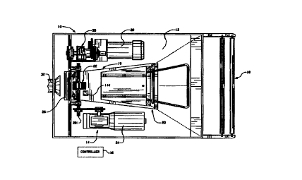
Figure 18 illustrates one embodiment of the present invention, that is, a
conversion machine 530 which includes a shredding device 532. Although various
shredding devices 532 are well known in the prior art and each are
contemplated by
the present invention, the shredding device 532 receives sheet material 534
and
feeds the sheet material 534 into a plurality of parallel cutting blades 536
and 538
which rotate to longitudinally cut the sheet material 534 into a plurality of
strips 520
(Figure 15). A conveyor belt 540 may be used to support and urge the sheet
material 534 into the cutting blades 536 and 538. The conveyor belt 540 may be
free rolling, but preferably is powered by a motor or belt assembly as will be
discussed in greater detail infra with respect to Figure 20. The cutting
blades 536
and 538 may be smooth or serrated cutting blades to facilitate the
longitudinal
cutting of the sheet material 534.
When passed between the cutting blades 536 and 538, the sheet material
534 is cut into the elongated strips 520 (Figure 15) which are then directed
toward,
and expelled outwardly from, an exit opening 542 of the shredding device 532.
The
elongated strips 520 are generally expelled through the exit opening 542 at a
very
rapid rate, for example, a rate of about 125-450 feet per minute.
The conversion machine 530 may include a durable and inexpensive
discharge chute attachment 543 which is either local to or in physical
attachment
-32-
CA 02305788 2000-03-31
WO 99/17923 PCT/US98/20640
with the shredding device 532. As the sheet material 534 is converted info the
elongated strips 520 as it exits the parallel cutting blades 536 and 538, the
elongated strips 520 (Figure 15) are initially impacted or impelled against a
barrier
560. The barrier 560 causes the shredded strips 520 (Figure 15) to assume a
partially jammed state within a compression chamber or confined area 562
located
between the barrier 560 and the cutting blades 536 and 538.
Continued shredding of additional sheet material 534 by the shredding device
532 forces additional elongated strips 520 (Figure 15) into the confined area
562,
forming a dam of temporarily jammed strips 520 (Figure 15). Once a dam of
shredded strips 520 is formed, the front of the dam, which is located most
closely to
the cutting blades 536 and 538, serve as an additional barrier mechanism. As
additional amounts of the sheet material 534 are fed or pulled into the
shredding
device 532, the expelling force exerted by the cutting blades 536 and 538
forces the
strips 520 (Figure 15) into the confined area 562. As the strips 520 (Figure
15) are
forced against the barrier 560, the strips 520 (Figure 15) are confined within
the
confined area 562 and are forced to fold against themselves in a relatively
controlled
manner. Such folding and further insertion of strips 520 (Figure 15) into the
confined
area 562, causes the folded strips to become compacted against themselves in
relatively uniformly generated folds, thereby resulting in the accordion-
shaped mass
of crimped strips 522 as illustrated in Figure 16.
The function of the discharge chute attachment 543 is to serve as a pressure
sensitive barrier 560 for temporarily damming a passage of the strips 520
(Figure
15) which are expelled from the shredding device 532. Consequently, the
conversion machine 530 has a means for urging the barrier 560 toward a closed
position. Preferably, the barrier 560 is a compression door or gate 570 having
a
closed position located within a generally vertical plane, and an open
position,
located within a generally horizontal plane. Figure 18 illustrates the gate
570 in a
-33-
CA 02305788 2000-03-31
WO 99/17923 PCT/US98/20640
closed position, while Figure 19 illustrates the gate 570 in an open position
with the
crimped strips 522 traveling through a guide portion 604.
Initially the gate 570 is urged toward its closed position by an urging means
572. The urging means 572 may include a spring, a weight, or a pneumatically
or
hydraulically controlled piston 574 which is connected to the gate 570 by a
linkage
assembly 576. The force exerted by the urging means 572 upon the gate 570 may
be controlled by either the type of the characteristics of the spring used, or
by a
valve mechanism attached to the piston 574, depending upon the urging means
utilized. If, for example, a piston assembly is utilized, a fluid or air
pressure reservoir
580 may be provided and appropriately connected to the piston 574 via a hose
assembly 582, as illustrated in Figure 18. Electronic pressure sensors may
also be
used to determine the amount of pressure which is being exerted upon the gate
570
and to activate andlor release the urging means 572 when needed.
In the preferred embodiment, the confined area 562 is defined by the gate
570, its sidewalls {not shown), the guide portion 604 and by the cutting
blades 536
and 538. Once a dam, however, of partially jammed crimped strips 522 are
within
the confined area 562, the frictional resistance between the crimped strips
522 and
the interior surfaces of the guide portion 604 provides sufficient retaining
force to
eliminate the need for the gate 570. At this point the gate 570 may be
automatically
or incrementally raised to its open position as illustrated in Figure 19. In
this manner
the remaining dam of the crimped strips 522 serve the same function as the
gate
570 by providing a barrier by which the strips fold against themselves in a
relatively
controlled manner thereby creating the crimped strips 522. In an alternative
embodiment, a barrier-less paper restriction mechanism may be employed such
as,
for example, a narrowing passageway in which the strips 520 experience
increased
restriction as it travels along the passageway. Consequently, the folded,
crimped
strips 522 may be generated without use of the gate 570 or other mechanism as
the
barrier 560.
-34-
CA 02305788 2000-03-31
WO 99/17923 PCT1US98I20640
The length of the crimped strips 522 may also be adjusted. A cutting,
chopping, or shearing device 620 may be engaged at preselected intervals to
cut the
compressed strips 522 into the strip segments 523 as illustrated in Figure 17.
The
shearing device 620 may be a cutting blade 622 to cut the compressed crimped
strips. The length of the crimped strips 522 may be controlled by regulating
the rate
of passage of the strips 522 through the conversion machine 530 andlor by
regulating the rate or time interval between which the blade 622 cuts the
strips 522.
Therefore the conversion machine 530 may produce variable lengths of crimped
strips 522. After the crimped strips 522 have been formed they exit the
confined
area 562 and guide portion 604, and are deposited in a receiving bin 616 via a
chute
or ramp 618, as illustrated in Figure 19.
Figures 18 and 19 illustrate an embodiment in which the sheet material 534 is
advanced through the shredding device 532 and the length of the various
crimped
strips 522 is then determined by the shearing device 620. If, however, it is
desired
to provide pre-cut sheets of the sheet material 534 rather than transversely
cutting
the packaging material after it is formed, a feeder section 702 having a
transverse
cutting component 722 may be provided upstream from the shredding device 532
as
illustrated in Figure 20.
The feeder section 702 of Figure 20 contains a transverse cutting component
722 which includes four rotating cutting blades 724 which are mounted for
rotation
on a shaft 725. A cylinder roller 726 is in alignment with the shaft 725 and
preferably includes elastomeric material sections 728 for specific alignment
in
cooperation with the blades 724. Each of the blades 724 preferably includes a
generally serrated edge but also includes several gaps along its transverse
length in
order to provide only a partial cut of the sheet material 534 as it transfers
thereunder
in direction "A". With the sheet material 534 being transversely cut, it is
advanced to
a second pair of drive rollers 730 and 731 for further direction to the
shredding
device 532 to maintain the sheet material 534 in a position for advancement to
the
-35-
CA 02305788 2000-03-31
WO 99/17923 PCTIUS98/20640
cutting component 722. A first biased roller means 721 is biased toward and in
alignment with the first drive roller 720, wherein a second biased roller
means 731 is
biased toward and in alignment with the second drive roller 730. In such a
manner,
the sheet material 534 is advanced to the shredding device 532 with the sheet
material 534 cut in predetemlined lengths.
The first pair of drive rollers 720 and 721, the backing cylinder 726 and the
second pair of drive rollers 730 and 731 all rotate at approximately the same
circumferential speed. Each of the components in the feeder section 702 are
preferably greater than 15" wide in order to provide the sheet material 534 to
the
shredding device 532, thereby making the conversion machine 530 capable of
accommodating a sheet material 534 that is 15" wide. The first pair of drive
rollers
720 and 721 are preferably knurled or roughed to provide sufficient friction
for
advancing the sheet material 534 therethrough while the second pair of drive
rollers
730 and 731 preferably have a lower coefficient of friction than the first
pair of driver
rollers 720 and 721. Additionally, the second pair of drive rollers 730 and
731 have
a slightly larger diameter or rotate faster which yields a faster
circumferential speed
than the first pair of drive rollers 720 and 721 in order to the keep the
material 534
tight for proper partial cutting by the transverse cutting component 722.
Because of
the lower friction surface of the rollers 730 and 731, the additional tension
created by
the slightly faster circumferential speed of the second pair of drive rollers
is not
sufficient to tear or separate the resulting sheets 738 of the sheet material
534
simply by the action of the drive rollers 720 and 730. The separated sheet
material
534 is then fed into the shredding device 532 for shredding and formation of
the
crimped strips 522 as discussed in conjunction with Figures 18 and 19.
Although
Figures 18-20 illustrate the conversion machine 530 as separate components,
the
feed assembly, shredding devise, and restriction mechanism may be integrated
into
a single unit as illustrated in Figure 21. The operation of the integrated
conversion
-3fi-
CA 02305788 2000-03-31
WO 99117923 PCTIUS98/20640
machine of Figure 21 operates in substantially the same manner as the machine
of
Figures 18-20, consequently a detailed description of Figure 21 is omitted.
Referring to Figure 22, the conversion machine 530 of Figures 18-21 further
includes a monitoring system 650 including a controller 652 for monitoring the
operation and status of the conversion machine 530 through a plurality of
sensors
654a-654i and a display 656 for providing a visual indicia of machine
operation to a
user andlor a service technician. The monitoring system 650 is operable to
monitor
and display the machine operation in real time or alternatively may take
sample data
at prescribed time intervals and save the data in an internal or external
memory for
subsequent analysis purposes. In yet another alternative embodiment, the
monitoring system 650 may monitor machine operation in real time (or at
sampled
intervals) and communicate the data to a remote processor via a data
transmission
line or communications link to provide for monitoring and diagnostic
evaluation of
multiple conversion machines at various site locations as will be discussed in
greater
detail infra in conjunction with Figure 23.
The plurality of sensors 654a-654i monitor various, diverse operational
indicia
of the conversion machine 530. Each of the sensors 654a-6541 monitor a
particular
operating characteristic or machine parameter and report the characteristic or
parameter to the controller 652 via a wire or cable connection. Alternatively,
however, each sensor 654a-654i may use wireless technology such as radio-
frequency (RF) communication or infrared (IR) linking or other communication
methodologies such as, for example, use of fiber-optic cable or coaxial cable
to
communicate its data to the controller 652. Various types of sensors may be
utilized. For example, a bar code reader 654a may be positioned upstream from
the shredding device 532 near the feeder assembly 702 of Figure 20 to read any
bar
code data that may exist on a bar code label on the roll of sheet material
534. Such
data may include an inventory control number, color data and perhaps even
control
data to be utilized for the particular roll of sheet material 534. In
addition, such data
-3?-
CA 02305788 2000-03-31
WO 99/17923 PCTNS98I20640
may further include the paper characteristics for use in machine control
operations
like feed rate, moisture or chemical application or gate pressure as well as
other
types of control operations. Consequently, inventory control can be
effectuated by
identifying which colors and particular rolls of sheet material 534 are being
utilized.
Re-stocking inventory in response in such data may therefore be easily and
efficiently accomplished.
Other sensors may also be employed with the conversion machine 530. A
color sensor 654b may alternatively be used instead of, or in addition to; the
bar
code reader 654a. The color sensor 654b, which is commonly known in the art,
is
preferably located upstream of the shredding device 532 near the feeder
assembly
702 of Figure 20 and senses the color of the sheet material 534 to ensure that
the
desired color of sheet material 534 is, in fact, being utilized to foml the
crimped
strips 522.
A paper quantify sensor 654c is also preferably located upstream of the
shredding device 532 to monitor the accumulated amount of paper (sheet
material
534} which has been converted by the conversion machine 530. The paper
quantity
sensor 654c may be, for example, a feeder monitor which counts the number of
rotations of the drive roller 720 which the controller then preferably
converts the
rotation count data into a paper quantity. Alternatively, if the conversion
machine
530 operates at only a single speed, the paper quantity sensor 654c may
constitute
a timer which monitors the on-time of the conversion machine 530 and the
controller
estimates the amount of paper used based upon the machine run time. Any
sensing
methodology by which the amount of sheet material 534 used by the conversion
machine 530 is monitored is contemplated by the present. invention. The
information
regarding the amount of paper used may then be utilized to easily and
efficiently
calculate use charges, etc. if the conversion machine 530 is being teased or
charged
based on the paper amount used. Further, the information may also be used to
schedule preventative maintenance for the conversion machine 530.
-38-
CA 02305788 2000-03-31
WO 99/17923 PCT/US98/20640
Shredding device sensors 654d and 654e may also be employed within the
conversion machine 530, as illustrated in Figures 18 and 19. The shredding
motor
sensor 654d monitors one or more motors which drives the transverse cutting
component 722 and the cutting blades 536 and 538 to evaluate the status of the
motors (not shown) and thus the status of the transverse cutting component 722
and
the cutting blades 536 and 538. For example, the shredding motor sensor 654d
may be one or more current sensors which monitor the load current of the
shredding
motors of the cutting blades 536 and 538. Any load current that rises above a
predetermined current threshold (IT,,) may be indicative of a dulling or
misalignment
of the cutting blade 536 and 538, since an excessive amount of power is being
expended by the motors.
A temperature sensor 654e also may be utilized instead of, or addition to, the
shredding motor sensor 654d to monitor various aspects of the shredding device
532. The temperature sensor 654e may be a single sensor (such as, for example,
a
thermocouple and an AID converter) or may include multiple sensors
strategically
located about the shredding device 532 (or even about the entire conversion
machine 530). Thermal data may then be utilized by the controller 652 to
monitor
motor degradation (of either the shredding motors or feed motors), cutting
blade
dulling or misalignment, or variation in speed, etc. Consequently, the status
and
operational characteristics of the shredding device 532 can be easily and
efficiently
monitored by a user andlor service technician, allowing for any potential
problems to
be detected before a machine failure occurs. Although a shredding motor sensor
654d and temperature sensor 654e are utilized to monitor the shredding device
532,
other type sensing mechanisms may also be utilized and are contemplated by the
present invention.
A vibration sensor 654f is preferably utilized to monitor the vibrational
characteristics or modes of the conversion machine 530. The vibration sensor
654f
monitors the shredding device 532 to insure that vibrations due to machine
-39-
CA 02305788 2000-03-31
WO 99/17923 PCT/US98I20640
operation do not exceed a predetermined vibration threshold or other criteria.
As is
well known by those skilled in the art, the vibration characteristics of
various
components within an operational system may provide functional or diagnostic
information to a technician. For example, excessive vibration of the shredding
device 532 may be indicative of a jam in the shredding device 532 or an
operational
problem with the cutting blades 536 and 538. Furthermore, excessive vibrations
may also be indicative of an operational problem with the barrier 560 which
forms
the crimped strips 522. The vibration sensor 654f may be, for example, one or
more
accelerometers and may be positioned strategically about the shredding device
532
or at other portions of the conversion machine 530 to monitor the operation of
the
conversion machine 530.
A pressure sensor 6548 may also be utilized within the conversion machine
530. In a preferred embodiment, the pressure sensor 6548 monitors the status
of
the gate 570 which constitutes the barrier 560 by which the crimped strips 522
are
initially fom~ed. Once a particular pressure threshold is reached, the gate
570 is
forced info a partial or complete open position to thereby allow the crimped
strips
522 to travel toward the receiving bin 616. Failure of the gate 570 to open at
the
prescribed pressure level may result in the crimped strips 522 within the
confined
areas 562 causing a jam at the shredding device 532. Consequently, the
pressure
sensor 6548 may monitor the force being exerted against the gate 570. If the
pressure needed to raise the gate 570 exceeds a predetermined threshold, the
pressure sensor 654g may communicate such a status to the controller 652. The
pressure sensor 654g may measure the force exerted against the gate 570 by,
for
example, measuring the force being exerted at the hinge of the gate 570, such
a
measurement being, for example, a torque measurement. Other methods by which
the pressure sensor 6548 may monitor the status of the gate or the pressure at
the
cutting blades 536 and 538 are also contemplated by the present invention. For
-40-
CA 02305788 2000-03-31
WO 99/17923 PCTItTS98/20640
example, a position sensor in conjunction with a potentiometer or a linear
variable
differential transducer (LVDT) may be utilized.
Another sensor that may be employed in the monitoring system 650 is a
shear force sensor 654h which senses or measures the shear force being exerted
by the transverse cutting blade 622 before the crimped strips 522 exit the
conversion
machine 530 and enter the receiving bin 616. As stated earlier, the transverse
cutting blade 622 is operable to cut the crimped strips 522 into selectable
lengths,
thereby resulting in sheared fragments or segments as illustrated in Figure
17. It is
desirable, therefore, for the transverse cutting blade 622 to cut the crimped
strips
522 with a minimal amount of force so as to ensure cutting of the front
portion 524
and back portion 526 of the crimped strips 522 to thereby form the segments
523.
Consequently, the shear force sensor 654h is operable to monitor the shear
force
being exerted by the transverse cutting blade 622 against the crimped strips
522. if
the shear force exerted by the transverse cutting blade 522 does not meet or
exceed
a predetermined force threshold, the shear force sensor 654h provides an
indication
of such a operation characteristic to the controller 652. Alternatively, the
sensor
654h may additionally communicate the shear force data to the controller 652
for
continuous monitoring.
Lastly, the monitoring system 650 may include a container sensor 654i. The
container sensor 654i may entail a bar code reader to thereby read a bar code
label
on the container 616. The bar code label may contain information regarding the
customer identity and/or the container volume. Consequently, the container
sensor
654i can relay such information to the controller 652 for use in recording the
usage
of various customers for marketing and/or control purposes. in addition, the
container volume data may be utilized to evaluate whether sufficient amounts
of the
crimped strips 522 are being used to fill the container bin 616 having a known
volume for quality control purposes. The container sensor 654i may also
include a
weight sensor to correlate the volume of the strips 522 placed in the bin 616
with
-41-
CA 02305788 2000-03-31
WO 99117923 PCT/US98/20640
other data collected from other sensors 654a-654h to ensure that the sensors
are
accurately measuring their respective operation characteristics or parameters.
Preferably, the controller 652 illustrated in Figures 18, 19, 22 and 23 is a
universal type programmable controller such as a programmable logic controller
(PLC), the configuration and programmability of which is well known to those
skilled
in the art. The universal type controller is preferred because it allows for a
single
type of controller configuration to be adaptable to various machine
variations.
Further, a universal controller allows for reduced set-up time, reduces
assembly
cost, and makes maintenance easier and less expensive. Lastly, universal
controllers are beneficial since training of the repair technician is
minimized and
since an inventory of universal controllers may be easily maintained. Although
a
universal controller is preferred, any custom-type controller may also be
utilized and
is contemplated as falling within the scope of the present invention. For
example,
any 8-bit, 16-bit or 32-bit custom, programmable I/O controller may be
utilized on
conjunction with the present invention.
An exemplary universal controller 652 is illustrated in Figure 22 and includes
a plurality of input ports 658a-658i devoted to receiving data from the
various
sensors 654a-654i. Preferably, the data received from each of the sensors 654a-
6541 is digital, single or mufti-bit digital data. Alternatively, however, the
controller
652 may incorporate an AID converter internally or external to the input ports
658a-
6581 to convert received analog signais into single or mufti-bit digital data.
In
addition, white the controller 652 is illustrated as a single, integrated
device, it is
noted that the controller 652 may be embodied as a plurality of controllers
that may
each be adapted for a particular function.
The controller 652 also includes a plurality of output ports 659a-659j
(wherein
j=1, 2. . . n) to provide control functions for the conversion machine 530.
For
example, the controller 652, via the output ports 659a-659j, is operable to
control the
main power, interlocks, operator panel switches and indicators, etc.
Consequently,
-42-
CA 02305788 2000-03-31
WO 99/17923 PCTNS98/20640
the controller 652 is operable to restrict the order of start up (by, for
example,
ensuring that the shredding device is running before the sheet rollers are
activated).
Since the controller 652 provides machine control functionality, the
controller 652
has a substantial amount of monitoring-type information without data ftom the
sensors 654a-6541. For example, the controller 652 has machine status
information
that may be evaluated for diagnostic purposes such as the onloff~dle status of
the
sheet motors and shredder motors, the accumulated run time of each component,
the electric safety interlocks on the operator access panels and the status of
safety
circuits such as, for example, the emergency stop circuit.
The controller 652 provides such control functions via its internal
programming. For example, since many of the control functions are onloff type
control functions, a 1-bit digital signal may comprise the control output
signal. For
variable type output control functionality, one or more mufti-bit control
signals may
be utilized (for example, to provide variable feed roller circumferential
control speed)
as will be appreciated by those skilled in the art.
The universal controller 652 receives the data from the sensors 654a-6541 at
the sensor input ports 658a-658i and stores, processes andlor displays the
data and
its internal control data on the display 656 which is preferably local to the
monitored
conversion machine 530. The controller 652, in response to the data at the
input
ports 658a-658i and its internal programming, generates a display output via a
display driver (not shown) to provide a visuai indicia of the machine status
on the
display 656. Alternatively, or in addition to the display, the controller 652
stores the
input data in an internal memory 660 andlor in an external memory 662. For
example, if the bar code reader 654a reads a bar code on a roll of sheet
material
534 and determines that a roll #10 of gray paper is being used, the controller
652
receives that data as a mini-bit piece of digital data, wherein, for example,
the first
three bifs are a color code and the next three bits constitute the particular
roll
number for that particular color. The controller 652 receives the mufti-bit
data,'
-43-
CA 02305788 2000-03-31
WO 99/17923 PCT/US98/20640
determines the color and roll number (via its internal programming, as is well
known
by those skilled in the art) and displays the data on the display 656 andlor
stores the
data in the memory 660 or 662 for later inventory analysis.
The paper quantity sensor 654c monitors the total amount of paper used by
the machine 530 or alternatively the amount of paper used on the present roll
of
sheet material 534 or both. Alternatively, the sensor 654c may monitor both
pieces
of data or separate sensors may be utilized for such a function. Preferably,
the
sensor 654c monitors the number of rotations of a feed roller and calculates
the
amount of paper by multiplying the rotation count by the known circumference
of the
drive roller. This data is then fed to the controller 652 (or alternatively
merely the
rotation count is sent to the controller 652 and the controller makes the
calculation
via its internal programming) and the amount of paper used is then displayed
on the
display 656 and/or downloaded into the memory 660 or 662, preferably at
predetermined time intervals. These time intervals may be, for example, every
five
minutes, every thirty minutes, each hour, or each day. The controller 652 may
also
provide a sheet material roll status indication to the user via the display
656 by
generating a warning indication or low paper indication on the display 656
when the
controller 652 determines that the amount of the sheet material 534 on the
roll is
almost finished.
Various other diagnostic functions are performed by the controller 652 in
conjunction with the sensors 654a-6541. In each of these monitoring functions,
the
sensors 654a-654i either convert the sensed condition into digital data
internally or
send the raw data to the controller 652 for subsequent processing. Preferably,
each
sensor 654a-654i converts its data to digital data to prevent errors due to
line loss
(via, for example, analog-to-digital converters), and the controller 652
performs any
subsequent processing to minimize the complexity and cost of each sensor 654a-
654i. Alternatively, however, the controller 652 may include AID conversion
capability as discussed earlier to further simplify each of the sensors 654a-
654i.
-44-
CA 02305788 2000-03-31
WO 99/17923 PCT/US98I20640
With several of the monitoring functions such as those provided by, for
example, the vibration sensor 654f and shear force sensor 654h, a warning is
preferably provided to the user visually via the display and/or audibly via an
alarm
when the monitored characteristic{s) exceeds or falls below a predetermined
parameter threshold. For example, the vibration sensor 654f senses the
vibration
modes of the conversion machine 530 at one or more locations. If the
conversion
machine 530 exceeds a predetermined vibration level at one or more locations,
the
controller 652 records the vibration level data in its memory 660 {or the
external
memory 662) and also compares the vibration data to a predetermined programmed
threshold. If the vibration data exceeds the threshold, the controller 652
generates
an error or warning signal to the user so that maintenance of the machine 530
may
be performed before a machine failure occurs. Preferably, the controller 652
generates a visual warning via the display 656 coupled with an audible warning
to
focus the user's attention on the system condition.
The controller 652 preferably provides such functionality in the following
manner. The controller 652.receives the vibration data (or, alternatively,
shear force
data, thermal data, etc.) and compares it to the predetermined threshold.
Preferably, the threshold is simply subtracted from the vibration data and if
the result
is positive, a warning is generated (indicating the vibration data exceeds the
threshold). Alternatively, the vibration data can be converted to a
corresponding
voltage via a look-up table and compared to a voltage corresponding to the
threshold via a comparator circuit as is well known by those skilled in the
art. The
controller 652 preferably maintains its status if no warning is needed and
may, if
desired, display the present vibration data on the display 656. Alternatively,
the
vibration data may be stored in the memory 660 and displayed on the display
656
only when prompted by the user via an ll0 peripheral (such as a keypad 664).
In the prefer-ed embodiment of the present invention, the monitoring system
650 of the conversion machine 530 simply displays the status of the various
system
-45-
CA 02305788 2000-03-31
WO 99117923 PCT/US98/20640
characteristics as measured by the sensors 654a-654i. Alternatively, however,
the
controller 652 may also control the operation of the conversion machine 530
via a
machine disable output 666 coupled to a machine power control 668. If, for
example, the controller 652 received data from one of the sensors 654a-654i
that
the controller 652 determined (via its internal programming) constitutes a
dangerous
condition that could cause machine damage, etc., the controller 652 may
trigger the
machine disable output 666 to turn off the conversion machine 530 via the
machine
power control 668 and relay the condition to the user via the display 656. In
this
manner the monitoring system 650 collectively provides machine conversion
control
to prevent machine damage or failure.
In the previous embodiment of the present invention, the monitoring system
650 monitored the status and operating' characteristics of the conversion
machine
530 and stored and displayed the results locally in the memory 660 or 662 and
the
display 656. According to another embodiment of the present invention, a
monitoring system 716 is operable to monitor the status and operating
characteristics of the conversion machine 530 of Figures 18-22 and transmit
the
data to another location for remote monitoring and diagnostic analysis, as
illustrated
in Figure 23.
With reference to Figure 23, there is shown a monitoring system 816 having a
controller 817 local to one or more conversion machines 530 for communication
with
a remote processor 818, such as a remote terminal or personal computer,
through a
pair of modems 820, 822, respectively, over a transmission line or
communication
link 824. (The remote processor 818 and corresponding modem 822 are designated
as separate from the controller 817 by the dashed box 826 indicating a remote
location, such as a service center.) The controller 817 is generally
equivalent to the
controller 652 described above relative to Figures 18 through 22. As is
discussed
above, the controller 81? receives a number of inputs 827a-827i corresponding
to
events detected by the sensors 654a-654i shown in the Figures 18 though 22.
The
-46-
CA 02305788 2000-03-31
WO 99117923 PCT/US98I20640
characteristics and status sensed by the sensors 654a-654i include the type
and
quantity of paper being used, the container being filled, etc. and further
includes
detection of machine errors, such as jams in the feeder or cutting assemblies
702
and 532, excessive vibrational modes due to misalignments, etc., the shear
force
exerted by the cutting mechanism 622 and various other types of information.
In
addition, the controller 817 has one or more output ports 859a-859i to provide
machine control functionality.
The controller 817 may also be provided with a real-time clock 829 to report a
number of time events, for example, the total time the machine is on, the
total time
the machine is active as opposed to the time devoted to maintenance arid the
total
time the feed motor or cut motor is running. The real-time clock 829 can also
be
used to time and date stamp occurrences of faults or warning conditions
detected by
the controller 817. Although the clock 829 is only illustrated in conjunction
with
Figure 23, the clock 829 is also equally applicable to the monitoring system
650 of
Figure 22.
All information received by the controller 817 may be stored in an internal
memory 829 or an external, non-volatile memory 830 for later retrieval. When
desired, the information stored in the memory 829 or 830 may be accessed from
the
remote location 826 through communication between the remote processor 818 and
the controller 817 over the modems 820 and 822. The modems 820 and 822 may
be conventional, commercially available modems communicating over a telephone
link 824 through conventional communications protocols as would be appreciated
by
those skilled in the art.
The information stored in the memory 829 or 830 of the controller 817 may be
automatically downloaded to the remote processor 818 at pre-planned time
intervals, for example, at the end of a day, or the end of a week.
Alternatively, a
service person at the remote location 826 can instruct the controller 817
through the
connection with the remote processor 818 via the modems 820 and 822 to
download
-47-
CA 02305788 2000-03-31
WO 99/17923 PCT/US98/20640
the information stored in the memory 829 or 830 to the remote processor 818 as
desired. Further, the connection between the remote processor 818 and the
controller 817 allows a service person to view in real-time or near real-time
the
status of machine 530 corresponding to the sensors 654a-654i and other inputs
described above, while the machine 530 is running. This enables the service
person
to remotely diagnose errors in the conversion machine 530 since the service
person
is able to look at sensor information from the machine 530 as an error is
occurring in
real-time. The information downloaded to the remote processor 818 from the
memory 820 or 830 can also be used to schedule maintenance for the machine 530
and to perform billing functions in instances where a customer is charged for
use of
the machine 530 based on its operating time, on the amount of paper fed
through
the machine 530, or on the number of sheared strips 523 produced by the
machine
530. The information downloaded to the remote processor 818 can further be
used
to effectuate inventory control by identifying what types and quantities of
paper are
being used so that paper inventories can be automatically replenished in a
timely
manner.
In instances where a service person is at the site of the conversion machine
530, it is also possible to access the memory 820 or 830 through the same port
provided for communication with the remote processor 818. In such a case,
instead
of the modem 820 being connected to the controller 817, a personal computer or
other terminal may be connected to the controller 817 for access and
downloading
of the information stored in the memory 829 or 830. Alternatively, the service
person may view the operational status of the machine 530 via the display 656
and
the key pad 664.
The controller 817, which is resident in the conversion machine 530 or local
to
the conversion machine 530, and the remote processor 818 can also function as
a
real-time diagnostics system for the conversion machine 530 by utilizing the
modems 820 and 822 and the transmission fine 824 to provide real-time or near
-48-
CA 02305788 2000-03-31
WO 99!17923 PCTIUS98/20640
real-time communication between the controller 817 and the remote processor
818.
Near real-time communication allows an operator at a central location, such as
a
servicing or distribution location 826, to obtain operational information on
the
performance of one or more conversion machines 530 as the machines are
operating. The machine information may be used as a diagnostic measure to
detemline if the machine 530 is functioning properly or is in need of
preventive
maintenance. For example, if the remote processor 818 determines, based on
information received from the controller 817 in real-time, that a motor runs
excessively long or drawn excessive current, the remote processor 818 can
infer
that the motor is excessively worn and schedule a replacement before the motor
fails. The machine infom~ation may also be used to diagnose or correct machine
problems, as well as to determine that the machine 530 is being operated
correctly
by an operator.
Some types of information which the remote processor 818 can receive from
the machine controller 817 includes the status of any machine sensor 654a-
6541.
The controller 817 may also provide information to the remote processor 817
relating
to control commands or instructions produced by the controller 817, including
the
machine output disable port 660. The remote processor 818 can also access,
through the controller 817, any of the internal or external memory locations
829 or
830 to provide an in depth view of the functioning of the machine 530 and to
analyze
whether the controller 817 is receiving and processing data correctly.
Aside from requesting information from the controller 817, the remote
processor 818 can also provide input to the controller 817 to instruct the
controller
817 to execute a predetermined test (as dictated by the internal programming
of the
controller 817) or the remote processor 818 may change threshold values in the
remory 829 or 830 of the controller 817 to monitor the function of the
conversion
machine 530 in accordance with desired inputs. Further, the internal
programming
control routines may be modified from the remote site 826, thereby allowing
software
-49-
CA 02305788 2000-03-31
WO 99/i'f923 PCT/US98/20640
monitoring, control and diagnostic upgrades to be easily implemented globally
to
multiple machines 530 from one central location.
Consequently, a skilled servicing technician at a central location can follow
the operation of a remote conversion machine 530 in real-time or near real-
time as
the machine 530 is operating to allow the service technician to readily
ascertain the
functioning of the machine 530 and to correct errors. In addition, the
servicing
technician can recommend different operating guidelines to an operator or a
technician working with the machine 530 in diagnosing and correcting problems
in
the machine 530. Furthermore, the technician at the central location can
monitor the
inventories at the remote site to ensure that sufficient quantities of the
various colors
of paper are available before they are actually required.
Although the monitoring systems 650 and 816 of the present invention have
been disclosed in conjunction with the conversion machine 530 of Figures 18-
23, it
should be understood that the present invention is equally applicable to
various,
diverse types of packaging material conversion machine and packaging material
dispensing machines. For example, the monitoring systems 650 and 816 are
equally applicable to a packaging material conversion machine that produces
various types of dunnage such as cushion pads, styrofoam peanuts, plastic
wrapping materials, etc. In addition to being applicable to machines that
produce
such dunnage, the present invention is also contemplated as applying to
various
types of apparatus that dispense such dunnage info containers and/or apply
such
dunnage to various objects for packing.
Although the invention has been shown and described with respect to certain
preferred embodiments, it is obvious that equivalent alterations and
modifications
will occur to others skilled in the art upon the reading and understanding of
this
spec~cation and the annexed drawings. Iri particular regard to the various
functions
performed by the above described components (assemblies, devices, sensors,
circuits, etc), the terms (including a reference to a "means") used to
describe such
-50-
CA 02305788 2000-03-31
WO 99/17923 PCT/US98l20640
components are intended to correspond, unless otherwise indicated, to any
component which performs the specified function of the described component
(i.e.,
that is functionally equivalent), even though not structurally equivalent to
the
disclosed structure which performs the function in the herein illustrated
exemplary
embodiments of the invention. In addition, while a particular feature of the
invention
may have been disclosed with respect to only one of several embodiments, such
feature may be combined with one or more other features of the other
embodiments
as may be desired and advantageous for any given or particular application.
-51-