Note: Descriptions are shown in the official language in which they were submitted.
' CA 02305955 2000-04-19
Case 2503 Patent Application
REMOVABLE HOSE AND TOOL CADDY FOR A VACUUM CLEANER
BACKGROUND OF THE INVENTION
Technical Field
The invention relates to vacuum cleaners. Particularly, the
invention relates to vacuum cleaner hose and tool storage. Even more
particularly, the invention relates to a hose and tool caddy which may be
easily mounted on or removed from an upright vacuum cleaner.
Background Information
It is well known that vacuum cleaners typically fall into one of
several categories, including uprights, canisters, and sticks. Upright vacuum
cleaners are generally perceived as providing superior floor care. Canister
cleaners are generally perceived as providing a certain degree of flexibility
in
use, accommodating both floor care and above-the-floor cleaning. Stick
cleaners are generally perceived as providing for quick cleanup of floor
surfaces and the like, and are appreciated for their ease of storage and ready
availability.
To increase the popularity of upright cleaners and eliminate the
perception that upright cleaners could only be used for floor care, or were
difficult to change from floor care to above-the-floor cleaning, valve
arrangements, such as that shown in U.S. Patent No. 5,134,750 assigned to
a common assignee, were added to upright cleaners. These valve
arrangements allowed upright cleaners to be easily changed between the
floor care and above the floor cleaning modes. However, the above-the-floor
cleaning mode typically requires an accessory hose and accessory tools,
such as a crevice tool, dusting brush, furniture nozzle and extension wand.
The problem with including valve arrangements on upright cleaners
1
CA 02305955 2003-09-15
61935-153
then became storage of the hose and accessory tools.
Typically, the hose and tools were stored in a closet or
drawer and were not readily available when the vacuum
cleaner was in use. Thus, on-board hose and tool storage,
such as a tool caddy or a tool storage compartment, was
developed allowing hoses and accessory tools to be stored
directly on upright vacuum cleaners. Examples of on-board
hose and tool storage are shown in U.S. Patent
No. 5,137,156, U.S. Patent No. 5,233,722, U.S. Patent
No. 5,247,719, U.S. Patent No. 5,303,447 and U.S. Patent
No. 5,331,714, assigned to a common assignee.
Although it is convenient to have the hose and
accessory tools mounted directly on upright vacuum cleaners,
there may be instances when upright cleaners are only being
used in the floor care mode. In such a case, it may be
undesirable to include the extra weight of the hose,
accessory tools and tool caddy on the cleaner.
Therefore, the need exists for a hose and tool
caddy which may be mounted on an upright vacuum cleaner
allowing the hose and accessory tools to be easily accessed
for above-the-floor cleaning, or which may be easily removed
from the upright cleaner when the upright cleaner is only
being used for floor care.
SUMMARY OF SHE INVENTION
According to the present invention, there is
provided in combination, an upright vacuum cleaner and an
accessory caddy removably mounted to the upright vacuum
cleaner for receiving vacuum cleaner accessories, said
upright vacuum cleaner having a bag housing and an upper
handle portion, said bag housing being formed with a
vertically extending side wall and a top wall, said
2
CA 02305955 2003-09-15
61935-153
accessory caddy including: a base; a connector for
removably mounting said base on the side wall of the bag
housing; an accessory retainer formed on the base for
storing the vacuum cleaner accessories; and whereby the
accessory caddy and the vacuum cleaner accessories stored
thereon may be slidably removed from the upright vacuum
cleaner by merely applying a force to said base.
Also according to the present invention, there is
provided in combination, an upright vacuum cleaner having a
housing and a removable caddy which may be mounted on and
removed from the housing for storing vacuum cleaner
accessories on the upright vacuum cleaner, said removable
caddy including: a base which removably mounts to the
housing; a connector on the base for removably mounting the
base on the housing; an accessory retainer formed on the
base for storing the vacuum cleaner accessories; and whereby
the caddy and the vacuum cleaner accessories stored thereon
may be slidably removed from the upright vacuum cleaner by
merely applying a force to said base.
According to the present invention, there is
further provided in combination, an upright vacuum cleaner
having a housing assembly which includes a housing formed
with a dirt collecting receptacle and a handle extending
upwardly from the housing, and a caddy removably mounted on
the housing for storing vacuum cleaner accessories, said
caddy including: a base which removably mounts to the
housing; a connector on the base for removably mounting the
base on the housing; an accessory retainer formed on the base
for storing the vacuum cleaner accessories on the caddy; and
whereby the caddy and the vacuum cleaner accessories stored
thereon may be slidably removed from the upright vacuum
cleaner by merely applying a force to said base.
3
CA 02305955 2003-09-15
61935-153
According to the present invention, there is
further provided in combination, an upright cleaning
appliance having a housing assembly which includes a housing
for supporting a receptacle and a handle extending upwardly
from the housing, and a caddy removably mounted on the
housing for storing cleaning accessories, said caddy
including: a base which removably mounts to the housing; a
connector on the base for removably mounting the base on the
housing; an accessory retainer formed on the base for
storing the cleaning accessories on the caddy; and whereby
the caddy and the vacuum cleaning accessories stored thereon
may be removed from the upright cleaning appliance by merely
applying a force to said base.
According to the present invention, there is
further provided in combination, an upright vacuum cleaner
and an accessory caddy removably mounted to the upright
vacuum cleaner for receiving vacuum cleaner accessories,
said upright vacuum cleaner having a housing and an upper
handle portion, said housing being formed with a vertically
extending side wall and a top wall, said accessory caddy
including: a base having an inner surface, an outer
surface, a top, a front and a rear; a handle extending
upwardly from the top of the base; a connector for removably
mounting said base on the side wall of the housing; and an
accessory retainer formed on the base for storing the vacuum
cleaner accessories.
According to the present invention, there is
further provided in combination, an upright vacuum cleaner
having a housing and a removable caddy which may be mounted
on and removed from the housing for storing vacuum cleaner
accessories on the upright vacuum cleaner, said removable
caddy including: a base which removably mounts to the
3a
CA 02305955 2003-09-15
61935-153
housing; a connector on the base for removably mounting the
base on the housing; an accessory retainer formed on the
base for storing the vacuum cleaner accessories; and in
which the housing includes a track member.
According to the present invention, there is
further provided in combination, an upright vacuum cleaner
having a housing and a removable caddy which may be mounted
on and removed from the housing for storing vacuum cleaner
accessories on the upright vacuum cleaner, said removable
caddy including: a base which removably mounts to the
housing; a connector on the base for removably mounting the
base on the housing; an accessory retainer formed on the
base for storing the vacuum cleaner accessories; and a
handle extending from the base.
According to the present invention, there is
further provided in combination, an upright cleaning
appliance having a housing assembly which includes a housing
for supporting a receptacle and a handle extending upwardly
from the housing, and a caddy removably mounted on the
housing for storing cleaning accessories, said caddy
including: a base which removably mounts to the housing; a
connector on the base for removably mounting the base on the
housing; an accessory retainer formed on the base for
storing the cleaning accessories on the caddy; and in which
the housing includes a track member.
According to the present invention, there is
further provided in combination, an upright cleaning
appliance having a housing assembly which includes a housing
for supporting a receptacle and a handle extending upwardly
from the housing, and a caddy removably mounted on the
housing for storing cleaning accessories, said caddy
including: a base which removably mounts to the housing; a
3b
CA 02305955 2003-09-15
61935-153
connector on the base for removably mounting the base on the
housing; an accessory retainer formed on the base for
storing the cleaning accessories on the caddy; and a handle
extending from the base.
An aspect of the invention provides an upright
vacuum cleaner having a housing, and a removable caddy which
may be mounted on and removed from the upright vacuum
cleaner for storing vacuum cleaner accessories, said
removable caddy including a base which removably mounts to
the upright vacuum cleaner; a connector on the base for
removably mounting the base on the upright vacuum cleaner;
and an accessory retainer formed on the base for storing the
vacuum cleaner accessories.
Embodiments of the invention provide an improved
hose and tool caddy capable of storing a vacuum cleaner hose
and/or vacuum cleaner accessory tools.
Embodiments of the invention provide such a hose
and tool caddy which may be mounted on an upright vacuum
cleaner providing convenient access to the hose and
accessory tools for above-the-floor cleaning.
Embodiments of the invention provide such a hose
and tool caddy which may be easily removed from the upright
vacuum cleaner when the upright vacuum cleaner is being used
only for floor care.
Embodiments of the invention provide such a hose
and tool caddy which may be easily stored when the hose and
tool caddy is removed from the upright vacuum cleaner.
Embodiments of the invention provide such a hose
and tool caddy which reduces the weight of the upright
3c
CA 02305955 2003-09-15
61935-153
vacuum cleaner when the hose and tool caddy is removed
therefrom.
BRIEF DESCRIPTION OF DRAWINGS
The preferred embodiment of the invention,
illustrative of the best mode in which applicants have
contemplated applying the principles is set forth in the
following description and is shown in the drawings and is
particularly and distinctly pointed out and set forth in the
appended claims.
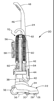
FIG. 1 is a right side elevational view showing an
upright vacuum cleaner and removable hose and tool caddy
attached thereto;
FIG. 2 is a perspective view of the hose and tool
caddy of FIG. l;
FIG. 3 is a rear view of the hose and tool caddy
of FIG. 2;
FIG. 4 is a right side elevational view of the
hose and tool caddy of FIG. 3;
FIG. 5 is a front elevational view of the hose and
tool caddy of FIG. 4;
FIG. 6 is a left side elevational view of the hose
and tool caddy of FIG. 5 showing a guide member exploded
therefrom;
3d
CA 02305955 2000-04-19
FIG. 7 is front elevational view of the guide member of FIG. 6;
FIG. 8 is a right side elevational view of the guide member of FIG.
7;
FIG. 9 is a sectional view taken along line 9-9, FIG. 8;
FLG. 10 is a fragmentary perspective view of the housing of the
upright vacuum cleaner of FIG. 1 showing a recessed area formed in the left
rear portion thereof;
FIG. 11 is a perspective view of a track member which is received
within the recessed area of the housing;
FIG. 12 is a ftagmentary perspective view similar to FIG. 10
showing the track member assembled within the recessed area; and
FIG. 13 is a fragmentary sectional view taken along line 13-13,
FIG. 12.
Similar numerals refer to similar parts throughout the drawings.
DESCRIPTION OF THE PREFERRED EMBODIMENT
An upright vacuum cleaner is shown in FIG.1 and is indicated
generally at 20. Upright vacuum cleaner 20 includes a foot 22 and an upper
housing assembly 24 pivotally connected to foot 22. Foot 22 is similar to
those known in the art and includes a nozzle opening 26 for receiving a
stream of dirt-laden air and an agitator 28 for agitating and loosening dust
and
debris from a floor surface when upright vacuum cleaner 20 is in the floorcare
mode. Foot 22 further includes a pair of front wheels 30 rotatably mounted
on a wheel carriage (not shown), and a pair of rear wheels 32. A height-
adjustment knob 34 is positioned on foot 22 for adjusting the height of the
nozzle opening 26 relative to the floor surface.
Foot 22 is formed with a curved bottom surface 36 which receives
a motor fan housing (not shown). The motor-fan housing houses a motor-fan
assembly (not shown) which creates the suction necessary to remove the
loosened dust and debris from the floor surface. The motor-fan assembly
attaches to the upper housing assembly 24 by a dirt duct 38. The upper
4
CA 02305955 2000-04-19
housing assembly 24 houses a vacuum cleaner filter bag (not shown) for
receiving and filtering the dirt-laden air stream which is created by the
motor-
fan assembly and which is conveyed to the filter bag through dirt duct 38.
Upper housing assembly 24 includes a rear housing 40 which
forms the filter cavity for receiving the filter bag, a door 42 which encloses
the
cavity and which is formed with a plurality of exhaust slots 44, and an upper
handle 46 which extends upwardly from rear housing 40 and which is formed
with a rearwardly angled hand grip 48. The upright vacuum cleaner 20 may
be used in either a floor care mode whereby the suction from the motor-fan
assembly is directed to nozzle opening 26, or an above-the-floor cleaning
mode whereby the suction is directed to an accessory tool opening (not
shown). The accessory tool opening receives a proximate end 50 of an
accessory hose 52. Hose 52 includes a distal end 54 which receives the
tubular end of one of a plurality of accessory tools for use in above-the-
floor
cleaning. The accessory tools are shown in FIG. 1 and include a dusting
brush 56, a furniture nozzle 58, an extension wand 60 and a crevice tool 62
stored within wand 60. Dusting brush 56 and furniture nozzle 58 include a
tapered tubular end for insertion within eitherdistal end 54 of hose 52 orwand
60.
In the illustrated preferred form of the present invention, the hose
52 and the accessory tools 56, 58, 60 and 62 are stored on a hose and tool
caddy 70. Hose and tool caddy 70 is shown in detail in FIGS. 2-6 and
generally includes a base 72 and a guide member 74 (Fig. 6) which
removably mounts hose and tool caddy 70 on the upright vacuum cleaner 20.
With the point of reference being behind vacuum cleaner 20, base
72 includes a right side or outer surface 76 (Figs. 2 and 4), a left side or
inner
surface 78 (Figs. 5 and 6), a front 80 (Fig. 5), a rear 82 (Fig. 3), an
inwardly
curved top 84 (Figs. 2-5) and an outwardly extending bottom shelf 86. Outer
surface 76 of base 72 is formed with a looped channel 88 (Figs. 2 and 4) for
receiving hose 52 in a looped configuration. Looped channel 88 is generally
U-shaped in cross-section and includes a vertical front section 90 which
5
CA 02305955 2000-04-19
extends adjacent to front 80 of base 72, a looped top section 92 which loops
around inwardly curved top 84 of base 72, and a vertical rear which extends
adjacent to rear 82 of base 72. A vertically extending channel 96 having a
generally U-shaped cross-section is formed between front and rear sections
90 and 94, respectively, of looped channel 88 for receiving the extension
wand 60 and crevice tool 62 combination. A pair of tabs 98 extend inwardly
from opposed sides of vertical channel for frictionally retaining the
wandlcrevice tool combination on base 72. Vertical channel 96 is formed with
an inwardly curved top recess 100 for receiving a users fingers during the
removal of the wandlcrevice tool combination from its engagement with tabs
98.
Bottom shelf 86 is generally L-shaped and extends outwardly from
the bottom of base 72 (Figs 2 and 4). Shelf 86 includes a raised rear section
102 and a lower.front section 104. Rear section 102 is formed with a top
opening 106 for receiving proximate end 50 of hose 52. Front section 104 is
formed with a pair of circular holes 108 and 110 for receiving the end of
extension wand 60 and distal end 54 of hose 52, respectively. Shelf 86
includes a front wall 112, a rear wall 114 and an outer sidewall 116 which is
formed with a rectangular opening 118.
In the shown preferred embodiment of the invention, top 84 of
base 72 curves inwardly (Figs. 3 and 5) to follow the curved contour of rear
housing 40 of upright vacuum cleaner 20. A generally triangular shaped side
wall 120 (Figs. 2 and 4) extends vertically upwardly from top 84 and tapers
into a generally C-shaped hook 122. Hook 122 may be used as a handle for
grasping and removing hose and tool caddy 70 from upright vacuum cleaner
20 and may be used to hang hose and tool caddy 70 on a closet bar, door
knob or the like when hose and tool caddy 70 is in the removed position.
Base 72 includes a front wall 130 (Fig. 5) formed on front 80
thereof, and a rear wall 132 (Fig. 3) formed on rear 82 thereof. Front wall
130
extends outwardly to form an outer wall to front 90 of curved channel 88, and
extends inwardly to form a lip 134 on inner surface 78 of base 72. Rear wall
6
CA 02305955 2000-04-19
122 extends inwardly from the edge of rear 94 of curved channel 88. Lip 134
and rear wall 132 curve inwardly along the edge of top 84 to form front and
rear walls of hook 122. A pair of spacers 136 (Figs. 5 and 6) are formed on
inner surface 78 of base 72 for maintaining a spaced relationship between
base 72 and the right side of rear housing 40. A pair of resilient C-clamps
140 and 142 (Figs. 2 and 3) are formed integrally with and extend rearwardly
from rear wall 132 for fractionally retaining dusting brush 56 and furniture
nozzle 58, respectively. Each clamp 140 and 142 includes a pair of opposed
outwardly 'extending nubs 144, and a pair of opposed ribs 146 which are
positioned at the outer ends of C-clamps 140 and 142. Nubs 144 and ribs
146 contact the tubular ends of the accessory tools forfrictionally retaining
the
tools within C-clamps 140 and 142, as shown in Fig. 1.
In the preferred embodiment of the present invention, base 72 of
hose and tool caddy 70 is retained on upright vacuum cleaner 20 by guide
member 74 (Figs 6-9) which is slidably received within a track member 150
(Figs. 11-13). Guide member 74 is attached to inner surface 78 of base 72
between rear wall 132 and a support wall 152 (Fig. 6) which extends inwardly
from inner surface 78. Guide member 74 is formed with a first wall 158 (Fig.
9) which sits between rear wall 132 and support wall 152 and abuts inner
surface 78, a second wall 160 which extends outwardly from first wall 158 and
which is juxtaposed with support wall 152, and a third wall 162 which extends
outwardly from second wall 160. First wall 158 and third wall 162 extend at
a 90 degree angle to and in opposite directions from second wall 160.
Second wall 160 tapers slightly at a bottom 163 (Fig. 8) thereof. A plurality
of triangular fillets 164 extend between first wall 158 and second wall 160 to
strengthen guide member 74, with the top fillet 164 forming a top wall 166 of
guide member 74. A plurality of smaller fillets (not shown) may extend
between second wall 160 and third wall 162 to further strengthen guide
member 174. A connecting wall 170 is formed integrally with the outer end
of third wall 162 and extends at approximately a 45 degree angle thereto.
Connecting wall 170 is formed with opposed outer free side edges 171 (Figs.
7
CA 02305955 2000-04-19
8 and 9).
A screw lug 172 (Fig. 8) extends upwardly from top wall 166 and
is formed with a circular hole 174. A circular boss 176 extends outwardly from
first wall 158 and is attached at the side thereof to second wall 160. Lug 172
and boss 176 align with a pair of bosses 178 and 180 (Fig. 6), respectively,
of inner surface 78 of base 72 and receive a fastener such as a screw or the
like for attaching guide member 74 to base 72. A pair of slotted openings 182
(Fig. 8) are formed in the comer between first wall 158 and second wall 160
of guide member 74 for receiving a pair of barbed tabs 184 which extend
outwardly from inner surface 78 (Fig. 6) of base 72. Barbed tabs 184 snap-fit
with a raised latching surface 186 which surrounds the portion of slotted
openings 182 formed in first wall 158. Barbed tabs 184 cooperate with the
fasteners of lug 172 and boss 176 to attach guide member 74 to base 72. A
camming ramp 190 (Fig. 8) is formed on third wall 162 adjacent to connecting
wall 170 for providing a snug fit between guide member 74 and track member
150, as described below in further detail.
In accordance with the preferred embodiment of the invention,
housing 40 is formed with a vertically extending elongated recess 200 (Fig.
10) in the right rear comer thereof. Recess 200 receives track member 150
as shown in FIG. 12 and as described below. Track member 150 is shown
in Fig. 11 and is an elongated one-piece member having a rear wall 204, a
right side wall 206, a left side wall 208, a top wall 210 and a bottom wall
212.
A slotted opening 214 is formed in rear wall 204 by a pair of spaced inwardly
extending edge walls 215. Slotted opening 214 includes an upper section
216 which has an open top 217 and which tapers inwardly towards a lower
section 218. Rear wall 204 is angled inwardly from left side wall 208 to right
side wall 206 allowing track member 150 to conform to the angled contour of
rear housing 40 (Fig. 12).
A countersunk screw boss 220 (Fig. 11 ) is formed on rear wall 204
adjacent to left side wall 208 and is formed with a circular hole 222. A
retaining flange 224 extends upwardly from top wall 210 of track member 150
8
CA 02305955 2000-04-19
and includes a barbed tab 226 extending inwardly therefrom. A fillet 227
extends between top wall 210 and retaining flange 224. A second barbed tab
228 extends outwardly from right side wall 206. A tab (not shown) extends
downwardly from bottom wall 212 to hold the bottom of track member 150
within recess 200, as described below.
Rear housing 40 is formed with an outwardly extending elongated
cam 240 (Fig. 10) positioned within recess 200. Cam 240 is generally
triangular in shape with the outer edge thereof forming a camming surface
242. A boss 244 is formed within recess 200 and is countersunk within rear
housing 40 for receiving boss 220 of track member 150. An indented area
246 is formed in rear housing 40 which is slightly deeper then recess 200. A
rectangular opening 248 is formed in rear housing 40 within indented area
246. A second rectangular opening 250 is formed in rear housing 40 adjacent
the right side wall of recess 200. A pair of posts 252 extend outwardly from
within recess 200 and are positioned on either side of second rectangular
opening 250. A slotted opening 254 is formed in rear housing at the bottom
of recess 200.
Track member 150 is assembled within recess 200 of rear housing
40 by inserting the bottom tab of track member 150 within bottom slotted
opening 254. Right wall 206 extends between the posts 252 and the right
sidewall of recess 200. Barbed tab 228 of track member 150 is received
within opening 250 and snap-fits therein. Retaining flange 224 is positioned
within indented area 246 and barbed tab 226 of retaining flange 224 snap-fits
within opening 248. A fastener, such a screw 256, is inserted within hole 222
of boss 220 and engages boss 244. of rear housing 40. With retaining flange
224 sitting within indented area 246, upper handle 46 of upright vacuum
cleaner 20 is assembled to rear housing 40 to trap retaining flange in
position.
Upper handle 46, barbed tabs 226 and 228, the bottom post and screw 256
all cooperate to retain track member 150 within recess 200. Track member
150 encloses recess 200 to form an inner chamber 260.
With track member 150 attached to rear housing 40 and guide
9
CA 02305955 2000-04-19
member 74 attached to base 72, hose and tool caddy 70 may be removably
mounted on upright vacuum cleaner 20. Tool caddy is grasped by top hook
122 and lifted above rear housing 40 until connecting wall 170 aligns
vertically
with top opening 217 of upper section 216 of slotted opening 214. Third wall
162 of guide member 74 slides within slotted opening 214 with outer edges
171 of connecting wall 170 being held against the inner surface of rear wall
204 within chamber 260. As connecting wall 170 is inserted within chamber
260, the connecting wall will cam against ramming surface 242 of cam 240.
As connecting wall 170 approaches the bottom of slotted opening 214,
ramming ramp 190 contacts the left edge wall 215. The ramming ramp
pushes guide member 74 and thus hose and tool caddy 70 outwardly. This
outward force causes connecting wall 170 to abut the inner surface of edge
wall 215 creating a snug fit between guide member 74 and track member 150.
Spacers 136 abut the right side wall of rear housing 40 to maintain an equally
spaced distance between hose and tool caddy 70 and rear housing 40, and
to prevent twisting of the tool caddy relative to the rear housing.
Hose and tool caddy 70 may be easily removed from upright
vacuum cleaner 20 by merely grasping hook 122 and applying an upward
vertical force thereto. Guide member 74 will slide within track member 150
until the guide member disengages the track member and clears top opening
217. Hose and tool caddy 70 may be hung on a closet bar, door knob or the
like for storage when the tool caddy is in the removed position.
It is understood that although in the preferred embodiment hose
and tool caddy 70 is shown attached to an upright having a bag and a hard
bag housing closed by a bag door, the vacuum cleaner 20 could be a bagless
cleaner or a soft bag cleaner without affecting the concept of the invention.
It is also understood that slotted opening 214 may be formed directly in rear
housing 40, and that guide member 74 may be molded integrally with base
72 without affecting the concept of the invention.
Accordingly, the improved removable hose and tool caddy for a
vacuum cleaner is simplified, provides an effective, inexpensive, and
efficient
CA 02305955 2000-04-19
device which achieves all of the enumerated objectives. While there has
been shown and described herein a preferred embodiment of the present
invention, it should be readily apparent to persons skilled in the art that
numerous modifications may be made therein without departing from the true
spirit and scope of the invention. Accordingly, it is intended by the appended
claims to cover all modifications which come within the spirit and scope of
the
invention.
11