Language selection

Search

Patent 2306197 Summary

Third-party information liability

Some of the information on this Web page has been provided by external sources. The Government of Canada is not responsible for the accuracy, reliability or currency of the information supplied by external sources. Users wishing to rely upon this information should consult directly with the source of the information. Content provided by external sources is not subject to official languages, privacy and accessibility requirements.

Claims and Abstract availability

Any discrepancies in the text and image of the Claims and Abstract are due to differing posting times. Text of the Claims and Abstract are posted:

  • At the time the application is open to public inspection;
  • At the time of issue of the patent (grant).
(12) Patent Application: (11) CA 2306197
(54) English Title: GATE CORNER BRACKET
(54) French Title: SUPPORT D'ANGLE DE BARRIERE
Status: Deemed Abandoned and Beyond the Period of Reinstatement - Pending Response to Notice of Disregarded Communication
Bibliographic Data
(51) International Patent Classification (IPC):
  • E06B 11/06 (2006.01)
  • E05D 05/06 (2006.01)
  • E06B 11/02 (2006.01)
  • F16B 01/00 (2006.01)
  • F16B 07/18 (2006.01)
  • F16B 15/00 (2006.01)
(72) Inventors :
  • MEYER, GEORGE (Canada)
(73) Owners :
  • ROYAL CAPITAL STAMPING AND TOOLING LTD.
(71) Applicants :
  • ROYAL CAPITAL STAMPING AND TOOLING LTD. (Canada)
(74) Agent: DENNISON ASSOCIATES
(74) Associate agent:
(45) Issued:
(22) Filed Date: 2000-04-19
(41) Open to Public Inspection: 2001-10-19
Examination requested: 2000-04-19
Availability of licence: N/A
Dedicated to the Public: N/A
(25) Language of filing: English

Patent Cooperation Treaty (PCT): No

(30) Application Priority Data: None

Abstracts

English Abstract


A gate-corner is made from a plurality of flat
metal legs. These legs include first and second legs which
form the outside corner of the gate corner and third and
fourth legs which form a T-member to the inside of the gate
corner. The third leg has welded centrally of and is at a
right angle to the fourth leg which in turn has one end
welded to the first leg with the first and fourth legs
being perpendicular to one another. The end welding of the
third and fourth legs allows them to be deflected in the
event that the gate corner is fitted with irregular shaped
pieces of lumber.


Claims

Note: Claims are shown in the official language in which they were submitted.

-6-
THE EMBODIMENTS OF THE INVENTION IN WHICH AN EXCLUSIVE
PROPERTY OR PRIVILEGE IS CLAIMED ARE DEFINED AS FOLLOWS:
1. A gate corner made from a plurality of flat metal
legs comprising first and second legs meeting end to end
with and being perpendicular with one another, a third leg
having one end welded centrally of and being at a right
angle to a fourth leg, the fourth leg being parallel to and
spaced from the second leg with one end of the fourth leg
being welded to the first leg.
2. A gate corner as claimed in Claim 1, wherein said
first and second legs are part of a single elongated piece
of flat bar material with a right angle bend where the
first and second legs meet end to end with one another.
3. A gate corner as claimed in Claim 1, wherein said
legs form a pair of U-shaped brackets perpendicular to one
another, each bracket having a single wall base and one leg
secured thereto by a weld attachment.
4. A gate corner member comprising first and second
legs forming an outside corner region of said member, said
first and second legs being formed from a single strip of
metal bar bent to an L-shape, and third and fourth legs
forming an interior part of said member, said third and
fourth legs being arranged in a T-shape having a stem which
is said third leg and a head which is said fourth leg, said
third leg having one end thereof welded to said fourth leg
and said fourth leg having one end thereof welded to said
first leg, all of said legs cooperating to provide two U-
shaped brackets at 90° to one another.

Description

Note: Descriptions are shown in the official language in which they were submitted.


CA 02306197 2000-04-19
S~-10493
- 1 -
TITLE: GATE CORNER BRACKET
FIELD OF THE INVENTION
The present invention relates to a metal gate
corner which is used with wooden boards and other gate
corners in forming an overall gate construction.
BACKGROUND OF THE INVENTION
A conventional metal gate corner which is used with
lumber pieces in forming an overall gate comprises two
lengths of flat metal bar which are bent into two U-shaped
brackets. The base of one of the brackets is then welded
to the leg of the other bracket.
The above construction is extremely rigid and has
essentially no flexibility to fit with anything other than
a completely rectangular board of a size to fit snugly
within either bracket. However, it is often the case that
the boards are odd sized and odd shaped making gate
construction using conventional corner brackets very
difficult.
SUMMARY OF THE PRESENT INVENTION
The present invention provides a metal gate corner
which is very adaptable for working with odd shaped pieces
of lumber in forming an overall gate construction.
More specifically, the gate corner of the present
invention comprises a plurality of flat metal legs
comprising first and second legs meeting end to end and
being perpendicular with one another. Typically, these
first and second legs are formed from a single strip of
flat metal bent at 90°.

CA 02306197 2000-04-19
S~-1043
- 2 -
The gate corner further comprises a third leg
having one end welded centrally of a fourth leg with the
third and fourth legs being at generally right angles to
one another. The fourth leg in turn, has one end thereof
welded to the first leg and lies essentially parallel to
the second leg of the gate corner.
The key to the present invention lies in the end
welding of the third and fourth legs in the gate corner
construction allowing these two legs to be deflected if
necessary to comply with odd shaped lumber pieces within
the gate.
BRIEF DESCRIPTION OF THE DRAWINGS
The above as well as other advantages and features
of the present invention will be described in greater
detail according to the preferred embodiments of the
present invention in which;
Figures 1 and 2 show respectively a pair of
brackets and the assembly of those brackets used in a prior
art gate corner construction;
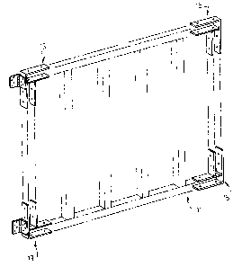
Figure 3 is a perspective view of an overall gate
assembled using gate corners according to a preferred
embodiment of the present invention;
Figure 4 is an enlarged side view of one of the
gate corners from the gate of Figure 3;
Figure 5 is an enlarged perspective view of the
gate corner of Figure 4;
Figures 6 and 7 are side views showing further
features of the gate corner of Figures 4 and 5 of the
drawings.
DETAILED DESCRIPTION ACCORDING TO THE PREFERRED EMBODIMENTS
OF THE PRESENT INVENTION IN WHICH:

CA 02306197 2000-04-19
SJ-10493
- 3 -
Figures 1 and 2 show a prior art gate corner
construction formed from a first metal bracket 3 and a
second metal bracket 5. Both of these metal brackets are
made from a single flat metal bar bent to the U-shapes
shown in Figure 1. The base 6 of the second bracket 5 is
then welded to the arm 4 of the first bracket 3 to form a
metal gate corner generally indicated at 7 in Figure 2.
Wooden boards are then slid into and secured within the
brackets. However, as is often the case, the boards are
not perfectly shaped to fit the interior confines of the
two brackets and the brackets themselves have essentially
no flexibility to conform to the boards.
In accordance with the present invention, a gate
corner generally indicated at 13, as best seen in Figure 5
of the drawings, does have such flexibility or
adjustability. The features of the gate corner providing
this flexibility will be described later in detail.
Figure 3 of the drawings shows an overall gate
construction using two of the gate corners 13 and two other
gate corners 15. The only difference between gate corners
13 and gate corners 15 is that corners 13 include hinges 35
not present on the corners 15. These hinges are used for a
swinging mount of the gate.
Gate corner 13 best seen in Figures 4 and 5 of the
drawings comprises a first flat metal bar with a right
angle bend 23 in the bar to form first and second legs 19
and 21 which are perpendicular to one another. These legs
form a rigid outside corner of the member.
Provided to the interior area of the gate corner is
a T-shaped member generally indicated at 25. This T-shaped
member comprises a third flat metal bar 27 forming the stem
of the T and a fourth flat metal bar 29 forming the head of

CA 02306197 2000-04-19
SJ-10493
- 4 -
the T. Bar 27 is welded at its interior end 31 centrally
of bar 29 such that these two bars are essentially
perpendicular to one another. Bar 29 is then welded at its
interior end 33 to bar 19.
Bar or leg 29 lies parallel to and spaced from leg
21 of the gate corner.
Figures 4 and 5 show that the overall construction
comprises a pair of U-shaped bracket members with each
bracket member having one leg attached to its respective
bracket by welding. These two brackets then receive boards
37 and 39 which are secured in place by screws fitting
through each of the brackets.
In a gate corner construction, it is important to
have the boards at 90° or at least essentially at 90° to
one another. Furthermore, it is important that they be
tightly secured within the two brackets. As earlier
described, this can often be difficult because of the
irregularities in the boards themselves. Examples of this
are shown are shown in Figures 6 and 7 of the drawings.
Figure 6 shows bracket 13 fitted with a board 41
which is supposed to completely fill the bracket between
legs 19 and 27 as is the case with board 39 in Figures 4
and 5 of the drawings. However, board 41 is undersized and
does not fill the bracket which would be a problem with the
relatively inflexible prior art gate corners.
In accordance with the present invention, board 41
is first screwed into the bracket by the screws penetrating
through leg 19. This leg, which determines the 90°
positioning of board 41 relative to board 37 is not
flexible and will hold its shape.

CA 02306197 2000-04-19
SJ-10493
- 5 -
The securing screws are then fitted through leg 27
into board 41 and as the screws thread into the board, they
pull leg 27 causing it to deflect towards the board at its
relatively flexible welded base 31. Therefore, the lower
end of leg 27 is drawn tightly up against leg 41 as shown
in Figure 6 of the drawings.
Figure 7 shows a situation in which the bracket
defined between legs 21 and 29 also receives an undersized
board 43. In this case, the screws are first passed
through leg 21 to assure that board 43 is at right angles
to board 41 and thereafter the screws are fitted through
leg 29 causing this leg to deflect at its welded base such
that the outer end of leg 29 is drawn tightly against and
secures board 43. The rigid leg 19 continues to hold board
41 with a further deflection of leg 27 occurring at its
relatively flexible base 31.
Although various preferred embodiments of the
present invention have been described in detail, it will be
appreciated by those skilled in the art that variations may
be made without departing from the spirit of the invention
or the scope of the appended claims.

Representative Drawing
A single figure which represents the drawing illustrating the invention.
Administrative Status

2024-08-01:As part of the Next Generation Patents (NGP) transition, the Canadian Patents Database (CPD) now contains a more detailed Event History, which replicates the Event Log of our new back-office solution.

Please note that "Inactive:" events refers to events no longer in use in our new back-office solution.

For a clearer understanding of the status of the application/patent presented on this page, the site Disclaimer , as well as the definitions for Patent , Event History , Maintenance Fee  and Payment History  should be consulted.

Event History

Description Date
Inactive: IPC from MCD 2006-03-12
Time Limit for Reversal Expired 2003-04-22
Application Not Reinstated by Deadline 2003-04-22
Deemed Abandoned - Failure to Respond to Maintenance Fee Notice 2002-04-19
Application Published (Open to Public Inspection) 2001-10-19
Inactive: Cover page published 2001-10-18
Letter Sent 2000-11-17
Inactive: Single transfer 2000-10-18
Inactive: Correspondence - Formalities 2000-10-18
Inactive: First IPC assigned 2000-07-06
Inactive: IPC assigned 2000-07-05
Inactive: Filing certificate - RFE (English) 2000-06-02
Application Received - Regular National 2000-05-29
Request for Examination Requirements Determined Compliant 2000-04-19
All Requirements for Examination Determined Compliant 2000-04-19

Abandonment History

Abandonment Date Reason Reinstatement Date
2002-04-19

Fee History

Fee Type Anniversary Year Due Date Paid Date
Application fee - standard 2000-04-19
Request for examination - standard 2000-04-19
Registration of a document 2000-10-18
Owners on Record

Note: Records showing the ownership history in alphabetical order.

Current Owners on Record
ROYAL CAPITAL STAMPING AND TOOLING LTD.
Past Owners on Record
GEORGE MEYER
Past Owners that do not appear in the "Owners on Record" listing will appear in other documentation within the application.
Documents

To view selected files, please enter reCAPTCHA code :


To view images, click a link in the Document Description column. To download the documents, select one or more checkboxes in the first column and then click the "Download Selected in PDF format (Zip Archive)" or the "Download Selected as Single PDF" button.

List of published and non-published patent-specific documents on the CPD .

If you have any difficulty accessing content, you can call the Client Service Centre at 1-866-997-1936 or send them an e-mail at CIPO Client Service Centre.


Document
Description 
Date
(yyyy-mm-dd) 
Number of pages   Size of Image (KB) 
Representative drawing 2001-09-18 1 9
Drawings 2000-10-17 4 77
Abstract 2000-04-18 1 18
Description 2000-04-18 5 188
Claims 2000-04-18 1 41
Drawings 2000-04-18 4 74
Filing Certificate (English) 2000-06-01 1 164
Courtesy - Certificate of registration (related document(s)) 2000-11-16 1 113
Reminder of maintenance fee due 2001-12-19 1 111
Courtesy - Abandonment Letter (Maintenance Fee) 2002-05-20 1 183
Correspondence 2000-06-01 1 16
Correspondence 2000-10-17 5 117