Language selection

Search

Patent 2306394 Summary

Third-party information liability

Some of the information on this Web page has been provided by external sources. The Government of Canada is not responsible for the accuracy, reliability or currency of the information supplied by external sources. Users wishing to rely upon this information should consult directly with the source of the information. Content provided by external sources is not subject to official languages, privacy and accessibility requirements.

Claims and Abstract availability

Any discrepancies in the text and image of the Claims and Abstract are due to differing posting times. Text of the Claims and Abstract are posted:

  • At the time the application is open to public inspection;
  • At the time of issue of the patent (grant).
(12) Patent: (11) CA 2306394
(54) English Title: BINDING MEANS
(54) French Title: MOYEN D'ATTACHE
Status: Expired
Bibliographic Data
(51) International Patent Classification (IPC):
  • B65B 57/02 (2006.01)
  • B65B 13/04 (2006.01)
  • B65B 13/18 (2006.01)
  • G01B 3/12 (2006.01)
  • G01B 21/06 (2006.01)
(72) Inventors :
  • EDSTROM, TOMAS (Sweden)
(73) Owners :
  • VALMET FIBERTECH AB (Sweden)
(71) Applicants :
  • VALMET FIBERTECH AB (Sweden)
(74) Agent: FETHERSTONHAUGH & CO.
(74) Associate agent:
(45) Issued: 2007-01-23
(86) PCT Filing Date: 1998-05-20
(87) Open to Public Inspection: 1998-12-30
Examination requested: 2003-03-17
Availability of licence: N/A
(25) Language of filing: English

Patent Cooperation Treaty (PCT): Yes
(86) PCT Filing Number: PCT/SE1998/000941
(87) International Publication Number: WO1998/058843
(85) National Entry: 2000-04-10

(30) Application Priority Data:
Application No. Country/Territory Date
9702406-1 Sweden 1997-06-23

Abstracts

English Abstract


A means for binding wire around an object. The means comprises a feeding unit
(2) with a feeding wheel (11) for feeding and
stretching the wire (3). The measuring of fed wire length normally takes place
in that the feeding wheel (11) rotates through a predetermined
number of revolutions. Sliding between the wire (3) and feeding wheel (11),
however, implies that the position of the wire cannot be
determined accurately. As a solution of this problem a separate measuring
means (5) is provided for continuously measuring the fed wire
length (3), where the measuring is carried out without the measuring means (5)
feeding the wire (3).


French Abstract

L'invention concerne un moyen permettant d'attacher un fil autour d'un objet. Ce moyen comprend une unité d'alimentation (2) dotée d'une roue (11) destinée à l'alimentation en fil (3) et à son étirement. Pour mesurer la longueur du fil avancé, on utilise normalement un nombre prédéterminé de tours de cette roue (11). Mais étant donné le glissement entre le fil (3) et la roue (11), la position du fil ne peut pas être déterminée avec précision. Selon l'invention, un moyen de mesure séparé (5) permet de mesurer en continu la longueur (3) du fil avancé, cette mesure étant réalisée sans que le moyen de mesure (5) n'assure l'alimentation du fil (3).

Claims

Note: Claims are shown in the official language in which they were submitted.


6


CLAIMS:


1. A method of binding an object, comprising:

a) feeding a predetermined amount of wire to the object,
the feeding being performed by a feed member;

b) measuring the amount of the wire as the wire is fed, the
measuring being performed in a measuring means separate and
downstream from the feed member, so that sliding of the wire
in said feed member does not affect measurement of the wire,
and said measuring comprising contacting a runner having a
contact surface provided with a substantially straight
profile with said wire, and maintaining said runner in
contact with said wire using a dolly roll arranged opposing
said runner;

c) stretching the wire and disposing the wire on the
object; and

d) forming a knot in the wire so as to bind the object.

2. The method of claim 1, wherein the step of feeding
the wire includes feeding the wire until an end of the wire
arrives in a predetermined position.

3. The method of claim 1 or 2, wherein the step of
feeding comprises turning the feed member in a first
direction.

4. The method of claim 3, wherein the step of
stretching includes retaining an end of the wire while
turning the feed member in a second, reverse direction.

5. The method of claim 4, wherein the step of
disposing the wire on the object comprises turning the feed
member in the reverse direction until the speed of the wire
is zero.


7


6. The method of claim 5, wherein the step of
disposing the wire includes measuring the amount of the wire
as the feed member is turned in the reverse direction.

7. The method of any one of claims 1 to 6, wherein
the wire is fed into a guide bar when the guide bar is in a
closed position.

8. The method of claim 7, wherein the step of
stretching comprises stretching the wire while the guide bar
is in an open position.

9. The method of any one of claims 1 to 8, further
comprising, after the step of forming a knot, cutting the
wire and drawing the wire back to a predetermined position.

10. Apparatus for binding wire around an object,
comprising:

a feed member for feeding said wire, said feed
member including a driven feed wheel for feeding and
stretching said wire, said feed wheel being arranged
upstream of the object to be bound, and

separate measuring means for continuously
measuring the length of said wire fed by said feeding
member, said measuring means being located downstream from
said feed member whereby said measuring means does not feed
said wire, sliding of the wire in said feed member does not
affect measurement of the wire, and said measuring means
comprising a runner including a contact surface having a
substantially straight profile for contacting said wire and
a dolly roll for assuring that said runner and said wire
remain in contact.

11. The apparatus of claim 10 including a rotation
meter coupled to said runner.


8


12. The apparatus of claim 10 or 11, further
comprising a guide extending around the object, the feed
member being located upstream of the guide.

13. The apparatus of claim 12, wherein the guide
comprises a bar having an open position and a closed
position.

14. The apparatus of claim 13, wherein the feed member
is arranged with the guide so that the bar is in the open
position during wire stretching and in the closed position
during wire feeding.

15. The apparatus of claim 13 or 14, wherein the bar
has grooves for said wire.

16. The apparatus of any one of claims 10 to 15,
wherein the feed wheel is rotatable in a first direction to
feed said wire and rotatable in a second direction to
stretch said wire.


Description

Note: Descriptions are shown in the official language in which they were submitted.


CA 02306394 2000-04-10
WO 98/58843 PCT/SE98/00941
Binding means
This invention relates to a means for binding wire around objects, for example
bales of
fiber material.
Pulp bales are bound around both individually and in the form of stacked units
comprising
a certain number of bales, usually six or eight bales. Such a unit load has a
weight of
between one and two tons. The strength of the wire binding tying together the
unit load,
therefore, is very important from a safety point of view, because several
persons may
stand near the load while it is being lifted by its wires. The equipment used
for tying the
knot in a bound wire loop and the knot itself, therefore, are subject of very
comprehensive
safety regulations and stringent safety controls.
The binding means comprises a unit for feeding the wire from a wire magazine
through
an openable wire guide bar around the object.
The feeding unit is used also for stretching the wire. The means comprises
further a
twining member, which includes a unit for locking the wire end, a unit for
tying a
wire knot, a cutting unit and a unit for projecting the knot.
The wire guide bar extends around the object to be bound and guides the wire
at its feed.
The wire is fed through the twining member around the object to be bound. When
the free
end of the wire arrives for the second time at the twining member, the wire is
stopped
and retained in the locking unit, whereafter the wire is stretched by
reversing the feeding
unit. The wire guide bar is thereby opened, and the wire is tightened around
the object
to be bound. The knot is tied, the wire is cut and projected out of the
twining member.
In order to achieve an optimum binding and knot-tying result, the correct
length of wire

CA 02306394 2006-O1-23
28229-105
2
must be fed. The wire normally is fed by means of a feeding
wheel, which rotates through a predetermined number of
revolutions and is driven, for example, by an electric
servomotor. The feeding wheel is used also for stretching
the wire.
In the wire magazine, on the path of the wire from
the wire magazine to the feeding wheel, and in the wire
guide bar, however, the wire can jam, whereby sliding can be
caused between the feeding wheel and wire. Problems can
also arise by variations in the wire quality, in its
thickness and hardness, which result in sliding between the
feeding wheel and wire.
The sliding creates problems during the feeding.
The positions of the wire then cannot be determined, which
may cause breakdowns. When then for avoiding sliding the
contact pressure from the counter-pressure rolls is
increased, there is risk of wire deformation whereby the
feed of the wire through the different units in the binding
means is made difficult.
According to the present invention, there is
provided a method of binding an object, comprising:
a) feeding a predetermined amount of wire to the object, the
feeding being performed by a feed member; b) measuring the
amount of the wire as the wire is fed, the measuring being
performed in a measuring means separate and downstream from
the feed member, so that sliding of the wire in said feed
member does not affect measurement of the wire, and said
measuring comprising contacting a runner having a contact
surface provided with a substantially straight profile with
said wire, and maintaining said runner in contact with said
wire using a dolly roll arranged opposing said runner;

CA 02306394 2006-O1-23
28229-105
2a
c) stretching the wire and disposing the wire on the object;
and d) forming a knot in the wire so as to bind the object.
Also according to the present invention, there is
provided an apparatus for binding wire around an object,
comprising: a feed member for feeding said wire, said feed
member including a driven feed wheel for feeding and
stretching said wire, said feed wheel being arranged
upstream of the object to be bound, and separate measuring
means for continuously measuring the length of said wire fed
by said feeding member, said measuring means being located
downstream from said feed member whereby said measuring
means does not feed said wire, sliding of the wire in said
feed member does not affect measurement of the wire, and
said measuring means comprising a runner including a contact
surface having a substantially straight profile for
contacting said wire and a dolly roll for assuring that said
runner and said wire remain in contact.
The present invention offers a solution of the
aforesaid problems, in that the measuring of the fed wire
length takes place in a separate measuring means, which is
not affected by sliding in the feeding wheel.
Examples of embodiments of the invention will now
be described with reference to the accompanying drawings, in
which:
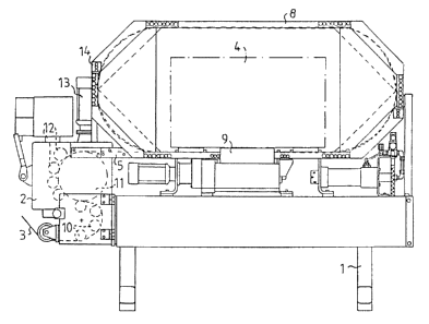
Fig. 1 shows a binding machine.
Fig. 2 shows the measuring means.

CA 02306394 2000-04-10
WO 98/58843 PCT/SE98/00941
3
The binding means is of the type shown and described in the patent SE 380 496
and in the
patent application SE 9303380-1.
The binding means comprises a stand 1 on which the various units are arranged.
A feeding
unit 2 is provided to feed binding wire 3 in the form of steel wire from a
wire magazine
around an object 4 to be bound and thereafter to stretch the wire.
A measuring means 5 is provided for continuously measuring the fed wire
length. The
measuring is carried out without the measuring means 5 feeding the wire.
The measuring means 5 preferably comprises a runner 6, which abuts the wire 3,
and a
preferably compressed-air loaded dolly roll 15 to ensure that the wire 3 and
runner 6 are in
contact with each other.
The runner 6 has a contact surface 16, preferably with substantially straight
profile. The
measuring result is thereby less depending on the wire quality and varying
contact pressure.
The runner 6 is coupled to a rotation meter 7, for example an inductive
transmitter or a
potentiometer, but preferably a pulse transmitter, which measures how much the
runner 6
has rolled and, thereby, how much wire has passed the measuring means 5.
A wire guide bar 8 extends about the object to be bound 4. A twining member 9
comprises
a guide bar for guiding the wire through the twining member, a unit for
locking the wire
end, a unit for tying a wire knot, a unit for cutting the wire, and a unit for
projecting the
completely tied knot.
The entire binding means preferably is movable so that it can be placed in a
transport path
for the objects to be bound and upon demand easily be exchanged.

CA 02306394 2000-04-10
WO 98/58843 PCT/SE98/00941
4
The feeding unit 2 comprises guide wheels 10, about which the wire 3 runs, and
a driven
feeding wheel 11, to which counter-pressure rolls 12 abut. The feeding wheel
11 preferably
is driven by an electric servomotor 13.
At the start of the binding machine the end of the wire 3 is positioned with
the help of the
values from the measuring means 5 to a pre-determined starting position for a
binding
sequence.
At the wire feed, the feeding unit 2 is driven by the electric servomotor 13,
so that a pre-
determined length of wire 3 is fed about the object to be bound 4, and the
wire end arrives
at the locking unit in the twining member 9. The fed wire length is measured
by the
measuring means 5. The wire end is retained in the twining member 9.
The wire stretching takes place thereafter by reversing the servomotor 13 of
the feeding unit
2 until the wire has been stretched down onto the object to be bound 4, and
the speed of the
wire is zero. The wire movement is measured, for example, by a pulse
transmitter in the
servomotor 13, but preferably by the measuring means 5.
The wire guide bar 8 is openable and provided with grooves for the wire 3.
During the wire
feed, the bar 8 is held in closed position by piston/cylinder units 14,
preferably pneumatic
ones. At the wire stretching, the wire guide bar 8 is opened by the
piston/cylinder units 14.
After the wire stretching, the units of the twining member 9 for twining,
cutting and
projecting the completed wire knot start to operate.
After the cutting, the wire is drawn back a predetermined length to the
starting position for
the next binding sequence by the feeding unit 2, which is controlled by values
from the
measuring means 5. The binding means is now ready for a new binding operation.

CA 02306394 2000-04-10
WO 98/58843 PCT/SE98/00941
The correct length of fed wire is ensured in that the wire 3 free of sliding
drives the runner
6 of the measuring unit which via the rotation meter 7 transfers the measuring
values for
controlling the wire feed. Since the moment of inertia in the runner 6 is
small in relation to
transferred moment between the wire 3 and runner 6, no sliding occurs between
the wire 3
and runner 6. The accuracy and operational safety of the binding means can in
this way be
increased. If in spite thereof sliding should occur, this would only mean that
a little too
much wire is fed, which does not negatively affect the operational safety.
The invention, of course, is not restricted to the embodiments shown, but can
be varied
within the scope of the claims with reference to the descriptive part and
drawing.

Representative Drawing
A single figure which represents the drawing illustrating the invention.
Administrative Status

For a clearer understanding of the status of the application/patent presented on this page, the site Disclaimer , as well as the definitions for Patent , Administrative Status , Maintenance Fee  and Payment History  should be consulted.

Administrative Status

Title Date
Forecasted Issue Date 2007-01-23
(86) PCT Filing Date 1998-05-20
(87) PCT Publication Date 1998-12-30
(85) National Entry 2000-04-10
Examination Requested 2003-03-17
(45) Issued 2007-01-23
Expired 2018-05-22

Abandonment History

There is no abandonment history.

Payment History

Fee Type Anniversary Year Due Date Amount Paid Paid Date
Registration of a document - section 124 $100.00 2000-04-10
Reinstatement of rights $200.00 2000-04-10
Application Fee $300.00 2000-04-10
Maintenance Fee - Application - New Act 2 2000-05-23 $100.00 2000-04-10
Maintenance Fee - Application - New Act 3 2001-05-21 $100.00 2001-04-27
Maintenance Fee - Application - New Act 4 2002-05-20 $100.00 2002-05-01
Request for Examination $400.00 2003-03-17
Maintenance Fee - Application - New Act 5 2003-05-20 $150.00 2003-05-01
Maintenance Fee - Application - New Act 6 2004-05-20 $200.00 2004-04-29
Maintenance Fee - Application - New Act 7 2005-05-20 $200.00 2005-04-29
Maintenance Fee - Application - New Act 8 2006-05-22 $200.00 2006-04-26
Final Fee $300.00 2006-11-10
Maintenance Fee - Patent - New Act 9 2007-05-22 $200.00 2007-05-11
Maintenance Fee - Patent - New Act 10 2008-05-20 $250.00 2008-04-25
Maintenance Fee - Patent - New Act 11 2009-05-20 $250.00 2009-04-27
Maintenance Fee - Patent - New Act 12 2010-05-20 $250.00 2010-05-10
Maintenance Fee - Patent - New Act 13 2011-05-20 $250.00 2011-05-16
Maintenance Fee - Patent - New Act 14 2012-05-21 $250.00 2012-05-07
Maintenance Fee - Patent - New Act 15 2013-05-21 $450.00 2013-05-06
Maintenance Fee - Patent - New Act 16 2014-05-20 $450.00 2014-05-09
Maintenance Fee - Patent - New Act 17 2015-05-20 $450.00 2015-04-17
Maintenance Fee - Patent - New Act 18 2016-05-20 $450.00 2016-04-18
Maintenance Fee - Patent - New Act 19 2017-05-23 $450.00 2017-04-28
Owners on Record

Note: Records showing the ownership history in alphabetical order.

Current Owners on Record
VALMET FIBERTECH AB
Past Owners on Record
EDSTROM, TOMAS
Past Owners that do not appear in the "Owners on Record" listing will appear in other documentation within the application.
Documents

To view selected files, please enter reCAPTCHA code :


To view images, click a link in the Document Description column. To download the documents, select one or more checkboxes in the first column and then click the "Download Selected in PDF format (Zip Archive)" or the "Download Selected as Single PDF" button.

List of published and non-published patent-specific documents on the CPD .

If you have any difficulty accessing content, you can call the Client Service Centre at 1-866-997-1936 or send them an e-mail at CIPO Client Service Centre.


Document
Description 
Date
(yyyy-mm-dd) 
Number of pages   Size of Image (KB) 
Drawings 2006-01-23 1 21
Description 2006-01-23 6 216
Claims 2006-01-23 3 91
Description 2000-04-10 5 172
Abstract 2000-04-10 1 50
Claims 2000-04-10 1 24
Drawings 2000-04-10 1 21
Representative Drawing 2000-06-14 1 12
Cover Page 2000-06-14 1 46
Representative Drawing 2006-08-24 1 14
Cover Page 2007-01-02 1 45
Assignment 2000-04-10 4 186
PCT 2000-04-10 8 289
Fees 2002-05-01 1 37
Prosecution-Amendment 2003-03-17 1 43
Prosecution-Amendment 2005-07-29 2 60
Prosecution-Amendment 2006-01-23 9 327
Correspondence 2006-11-10 1 38