Language selection

Search

Patent 2306529 Summary

Third-party information liability

Some of the information on this Web page has been provided by external sources. The Government of Canada is not responsible for the accuracy, reliability or currency of the information supplied by external sources. Users wishing to rely upon this information should consult directly with the source of the information. Content provided by external sources is not subject to official languages, privacy and accessibility requirements.

Claims and Abstract availability

Any discrepancies in the text and image of the Claims and Abstract are due to differing posting times. Text of the Claims and Abstract are posted:

  • At the time the application is open to public inspection;
  • At the time of issue of the patent (grant).
(12) Patent Application: (11) CA 2306529
(54) English Title: CABLE SIMULATOR
(54) French Title: SIMULATEUR DE CABLE
Status: Dead
Bibliographic Data
(51) International Patent Classification (IPC):
  • H04B 3/40 (2006.01)
  • H04N 7/10 (2006.01)
(72) Inventors :
  • LOUISE, WILLIAM (United States of America)
(73) Owners :
  • EAGLE COMTRONICS, INC. (United States of America)
(71) Applicants :
  • EAGLE COMTRONICS, INC. (United States of America)
(74) Agent: DIMOCK STRATTON CLARIZIO LLP
(74) Associate agent:
(45) Issued:
(22) Filed Date: 2000-04-25
(41) Open to Public Inspection: 2000-10-26
Examination requested: 2000-04-25
Availability of licence: N/A
(25) Language of filing: English

Patent Cooperation Treaty (PCT): No

(30) Application Priority Data:
Application No. Country/Territory Date
60/130,951 United States of America 1999-04-26
09/556,073 United States of America 2000-04-21

Abstracts

English Abstract


A cable simulator includes an inductor, a capacitor, and two resistors
connected to provide low attenuation on low frequency (50 MHZ and below)
signals
and increasing attenuation with increasing frequency. The simulator provides a
broadband impedance match.


Claims

Note: Claims are shown in the official language in which they were submitted.


What is claimed is:

1. A cable simulator circuit, comprising:
an input;
an output;
an inductor;
first and second resistors;
said inductor and said first and second resistors being connected in parallel
between said input and said output; and
a capacitor having one end connected between said first and second resistors
and another end connected to ground.

2. A cable simulator according to claim 1, wherein said first and second
resistors
are of equal resistance.

3. A cable simulator according to claim 1, wherein a capacitance of said
capacitor equals 2.2 pF, an inductance of said inductor equals 22 nH, and said
first
and second resistors each have a resistance equal to 75 ohms.

4. A cable simulator according to claim 2, wherein a capacitance of said
capacitor equals 2.2 pF, an inductance of said inductor equals 22 nH, and said
first
and second resistors each have a resistance equal to 75 ohms.

5. A cable simulator according to claim 1, wherein said cable simulator
circuit is
encased in a housing wherein said housing includes a first cable connector
connected
to said input and a second cable connector connected to said output.

6. A cable simulator according to claim 2, wherein said cable simulator
circuit is
encased in a housing wherein said housing includes a first cable connector
connected
to said input and a second cable connector connected to said output.

-4-

Description

Note: Descriptions are shown in the official language in which they were submitted.


CA 02306529 2000-04-25
CABLE SIMULATOR
CROSS-REFERENCE TO RELATED APPLICATIONS
This application claims priority from U.S. Provisional Application Serial No.
60/130,951 entitled CABLE SIMULATOR filed on April 26, 1999, incorporated
S herein by reference.
FIELD OF THE INVENTION
The invention pertains to the field of broadband impedance matching, and in
particular, to the field of cable simulators for simulating a specified length
of cable.
BACKGROUND OF THE INVENTION
In cable television systems that are running 2-way transmissions, there is a
loss differential which depends on the direction of the signal. The cable
plant is
designed around the forward properties (50 MHz-750 MHZ) of the distribution
equipment, i.e., amplifiers, taps, and cable so that the drop level remains a
constant
about a given design level.
1 S Reverse path signals experience lower signal losses than forward signals
due
to the low frequencies used (5 MHz-40 MHZ). Since the system is designed for
the
forward signal, there is more amplification at the higher frequencies which is
overcome by the distribution equipment losses. In those cases where
distribution
equipment is close to an amplifier, cable system operators have found that
they need
to attenuate the higher frequencies and not the lower frequencies. Only those
modem
connections closest to an amplifier or line extender have this need. The
operators
have found that using 100 feet of coaxial cable right before the modem
effectively
attenuates the forward path without significantly impacting the reverse path.
There
are problems with simply adding 100 feet of coaxial cable to an installation,
such as
the time involved and the need to hide 100 feet of coiled cable at a user's
location.
Accordingly, an alternate solution is required.
-1-


CA 02306529 2000-04-25
SUMMARY OF THE INVENTION
Briefly stated, a cable simulator includes an inductor, a capacitor, and two
resistors connected to provide low attenuation on low frequency (50 MHZ and
below)
signals and increasing attenuation with increasing frequency. The simulator
provides
a broadband impedance match.
According to an embodiment of the invention, a cable simulator circuit
includes an input; an output; an inductor; first and second resistors; said
inductor and
said first and second resistors being connected in parallel between said input
and said
output; and a capacitor having one end connected between said first and second
resistors and another end connected to ground.
BRIEF DESCRIPTION OF THE DRAWINGS
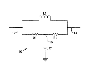
Fig. 1 shows a schematic diagram of a cable simulator according to the present
invention.
Fig. 2 shows a housing for the cable simulator of the present invention.
DETAILED DESCRIPTION OF THE PREFERRED EMBODIMENT
Referring to Fig. 1, a cable simulator 10 includes an input 12 and an output
14.
An inductor L1 is in parallel with two equal resistors R1. One end of a
capacitor C1
is connected at 16 between the two resistors Rl, and the other end is
connected to
ground. To simulate 100 feet of RG-6A/U cable, the following values are used:
L 1 = 22 nH
C 1 = 2.2 pF
Rl = 75 S2
These values can be varied to simulate other lengths and types of cable. To
obtain the
component values, a simulation program such as Genesys, Touchstone, or
Microwave
Office is used. The program is used to optimize the cable simulator response
curve to
match approximately the values for the desired cable attenuation.
Cable simulator 10 has low attenuation on low frequency signals, i.e., 50 MHz
and below, with increasing attenuation with increasing frequency. The
difference
between simulator 10 and a low pass filter is that simulator 10 provides a
broadband
-2-


CA 02306529 2000-04-25
impedance match whereas the low pass filter is reflective in its stopband.
Inductor L1
allows low frequencies to pass through the device with little loss while
impeding
some of the higher frequencies. Resistors Rl match the circuit to the system
impedance for good return loss. Capacitor C1 shunts off some of the high
frequencies
to ground. The capacitor to inductor ratio determines the slope of the cable
simulator.
Referring to Fig. 2, cable simulator 10 fits inside a housing 20. Housing 20
is
approximately 1.6 inches long and 0.8 inches in diameter. Cable compatible
connectors 22, 24 on each end of housing 20 facilitate connecting cable
simulator in
line with a cable. Cable simulator 10 is preferably of discrete components on
a
printed circuit board. A ground cable connects the circuit to the outside of
housing
20. Housing 20 is preferably a standard filter tube housing with connectors
22; 24
built into the housing.
While the present invention has been described with reference to a particular
preferred embodiment and the accompanying drawings, it will be understood by
those
skilled in the art that the invention is not limited to the preferred
embodiment and that
various modifications and the like could be made thereto without departing
from the
scope of the invention as defined in the following claims.
-3-
Representative Drawing
A single figure which represents the drawing illustrating the invention.
Administrative Status

For a clearer understanding of the status of the application/patent presented on this page, the site Disclaimer , as well as the definitions for Patent , Administrative Status , Maintenance Fee  and Payment History  should be consulted.

Administrative Status

Title Date
Forecasted Issue Date Unavailable
(22) Filed 2000-04-25
Examination Requested 2000-04-25
(41) Open to Public Inspection 2000-10-26
Dead Application 2003-08-05

Abandonment History

Abandonment Date Reason Reinstatement Date
2002-08-05 R30(2) - Failure to Respond
2003-04-25 FAILURE TO PAY APPLICATION MAINTENANCE FEE

Payment History

Fee Type Anniversary Year Due Date Amount Paid Paid Date
Request for Examination $400.00 2000-04-25
Application Fee $300.00 2000-04-25
Registration of a document - section 124 $100.00 2000-06-14
Maintenance Fee - Application - New Act 2 2002-04-25 $100.00 2002-04-03
Owners on Record

Note: Records showing the ownership history in alphabetical order.

Current Owners on Record
EAGLE COMTRONICS, INC.
Past Owners on Record
LOUISE, WILLIAM
Past Owners that do not appear in the "Owners on Record" listing will appear in other documentation within the application.
Documents

To view selected files, please enter reCAPTCHA code :


To view images, click a link in the Document Description column. To download the documents, select one or more checkboxes in the first column and then click the "Download Selected in PDF format (Zip Archive)" or the "Download Selected as Single PDF" button.

List of published and non-published patent-specific documents on the CPD .

If you have any difficulty accessing content, you can call the Client Service Centre at 1-866-997-1936 or send them an e-mail at CIPO Client Service Centre.


Document
Description 
Date
(yyyy-mm-dd) 
Number of pages   Size of Image (KB) 
Drawings 2000-04-25 1 7
Description 2000-04-25 3 125
Claims 2000-04-25 1 35
Abstract 2000-04-25 1 9
Representative Drawing 2000-10-16 1 3
Cover Page 2000-10-16 1 20
Correspondence 2000-06-02 1 2
Assignment 2000-04-25 4 99
Correspondence 2000-06-14 3 83
Assignment 2000-06-14 3 114
Assignment 2000-04-25 6 151
Correspondence 2000-08-14 1 1
Prosecution-Amendment 2002-04-05 2 51
Fees 2002-04-03 1 35