Note: Descriptions are shown in the official language in which they were submitted.
CA 02306696 2000-04-26
1 P/61792/MAD
Improvements in or Relating to Combiner Assemblies
The present invention relates to combiner assemblies having a combiner through
which a
user views an outside scene overlaid with a projected image. Such combiner
assemblies
can be used in head up displays.
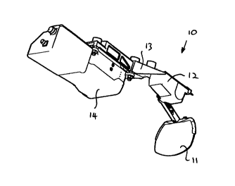
Figure 1 illustrates a typical combiner assembly 10 used in a head up display,
which
comprises an optical combiner 11 mounted to a housing 12 which is arranged for
mounting
to a roof structure 13 of a flight deck of an aircraft. The combiner assembly
10 comprises
a semi-reflective surface and is arranged to present flight, navigation,
guidance and other
information to a user who views an outside scene through the optical combiner
11. This is
accomplished by projecting images from a display forming section 14, typically
comprising
a cathode ray tube, onto the semi-reflective surface which is arranged to
allow the user to
view the outside scene through the optical combiner 11 and to reflect the
images from the
display forming section 14 along a sight line of the user. The image conveyed
to the user
is collimated and conformal such that the user views the outside scene
overlaid with the
projected images. Typically, the optical combiner 11 is pivotally mounted, not
illustrated,
to the housing 12 such that the optical combiner 11 can be moved from a stowed
position
above the user's head to a deployed position in front of the user and
coincident with the
user's sight line.
However, if the optical combiner 11 is not properly secured in the stowed
position it may
rotate from its position such that it interferes with the user's vision, or
worse, impacts the
CA 02306696 2000-04-26
2 PI61792/MAD
user's head. Furthermore, should the user move forward while the optical
combiner 11 is
in the deployed position, perhaps due to the aircraft flying into turbulent
air, and impacts
the optical combiner 11 then this could interfere with the safe and proper
handling of the
aircraft.
It is an object of the present invention to provide a combiner assembly which
obviates or
mitigates the problems associated with the prior art.
According to the present invention, a combiner assembly comprises an optical
combiner,
a housing and a mounting assembly arranged to connect the optical combiner to
the
housing, wherein the optical combiner is arranged to rotate around the housing
and the
mean distance between the combiner and the housing varies with the angular
rotation of the
combiner around the housing.
In this manner, the optical combiner rotates around the housing such that it
traverses a path
wherein the mean distance between the optical combiner and the housing varies
as the
optical combiner rotates from a stowed position to a deployed position,
through which the
user can view a scene, and from the deployed position back to the stowed
position, thereby
reducing the risk of the combiner coming into contact with the user as the
combiner moves
to or from the stowed position.
Preferably, the mounting assembly may comprise a first arm pivotally mounted
at one end
to the optical combiner at a first pivot point and pivotally mounted at the
other end to the
CA 02306696 2000-04-26
3 P/61792/MAD
housing at a second pivot point to provide rotational movement of the optical
combiner
around the housing, a second arm pivotally mounted at one end to the optical
combiner at
a third pivot point and pivotally mounted at the other end to the housing at a
fourth pivot
point to provide rotational movement of the optical combiner around the
housing and the
first and second arms are positioned in a non-parallel arrangement.
In this manner, the optical combiner rotates around the pivot points such that
its tip, that
end remote to the first and third pivot points, traverses a path wherein the
mean distance
between the optical combiner and the housing varies as the optical combiner
rotates from
a stowed position to a deployed position, through which the user can view a
scene, and from
the deployed position back to the stowed
At least one of the arms may be arranged to be adjustable in length to
facilitate setting the
angular position of the optical combiner.
Preferably, the optical combiner may be arranged to move between stowed and
deployed
positions and the pivot points are arranged so that the optical combiner
traverses a locus,
wherein on at least one point of the locus the optical combiner is located
closer to the
housing than the optical combiner is when located in either the stowed or
deployed
positions.
The pivot points may be arranged to allow the optical combiner to rotate down
into the
deployed position at which point the user views the scene.
CA 02306696 2000-04-26
4 P/61792/MAD
Preferably, the pivots may be arranged to allow the optical combiner to rotate
past the
deployed position to a further position thereby to allow a degree of movement
for the
optical combiner should a user impact the optical combiner. The second arm may
be a strut
comprising a spring arranged to allow the optical combiner to rotate past the
further
position thereby to allow a further degree of movement for the optical
combiner should a
user impact the optical combiner.
The invention will now be described, by way of example only, with reference to
the
accompanying drawings, in which:
Figure 1 illustrates generally a combiner assembly according to the prior art;
Figure 2 illustrates a combiner assembly in elevation view;
Figure 3 schematically illustrates the movement of a combiner, as illustrated
in Figure 2,
from a deployed position to a stowed position;
Figure 4 schematically illustrates the movement of a combiner about various
pivot points
when the combiner is moved from a deployed position to a stowed position, and
Figure 5 illustrates in elevation view further positions for a combiner, as
illustrated in
Figure 2.
In Figure 2, a combiner assembly 20 comprises an optical combiner 21 mounted
to a
housing 22 using a mounting assembly which is arranged for mounting to a roof
structure,
not shown, of a flight deck of an aircraft. The combiner assembly 20 is
arranged to present
flight, navigation, guidance and other useful information to a user who also
views a scene,
CA 02306696 2000-04-26
P161792/MAD
typically a scene outside the aircraft, through the combiner 21, that is the
combiner 21
provides a head up display, as discussed with reference to Figure 1. The
combiner 21 is
mounted within a frame 23 which is arranged to be mounted to the housing 22.
The
combiner 21 comprises a suitable material such as glass which is capable of
reflecting
5 images generated by a display forming section, not illustrated, along a
sight line to the user
of the combiner 21, such that the user will perceive the scene overlaid with
images
generated by the display forming section and reflected by the combiner 21. The
image
conveyed to the user is collimated and conformal with other design parameters
considered
when manufacturing a combiner assembly 20.
The frame 23 of the combiner assembly 20 has a first pivot point 24 which is
attached to
a first arm 25 which is also attached to the housing 22 at a second pivot
point 26 located at
a position remote from the first pivot point 24. The first arm 25 is arranged
to allow the
combiner 21 to rotate about the housing 22 between a deployed position, as
shown in Figure
2, and a stowed position, not illustrated.
A second arm 27 is pivotally connected to the frame 23 at a third pivot point
28, at a
position spaced from the first pivot point 24, and to the housing 22 at a
fourth pivot point
29, located at a position remote from the third pivot point 28 and at a
position spaced from
the second pivot point 26. The second arm 27 may take the form of a spring
bias strut. It
will be understood that the first and second arms 25, 27 constitute the
mounting assembly
connecting the combiner 21 to the housing 22.
CA 02306696 2000-04-26
6 P/61792/MAD
The pivot points 24, 26, 28 and 29 are arranged in such a manner that the
first and second
arms 25, 27 are positioned in a non-parallel arrangement so that the combiner
21 traverses
a pathway wherein the mean distance between the combiner 21 and the housing 22
varies
during rotational movement about the pivots 24, 26, 28 and 29 when the
combiner 21 is
moved between a deployed position, shown in Figure 2, and a stowed position,
not
illustrated. Furthermore, when the combiner 21 is moved from the stowed
position to the
deployed position the combiner 21 will return to a repeatable accurate
location.
From Figure 3, in which like references have been used to indicate similar
integers to those
referenced in Figure 2, a user 30 of the combiner 21 views images projected
from a display
forming section, not illustrated, along a sight line 31, which are overlaid on
a scene, not
illustrated, viewed through the combiner 21. The combiner 21 is moveable along
the
pathway between a combiner 21 position shown as solid lines in a deployed
position and
a combiner 21a position illustrated by dotted lines in a stowed position. As
the pathway
formed by the rotation of the combiner 21 around the housing 22 forms a locus
wherein on
at least one point of the locus the combiner 21 is closer to the housing 22
than the combiner
21 is when located in either the stowed or deployed positions, greater
clearance is provided
as the tip of the combiner 21, that end remote to the first and third pivot
points 24 and 28,
as it passes at its nearest point to the user 30 when the combiner is moved
between the
deployed and stowed positions.
Referring back to Figure 2, the first arm 25 also carries a cooperating pair
of release
mechanisms 32 and 33 which cooperate to latch the combiner 21 in either the
stowed or the
CA 02306696 2000-04-26
7 P/61792/MAD
deployed positions. The combiner 21 is shown in the deployed position. A user
operates the
release mechanism 33 to delatch the combiner 21 so that the user may move the
combiner
21 from the deployed position to the stowed position. When in the stowed
position the user
operates release mechanism 32, which cooperates with release mechanism 33, to
delatch
the combiner 21 so that it may be dropped under gravity to the deployed
position.
As illustrated in Figure 2, the first and second arms 25 and 27 may be
considered a pair of
non-parallel links 34 and 35, respectively, and the space between the first
and third pivot
points 24 and 28 may be considered to be a third link 36. The movement of
these links 34,
35, and 36 is illustrated in Figure 4, in which like references have been used
to indicate
similar integers as those referenced in Figure 2. The movement of the links
34, 35 and 36
ensures that the tip of the combiner 21 follows a pathway wherein the mean
distance
between the housing 22 and the combiner 21 varies with angular rotation of the
combiner
21 about the housing 22 such that more clearance is provided between the tip
of the
combiner 21 and the head of a user.
The locus 37 formed by the movement of the tip of the combiner 21 is indicated
in Figure
3 as a chained line, where it can be seen that the locus 37 provides greater
headroom for the
user 30 than would normally be present for a combiner 21 that merely pivots
about a pivot
point following a radial pathway 38, indicated as a double chained line, when
moving
between deployed and stowed positions.
A further advantage of the combiner assembly 20, as best shown in Figure 3, is
that should
CA 02306696 2000-04-26
8 P161792/MAD
the combiner 21 not be properly latched in the stowed position and should it
fall from this
position, then it is less likely to impact the head of the user 30 and
movement from this
position will indicate to the user 30 that it has not latched in the correct
stowed position.
The user 30 can then move the combiner 21 back to a proper latched stowed
position.
Figure 5, in which like references have been used to indicate similar integers
to those
referenced in Figure 2, illustrates that should a user of the combiner 21
accidentally or
otherwise impact the combiner 21, it will rotate about the second pivot point
26 from the
position shown in solid lines to a more forward position 21b indicated by
dotted lines where
it is retained by a detent arrangement within the housing 22 until the user
returns the
combiner 21 to its original position. The detent arrangement may be arranged
to allow the
combiner 21 to move forward but only to the aircraft's airframe limits to
prevent damage
to either the airframe, which may be glass, or the combiner 21.
Furthermore, if, while the combiner 21 is in the forward position 21b, the
user further
impacts the cpmbiner 21, a spring, not illustrated, associated with the second
arm 27 will
allow the length of arm 27 to extend thereby allowing the combiner 21 to
rotate about the
first pivot point 24 to a further position 21c indicated by chained lines.
Once the user stops
applying pressure to the combiner 21 it will return under the bias of the
spring to the
position indicated by 21b and can only be returned to a proper deployed
position 21 when
the user so moves it to that position. Preferably, the spring is housed within
the second arm
27. These features reduce the injurious effects on the user due to impact with
the combiner
21 by cushioning the blow since the combiner 21 is able to rotate to more
forward positions
CA 02306696 2000-04-26
9 P/61792/MAD
either 21 b or 21 c.
The combiner assembly 20 may also comprise switching means to ensure that
should the
combiner 21 be moved to forward position 21b that the display forming section,
not shown,
will be switched off such that spurious images are not projected onto the
combiner 21
which could be misread due to the misalignment of the combiner 21. This can be
achieved
by arranging a switch and cam arrangement or an electronic device within the
housing 22
such that when the combiner 21 moves to the more forward position 21b,
rotation of the
first arm 25 about the second pivot point 26 also causes the cam arrangement
to rotate and
operate the switch or electronic device so as to prohibit images, from the
display forming
means, from being projected to the combiner 21.
Preferably, the switch is a micro switch that is mounted in a groove within
the housing 22
and is operable when the first arm 25 rotates about the second pivot point. In
this manner
the micro switch can be retained within the housing 22 so as to form a more
compact
combiner assembly 20 in an environment in which space is limited.
As best illustrated in Figure 3, the combiner assembly 20 when in a stowed
position does
not protrude into the user's 30 head space thereby providing greater head room
for the user
30 and mitigating the possibility of the user's 30 head impacting against part
of the
combiner assembly 20 when the user 30 reaches forward.
From Figure 2, the housing 22 can be mounted on a mounting plate 38 which is
further
CA 02306696 2000-04-26
P/61792/MAD
mounted to the roof structure of the flight deck,such that adjustment screws
39 associated
with the mounting plate 38 can be manipulated to allow alignment of the
combiner 21 in
rotation, sideways, fore and aft directions. Furthermore, the frame 23
retaining the combiner
21 may also allow adjustment of the combiner 21 to allow alignment of the
combiner 21
5 in elevation. Adjustments of the combiner assembly 20 can be completed on a
purpose
built optical alignment jig prior to mounting of the combiner assembly 20 in
the aircraft or
in the aircraft while the combiner assembly 20 is in situ. In the former case,
the combiner
assembly 20 will not require further adjustment after installation and this
will also allow
combiner assemblies 20 to be readily interchangeable.
It will be understood that although the combiner assembly 20 is described with
reference
to a head up display for an aircraft, it is envisaged that the combiner
assembly 20 could be
used in alternative means of transport or other environments in which
information needs
to be conveyed to a user and overlaid on the user's view of a forward scene.