Note: Descriptions are shown in the official language in which they were submitted.
CA 02307038 2000-02-07
TORQUE TRANSDUCER
TECHNICAL FIELD
PC'f/AU98/00645
Received 12 November 1999
This invention relates to torque transducers for measuring the magnitude of
torque in
shafts, in particular rotating shafts such as found in electric power steering
systems in
vehicle applications.
BACKGROUND
Electric power steering systems conventionally incorporate an input shaft
element,
connected via an intermediate shaft and Hookes joint arrangement to the
steering wheel.
to The input shaft therefore needs to rotate through an angle typically one to
two
revolutions either side of the on-centre steering position. The input shaft is
at least
partially surrounded by the fixed housing of the steering gear. It is a
requirement of the
electric power steering servo system to accurately measure the continuously
varying
torque in this rotating shaft. Conventionally torque applied to the shaft
causes it to
is angularly deflect, such deflection causing one part of the shaft to
angularly displace with
respect to another part, and this displacement is sensed to provide a
measurement of
this torque.
The sensing means needs to allow for rotation of the shaft within the housing,
usually
employing non-contact or mechanical signal transmission means. Non-contact
means
2o include optical aperture based devices and magnetic devices such as
magnetostrictive or
variable reluctance couplings. Mechanical means include slidably connected
potentiometers and other indicating devices.
To improve the accuracy of such sensing means a torsionally compliant coupling
in the
form of a torsion bar is used to connect the two input members at either end
of the shaft.
2s When torque is applied between the two input members the torsion bar
deflects causing
an increased angular displacement, which allows the use of less sensitive, or
less
accurate sensing means.
The torsion bar may be in the~o~of_a separate element as in the case of a
conventional rotary hydraulic power steering valve. Alternatively, in the case
of some
AMENDED SHEET
~F~ALcIU
CA 02307038 2000-02-07
PCT/AU98/00645
Received 12 November 1999
proposed electric power steering systems, the torsion bar may in fact be
integral with the
shaft member and be a relatively torsionally compliant (ie. less torsionally
stiff) portion of
the shaft member which couples substantially rigid torque input members at
each end of
the shaft member. The shaft member in these latter systems can be readily
machined as
a single steel component, and the only requirement is that the angular
deflection of the
relatively torsionally compliant coupling portion, connecting the two
substantially rigid
torque input member portions, has sufficiently low torsional stiffness that
the sensing
system is able to accurately measure its angular deflection.
io Generally, the use of a torsion bar requires the use of a failsafe
mechanism, being a
torque limiting device to prevent failure of the torsion bar when unavoidable
torque
overload conditions occur.
Such torque limiting devices are well known in the art of vehicle steering,
and will
therefore not be described in this specification.
is The prior art, which is most closely related to that of the present
invention, is described in
US Patent 5,369,583 and International Patent Application PCT/GB95/02017 which
show
sensors employing optical disc apertures for measuring torque.
The essence of the present invention resides in the provision of grating
elements
comprising surfaces composed of alternating regions of high and low
reflectivity
2o connected by a torsionally compliant coupling. These surfaces are
illuminated by a
source of electro-magnetic radiation (EMR), typically UV, visible or IR light,
which
generates patterns on one or more arrays of detectors sensitive to the EMR.
Arrays
include CCD devices, VLSI vision chips, one and 2 dimensional photodetector
arrays
and lateral effect photodiodes (commonly referred to as PSD's or position
sensitive
Zs devices). The disposition of the patterns is a function of torque applied
to the shaft, and
the output of the one or more arrays can be processed to produce a measure of
the
torque applied to the shaft. It is distinguished from other reflective torque
transducers by
use of an reflective imaging approach which does not rely on Moire fringes,
speckle
patterns or other diffraction gratings. As it uses photo detector arrays, EMR
reflected
3o from the gratings provide an instantaneous image which allows a much faster
and more
~E~1~ED SHEET
WFRIAU
CA 02307038 2000-02-07
3
PCT/AU98/00645
Received 12 November 1999
complete means of interpreting the information than is possible with
individual photo-
detectors. In the latter case it is necessary to count successive changes of
EMR intensity
incident on the photo-detector, which is slower and more prone to error.
s Another reflective torque transducer that uses arrays is described in US
patent
5,490,430. This relies on a change in diffraction angle of two or more
diffraction gratings
that are torsionally strained by the application of torque. This device is
prone to error due
to misalignment and bending load and requires a collimated and monochromatic
source
of EMR. The regions of high and low reflectivity can be arranged axially or
radially about
to the axis of rotation of the shaft, and are of such a nature that allows a
continuous output
of the arrays at any instant in time regardless of the angular position of the
shaft, as the
limited array dimensions may not allow the complete circumference or radial
face to be
viewed by the arrays. The advantages of such a construction over that
disclosed in U.S.
Patent 5,369,583 and International Application Number PCT/GB95/02017 may arise
as
t s one or more of the following:
Firstly, the use of reflective grating elements allows simpler and more
compact
construction by the use of a cylindrical grating element arrangement, which is
not readily
achievable using disc apertures as shown in the prior art without requiring a
significantly
increased diameter. It also allows the EMR sources) and arrays) to be packaged
in the
2o same assembly with further savings in space and cost. Secondly, it allows
for easy
assembly and disassembly of the transducer, as the grating elements can be
removed
from one end of the transducer in an axial direction without disturbing the
EMR sources)
or array(s).
Thirdly, another advantage with the use of reflective grating elements is that
the EMR is
2s reflected from the surface, and is not affected by edge scattering as is
the case with
apertures with a non-zero thickness. Such scattering limits the maximum
resolution of
the device.Fourthly, the use of reflective grating elements allows the use of
well known
and accurate photographic or m.~~.allising techniques, for example metal on
glass. The
use of these techniques with apertures may result in loss of resolution or
other problems
~~~ti~~C~ SHEET'
~E~a~au
CA 02307038 2000-02-07
PC'f/AU98/00645
Received 12 November 1999
4
from internal reflection, diffraction or degradation over time as the EMR has
to travel
through the glass between the metallised regions.
Finally, the use of reflective grating elements allow the use of intermeshed
castellations
which can provide a lost motion connection limiting the maximum angular
deflection of
the torsion bar, thereby eliminating the need for a separate torque limiting
device and
reducing the cost and complexity of the transducer.
DISCLOSURE OF INVENTION
The present invention consists in a torque transducer comprising a rotating
shaft at least
partially surrounded by a fixed housing, the axis of rotation of the shaft
fixed with respect
to the housing, the shaft comprising first and second substantially rigid
torque input
members which are connected by a torsionally compliant coupling, the coupling
thereby
Is enabling angular deflection of the first torque input member relative to
the second torque
input member as a function of the magnitude of the torque in the shaft, a
first grating
element attached to or integral with the first torque input member and a
second grating
element attached to or integral with the second torque input member, the first
grating
element comprising a first surface and the second grating element comprising a
second
2o surface, the transducer also comprising one or more electro-magnetic
radiation (EMR)
sources and one or more arrays of EMR sensitive detectors, characterised in
that each
source irradiates one or both of the surfaces and each array receives incident
EMR
reflected from one or both of the surfaces, the one or more sources
irradiating each
surface and the one or more arrays receiving incident EMR reflected from this
surface
2s are all positioned in the same side of this surface and fixed with respect
to the housing,
both surfaces comprise alternating regions of high and low reflectivity, a
pattern
produced by incident EMR on each of the one or more arrays at any instant of
time
resulting from the alternating_~egi~nsof low and high reflectivity on the one
or both
surfaces providing reflected EMR to this array regardless of the angular
position of the
3o shaft and irrespective of the relative angular deflection of the first and
second torque
~E~~E~ SHEE'~
tP~I,~U
CA 02307038 2000-02-07
PCT/AU98/0064s
Received 12 November 1999
input members, the output from the one or more arrays, resulting from the
pattern or
patterns on the one or more arrays at said any instant of time, is processed
by a
processor to derive the relative angular deflection of the first and second
torque input
members, and hence provide a measure of the magnitude of the torque in the
shaft.
In some embodiments of the present invention a first array receives incident
EMR
reflected from a first surface and results in a first pattern, and a second
array receives
incident EMR reflected from a second surface and results in a second pattern.
It is
preferred that the processor receives inputs from the first and second arrays,
and the
to processor comprises software or hardware electronic means to determine the
relative
displacement of the first and second patterns.
In other embodiments of the present invention the first and second surfaces
are either
mutually adjacent or contiguous, a single array receives incident EMR
reflected from
both first and second surfaces and results in a single pattern, the pattern
comprises a
Is first subpattern produced by the incident EMR reflected from the first
surface and a
second subpattern produced by the incident EMR reflected from the second
surface. It is
preferred that the processor receives inputs from the single array, and the
processor
comprises software or hardware electronic means to determine the relative
displacement
of the first and second subpatterns. It is preferred that the single pattern
is an interdigital
2o pattern comprising the first subpattern interposed between the second
subpattern.
It is preferred that at least one of first or second surfaces is substantially
cylindrical with a
central axis collinear with the axis of rotation of the shaft, and the array,
which receives
incident EMR reflected from the at least one surface, is positioned radially
inside or
outside the surface. It is preferred that the at least one substantially
cylindrical surface is
2s discontinuous due the respective grating element comprising radially
protruding
castellations around its periphery, the castellations are substantially
axially aligned, the
regions of high reflectivity correspond to the areas of maximum radius of the
castellations
with respect to the central axis-~f the cylindrical surface, and the regions
of low
reflectivity are angularly aligned with the discontinuous gap areas or lesser
radius areas
3o between the castellations. Also it is preferred that the grating element is
manufactured
~~«~~~ SHEET
~~~r,~u
CA 02307038 2000-02-07
WO 99/09385 PCT/AU98/00645
from metal or plastic material and the areas of maximum radius are smoothly
machined,
moulded or sintered, or surface treated with paint or material deposition to
impart high
reflectivity, and the discontinuous gap areas or lesser radius areas are
machined,
moulded or sintered, or surface treated with paint or material deposition to
impart low
reflectivity.
Alternatively, in certain applications, it may be preferred that the at least
one substantially
cylindrical surface is substantially continuous due to the respective grating
element
io comprising a substantially smooth cylinder, the inside or outside surface
of the cylinder
comprising the alternating regions of high and low reflectivity, and the
regions are
substantially axially aligned. Preferably the regions of high reflectivity are
metallised,
shiny or light coloured and the regions of low reflectivity are substantially
transparent,
roughened or dark coloured.
~s
Alternatively, in certain applications, it may be preferred that the at least
one of first or
second surtaces is substantially radially disposed with respect to the axis of
rotation of
the shaft, and the array, which receives incident EMR reflected from the at
least one
surface, is positioned axially on one side of the surface. Preferably, the at
least one
2o substantially radially disposed surface is discontinuous due to the
respective grating
element comprising axially protruding castellations around its periphery, the
castellations
are substantially radially disposed, the regions of high reflectivity
correspond to the areas
of maximum axial protrusion of the castellations, and the regions of low
reflectivity are
angularly aligned with the discontinuous gap areas or less axially protruding
areas
2s between the castellations. Also it is preferred that the grating element is
manufactured
from metal or plastic material, the areas of maximum axial protrusion are
smoothly
machined, moulded or sintered, or surface treated with paint or material
deposition to
impart high reflectivity, and the discontinuous gap areas or less axially
protruding areas
are machined, moulded or sintered, or surface treated with paint or material
deposition to
so impart low reflectivity.
Alternatively, in certain applications, it may be preferred that the at least
one substantially
CA 02307038 2000-02-07
WO 99/09385 PCT/AU98/00645
7
radially disposed surface is substantially continuous due to the respective
grating
element comprising a substantially smooth disc or planar ring, one side of the
disc or
planar ring comprising the alternating regions of high and low reflectivity,
the regions are
substantially radially disposed, the regions of high reflectivity are
metallised, shiny or light
coloured, and the regions of low reflectivity are substantially transparent,
roughened or
dark coloured.
Preferably the array comprises a one dimensional or a two dimensional array, a
CCD, a
to VLSI vision chip or a lateral effect photodiode.
Preferably the pattern or patterns is also processed by a processor to derive
angular
velocity and/or the relative angular position of at least one of the torque
input members.
Preferably the surface of at least one grating element includes areas or
additional
is regions of high or low reflectivity whose resulting pattern is also
processed to derive
absolute angular position of the torque input member to which the at least one
grating
element is attached to or integral with.
Preferably the alternating regions of high and low reflectivity on the surface
of the at least
ao one grating element are arranged in the form of a succession of individual
binary bar
codes arranged such that the individual bar codes do not overlap.
Alternatively the
alternating regions of high and low reflectivity on the surface of the at
least one grating
element are arranged in the form of a succession of individual bar codes
arranged such
that the individual bar codes overlap. The resulting pattern on the respective
array is
2s processed to derive the absolute angular position of the torque input
member to which
the at least one grating element is attached to or integral with. It is
preferred that a
succession of binary bar codes are employed on both grating elements and the
difference in the absolute angular position of the first and second torque
input members
is used to provide a measure of the magnitude of the torque in the shaft.
Preferably the first and second grating elements are adjacent and comprise
radially
CA 02307038 2000-02-07
WO 99/09385 PCT/AU98/00645
8
extending intermeshing castellations, clearance being provided between the
castellations
and thereby providing a rotational lost motion connection between the first
and second
torque input members and hence limiting the maximum angular deflection of the
s torsionally compliant coupling.
BRIEF DESCRIPTION OF DRAWINGS
The present invention will now be described by way of example with reference
to the
to accompanying drawings, in which:
Fig. 1 is a diagrammatic view of two torque input members connected by a
torsion
bar, showing the regions of high and low reflectivity on the surfaces of the
grating
elements and the associated two arrays,
Fig. 2 is a cross section of torque transducer according to a first embodiment
of
is the present invention based on the concept shown in Fig. 1,
Fig. 3 is a diagrammatic view of two torque input members connected by a
torsion
bar, showing the regions of high and low reflectivity on the surfaces of the
adjacent
grating elements and the associated single array,
Fig. 4 is an exploded isometric view of an interdigital arrangement of two
grating
zo elements comprising castellations,
Fig. 5 is another view of Fig. 4 showing the actual relationship of the two
grating
elements and the associated single array,
Fig. 6 is cross section of a torque transducer according to a second
embodiment
of the present invention, based on the concept shown in Figs. 4 and 5,
2s Fig. 7 is a cross section of the failsafe mechanism in the embodiments
shown in
Figs. 2, 6, 8, 11, 12 and 16,
Fig. 8 is a cross section of a torque transducer according to a third
embodiment of
the present invention, utilising grating elements comprising substantially
smooth
cylindrical surfaces,
3o Fig. 9 shows details of the grating elements of the torque transducer shown
in Fig.
8,
Fig. 10 is a diagrammatic view similar to Fig. 1 but showing grating elements
with
CA 02307038 2000-02-07
WO 99/09385 PCT/AU98/00645
9
radially disposed surfaces,
Fig. 11 is a cross section of torque transducer according to a fourth
embodiment
of the present invention, based on the concept shown in Fig. 10,
s Fig. 12 is a cross section of a torque transducer according to a fifth
embodiment of
the present invention employing axially protruding, rather than radially
protruding,
castellations,
Figs. 13 and 14 show exploded and assembled isometric views respectively of
the
axially protruding interdigital castellations shown on Fig. 12,
io Fig. 15 is a diagrammatic view of two input torque members and attached
grating
elements with radially disposed surfaces,
Fig. 16 is a cross section of a torque transducer according to a sixth
embodiment
of the present invention, based on the concept shown in Fig. 15,
Figs. 17 and 18 show exploded and assembled perspective views respectively of
Is interdigitally meshed grating elements comprising castellations which also
provide a
failsafe mechanism,
Fig. 19 shows an alternative version of the third embodiment of the present
invention allowing also the measurement of absolute angular position of one of
the
torque input members,
Zo Fig. 20a shows typical patterns produced on the first and second arrays
according
the first embodiment of the present invention, where these arrays are two
dimensional
arrays,
Fig. 20b shows typical patterns produced on the first and second arrays
according
the first embodiment of the present invention, where these arrays are one
dimensional
zs arrays,
Fig. 21 a shows a typical pattern produced on the single array according to
the
second embodiment of the present invention, where this array is a two
dimensional
array,
Fig. 21 b shows a typical pattern produced on the single array according to
the
so second embodiment of the present invention, where this array is a one
dimensional
array,
CA 02307038 2000-02-07
WO 99/09385 PCT/AU98/00645
Fig. 22 shows a typical pattern produced on the single two dimensional array
according to the third embodiment of the present invention,
Fig. 23a shows typical patterns produced on the first and second arrays
according
to the fourth embodiment of the present invention, where these arrays are two
dimensional arrays,
Fig. 23b shows typical patterns produced on the first and second arrays
according
to the fourth embodiment of the present invention, where these arrays are one
dimensional arrays,
to Fig. 24a shows a typical pattern produced on the single array according to
the fifth
embodiment of the present invention, where this array is a two dimensional
array,
Fig. 24b shows a typical pattern produced on the single array according to the
fifth
embodiment of the present invention, where this array is a one dimensional
array,
Fig. 25 shows a typical pattern produced on the single two dimensional array
is according to the sixth embodiment of the present invention,
Figs. 26a-a show successive relative positions of the grating elements for
another
alternative version of the third embodiment of the present invention allowing
also the
measurement of absolute angular position of the torque input members,
Fig. 27 shows details of the regions of high and low reflectivity on one of
the
2o binary bar codes shown in Figs. 26a-e,
Figs. 28a and 28b show successive relative positions of the grating elements
for
yet another alternative version of the third embodiment of the present
invention allowing
also the measurement of absolute angular position of the torque input members,
and
Fig. 29 shows details of the regions of high and low reflectivity on one of
the
2s binary bar codes shown in Figs. 28a and 28b.
MODE OF CARRYING OUT INVENTION
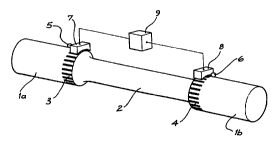
Fig. 1 shows grating elements 3 and 4 attached to torque input members 1 a and
1 b of
so the shaft at either end of a torsionally compliant coupling in the form of
torsion bar 2.
Grating elements 3 and 4 comprise surfaces composed of alternating regions of
high and
low reflectivity. Electromagnetic radiation (EMR) sources 5 and 6 are disposed
to
CA 02307038 2000-02-07
PCT/AU98/00645
Received 24 June 1999
11
illuminate the surfaces. Arrays 7 and 8 of EMR sensitive detectors receive
incident EMR
reflected from the surfaces and the patterns thus generated on arrays 7 and 8
are
processed by processor 9.
s
Fig. 2 shows a cross section of a torque transducer according to a first
embodiment of
the present invention, using the principles shown in Fig. 1. Cylindrical
grating elements 3
and 4, comprising surfaces composed of alternating high and low reflectivity,
are
attached to torque input members 1 a and 1 b which are connected to either end
of the
to torsion bar 2. In other (not shown) embodiments either (or both) grating
elements may be
integral with their respective torque input members. The assembly is enclosed
in
housing 10 and supported by bearings 11 and 12. EMR sources 5 and 6 are
disposed to
illuminate the surfaces. Arrays 7 and 8 of detectors receive incident EMR from
the
surfaces and the patterns thus generated on the arrays are processed by a
processor 9
is to provide a measurement of torque. When torque is applied between torque
input
members 1 a and 1 b torsion bar 2 angularly deflects, resulting in a
displacement of one
pattern with respect to the other. Failsafe mechanism 15 limits the maximum
torque
carried by the torsion bar 2 by providing a limit to the amount of angular
deflection of
torque input member 1 a with respect to torque input member 1 b. Such a
failsafe
2o mechanism is well known in the art of power steering.
Fig. 3 shows another embodiment. Cylindrical grating elements 17 and 18, each
comprising a continuous cylindrical surface composed of substantially axially
aligned
regions of alternating high and low reflectivity, are attached to torque input
members 1 a
2s and 1 b respectively which are in turn connected to either end of the
torsion bar 2.
Grating elements 17 and 18 are arranged such that they are adjacent. EMR
source 19 is
arranged to illuminate both surfaces, and the array 20 of detectors receives
incident
EMR from both surfaces and the pattern thus generated on the array is
processed by the
processor 9 to provide a measurement of torque.
Figs. 4, 5 and 6 shows a second embodiment of the present invention.
Cylindrical grating
AMENDED SHEET (Article 341 (IPEA/AUl
CA 02307038 2000-02-07
WO 99/09385 PCT/AU98/00645
12
elements 21 and 22 are attached to torque input members 1 a and 1 b, connected
to
either end of the torsion bar 2. The outer cylindrical surfaces of grating
elements 21 and
22 are discontinuous and are formed in part by substantially axially aligned,
radially
s protruding castellations 13 and 14 respectively. The regions of high
reflectivity
correspond to the areas of maximum radius of the castellations with respect to
their
mutual central axis 16, that is outer peripheral areas 13a and 14a
respectively, and may
be smoothly machined, moulded or sintered, or surtace treated with paint or
material
deposition to impart the required high reflectivity. The regions of low
reflectivity are
to angularly aligned with the discontinuous gap areas of the outer cylindrical
surfaces of
grating elements 21 and 22, namely areas 13b and 14b respectively and, in the
embodiment shown here, are substantially non-reflective due to the presence of
fully-
radially-extending (ie. full depth) cavities 13c and 14c between adjacent
castellations 13
and 14 on each grating element 21 and 22 respectively. In other embodiments
(not
is shown) the cavities may be alternatively truncated at a lesser radius than
the
aforementioned maximum radius, such resulting surface of lesser radius ideally
being
machined, moulded or sintered, or surface treated with paint or material
deposition to
impart low reflectivity. Grating elements 21 and 22 are interdigitally
arranged as shown
in Fig. 5. This assembly is enclosed in housing 10 and supported by bearings
11 and 12.
2o An EMR source 19 is arranged to illuminate the surfaces, and array 20 of
detectors
receives incident EMR reflected from the regions of high reflectivity 13a and
14a on the
outer cylindrical surfaces of grating elements 21 and 22 respectively. The
pattern thus
generated on array 19, comprising therefore interdigitally disposed subpattems
generated by incident EMR reflected from regions 13a and 14a respectively, is
2s processed by the processor 9 to provide a measurement of torque.
Failsafe mechanism 15, shown in cross section in Fig. 7, limits the maximum
torque
carried by torsion bar 2 by providing a maximum limit to its angular
deflection. Referring
back to Fig. 2, element 51 is a feature of torque input member 1 a and element
52 is a
3o feature of torque input member 1 b, and interact to limit the maximum
angular deflection
of torsion bar 2. When the torque applied to torsion bar 2 reaches a
predetermined
CA 02307038 2000-02-07
WO 99/09385 PCT/AU98/00645
13
maximum value elements 51 and 52 contact rotationally, providing an alternate
torsional
load path to torsion bar 2.
s Figs. 8 and 9 show a third embodiment of the present invention. Cylindrical
grating
elements 25 and 26, each comprising a substantially smooth cylindrical surface
with
alternating regions of high and low reflectivity, are respectively attached to
torque input
members 1 a and 1 b, which in turn are connected to either end of torsion bar
2. This
assembly is enclosed in housing 10 and supported by bearings 11 and 12. A
metallised
to coating, or other shiny or light coloured material or surface treatment,
provides
substantially axially aligned regions of high reflectivity 25a and 26a. A
substantially
transparent, roughened or dark coloured material or surface treatment provides
the
interspaced regions of low reflectivity 25b and 26b. EMR source 19 is arranged
to
illuminate both surfaces, and the array 20 of detectors receives incident EMR
from the
is surfaces and the pattern thus generated on the array is processed by
processor 9 to
provide a measurement of torque. Failsafe mechanism 15, shown in cross section
in
Fig. 7, limits the maximum torque carried by the torsion bar 2 as described
earlier.
Figs. 10 and 11 show a fourth embodiment of the present invention. Grating
elements 29
2o and 30, again respectively attached to torque input members 1 a and 1 b,
incorporate
continuous, radially disposed surfaces 23 and 24. These radially disposed
surfaces are
arranged perpendicular to, and have a mutual central axis collinear with, axis
of rotation
16. Each surface comprises substantially radially disposed alternating regions
of high
and low reflectivity 27 and 28 respectively. Grating elements 29 and 30 are
surrounded
2s by housing 10 and the assembly carried in bearings 11 and 12. EMR sources
31 and 32
are disposed to illuminate the surfaces. Arrays 33 and 34 of detectors receive
incident
EMR from the surfaces and the patterns thus generated on the arrays are
processed by
processor 9. When torque is applied between torque input members 1 a and 1 b,
torsion
bar 2 angularly deflects, resulting in a displacement of one pattern with
respect to the
30 other. Failsafe mechanism 15, shown in cross section in Fig. 7, limits the
maximum
torque carried by the torsion bar 2 as described earlier.
CA 02307038 2000-02-07
WO 99/09385 PCT/AU98/00645
14
Figs. 12, 13 and 14 show a fifth embodiment of the present invention. Grating
elements
35 and 36 comprise radially disposed surfaces arranged perpendicular to, and
having a
mutual central axis collinear with, axis of rotation 16. The surfaces are
formed by axially
s protruding castellations 37 and 38 respectively, the regions of high
reflectivity provided
by the areas of maximum axial protrusion 37a and 38a of castellations 37 and
38, and
the regions of low reflectivity angularly aligned with the discontinuous gap
areas 37b and
38b between the castellations. The root areas 37c and sides 37d of
castellations 37, and
also the sides 38d of castellations 38, have lesser axial protrusion than
regions 37a and
l0 38a and are machined, moulded or sintered, or surface treated with paint or
material
deposition to impart low reflectivity. The grating elements are interdigitally
meshed as
shown in Fig. 14. This assembly is enclosed in housing 10 and supported by
bearings
11 and 12. An EMR source 39 is arranged to illuminate the surfaces, and an
array 40 of
detectors receives incident EMR reflected from the surfaces. The pattern thus
generated
is on array 19, therefore comprising interdigitally disposed subpattems
generated by
incident EMR reflected from regions 37a and 38a respectively, is processed by
the
processor 9 to provide a measurement of torque. Failsafe mechanism 15, shown
in cross
section in Fig. 7, limits the maximum torque carried by the torsion bar 2 as
described
earlier.
Figs. 15 and 16 show a sixth embodiment of the present invention. Grating
elements 41
and 42, again attached to torque input members 1 a and 1 b respectively,
incorporate
continuous radially disposed surfaces 43 and 44. These radially disposed
surfaces are
substantially coplanar and concentric with respect to axis of rotation 16.
Each surface is
2s smooth and incorporates substantially radially disposed alternating regions
of high and
low reflectivity. A metallised coating, or other shiny or light coloured
material or surface
treatment, provides the regions of high reflectivity 41 a and 42a. A
substantially
transparent, roughened or dark coloured material or surface treatment provides
the
regions of low reflectivity 41 b and 42b. EMR source 39, array 40 of detectors
and
so processor 9 are used to generate a measurement of torque.
CA 02307038 2000-02-07
WO 99/09385 PCT/AU98/00645
Figs. 17 and 18 show an alternative version of the second embodiment of the
present
invention (refer back to Figs. 4, 5 and 6). Two grating elements 44 and 45 are
adjacent
and comprise radially extending intermeshing castellations 44a and 45a which
provide a
measurement of torque similar to that described in reference to grating
elements 21 and
22 of the second embodiment. The clearance provided between castellations 44a
and
45a provides a rotational lost motion connection between the first and second
torque
input members and hence limits the maximum angular deflection of torsion bar
2. When
the torque applied between torque input members 1 a and 1 b reaches a
predetermined
to maximum value in either direction, castellations 44a and 45a contact,
providing an
alternate torsional load path to the torsion bar 2, thus allowing elimination
of failsafe
mechanism 15 by providing the same function.
Fig. 19 shows an alternative version of the third embodiment of the present
invention
is {refer back to Figs. 8 and 9), however it should be noted that this same
concept could be
readily applied to any of the embodiments disclosed in this specification. Two
grating
elements 46 and 47 comprise cylindrical surfaces composed of alternating
regions of
high and low reflectivity, similar to those as shown in Figs. 8 and 9. In
addition to these
regions, at least one additional "home mark" region 48 (or, alternatively not
shown, an
2o axially lengthened existing region) of high or low reflectivity is added to
one of the
surfaces at a predetermined angular position. EMR source 19 is arranged to
illuminate
both surfaces, and array 20 of detectors receives incident EMR from the
surfaces and
the patterns thus generated on the array is processed by the processor 9 to
provide a
measurement of torque and also absolute angular position of the torque input
member to
is which the relevant grating element is attached to or integral with.
Figs. 20 - 25 show typical patterns produced by incident EMR on the various
array
combinations according to the present invention. Note that, for illustration
in all these
figures, the black-rendered portions correspond to highly illuminated portions
of the
3o patterns while the non-rendered (ie. white) portions correspond to low (or
essentially
non) illuminated portions of the patterns.
CA 02307038 2000-02-07
WO 99/09385 PCT/AU98/00645
16
Fig. 20a and 20b show typical patterns produced by incident EMR on first and
second
arrays according to the first embodiment of the present invention. In Fig. 20a
the arrays
are two dimensional arrays, and for example each incorporate a Texas
Instruments
s TC277 Black & White CCD Image Sensor with 699 x 288 pixels and an active
window
size of approximately 8 mm x 6 mm. The methods by which the patterns are
processed
are generally well known in the art of image analysis, and some of these
methods used
are described in "Vision Chips: Implementing Vision Algorithms with Analog
VLSI
Circuits", by Christof Koch and Hua Li, IEEE Computer Society Press, ISBN 0-
8186-
io 6492-4. In order to improve edge delineation, it is seen in Fig. 20a that
the arrays are
mounted at a small angle 't' (typically less than 15 deg.) with respect to the
respective
patterns. This misalignment produces more information relating to the edge
position
since the pattern no longer "beats" with the pixel alignment of the array and
regression
techniques are therefore more accurate due to an increased amount of data.
Dimension
is 'x', being the average relative displacement between the patterns on the
two arrays,
relates directly to the relative angular displacement of the two grating
elements and
hence to shaft torque. In Fig. 20b the arrays are one dimensional arrays, and
for
example each incorporate a Texas Instruments TSL1410 Black & White Linear
Array
chip with 128 pixels and an active window length of approximately 8 mm.
Dimension 'x' is
2o measured similarly however, without the benefits of improved edge
delineation provided
by the above mentioned two dimensional arrays. In the case of all embodiments
of the
arrays described in this specification, a lens (for example spherical,
aspherical, or
Fresnel) or a fibre optic array light guide is incorporated in front of the
EMR sensitive
detectors in order that the incident EMR is focussed as a sharp pattern and
any spurious
2s cross-reflection is minimised.
Fig. 21 a and 21 b show typical patterns produced by incident EMR on a single
array
according to the second embodiment of the present invention. In Fig. 21 a the
array is a
two dimensional array as described above. Dimension '(x-y)/2', being the
average
so relative displacement between the interdigitally disposed wide and narrow
subpattems
CA 02307038 2000-02-07
WO 99/09385 PCT/AU98/00645
17
50 and 51 respectively, relates directly to the relative angular displacement
of the two
grating elements and hence to shaft torque. Fig. 21 b shows the pattern in the
case of a
one dimensional array as described above. Dimension '(x-y)/2' can be measured
similarly and the appropriate recognition and processing aspects are well
described in
International Patent Application PCT/GB95/02017.
Fig. 22 shows a typical pattern produced by incident EMR on a single two
dimensional
array according to the third embodiment of the present invention. Again
dimension '(x-
to y)/2', being the average relative displacement between the two laterally
separated
subpatterns 52 and 53, relates directly to the relative angular displacement
of the two
grating elements and hence to shaft torque.
Figs. 23a and 23b show typical patterns produced by incident EMR on first and
second
is arrays according to the fourth embodiment of the present invention. Of
course the
patterns in this case are substantially radially disposed rather than parallel
as in the case
of the first embodiment shown in Figs. 20a and 20b, still the basic
methodology for
determination of dimension 'x', and hence shaft torque, is similar for both
cases of the
arrays being two dimensional or one dimensional.
Fig. 24a and 24b show typical patterns produced by incident EMR on a single
array
according to the fifth embodiment of the present invention. Apart from the
wide and
narrow interdigitally disposed subpattems 54 and 55 being substantially
radially
disposed, rather than parallel as in the case of the second embodiment shown
in Figs.
2s 21 a and 21 b, the basic methodology for determination of dimension '(x-
y)/2', and hence
shaft torque, is similar for both cases of two dimensional and one dimensional
arrays.
Fig. 25 shows a typical pattern produced by incident EMR on a single two
dimensional
array according to the sixth embodiment of the present invention. Dimension
'(x-y)/2',
3o being the average relative displacement between the two radially separated
subpatterns
CA 02307038 2000-02-07
WO 99/09385 PCT/AU98/00645
18
56 and 57, relates directly to the relative angular displacement of the two
grating
elements and hence to shaft torque.
For all six embodiments described above the pattern migrates across the
limited width
one dimensional or two dimensional arrays) as the shaft rotates, quite
independent of
shaft torque. Again, using techniques well known in the discipline of pattern
recognition,
the rate of pattern migration and the total displacement of the pattern can be
calculated
providing a measure of the angular velocity and relative angular position of
the torque
to input members. A "home mark" on the surface of one of the grating elements,
as
described in reference to Fig. 19, can be used as an absolute angular position
reference.
The intervening marks can be counted from this home mark position by the
processor to
provide a measurement of absolute angular position of the torque input member
to which
the relevant grating element is attached to or integral with.
is
Figs. 26a-a show details of the regions of high and low reflectivity on the
cylindrical
surfaces of grating elements 58 and 59, according to another alternative
version of the
third embodiment of the present invention (refer back to Figs. 8 and 9). These
regions
are arranged in the form of a succession of 120 individual non-overlapping
binary bar
2o codes 60a-g.... and 61 a-g.... on the periphery of each of the grating
elements 58 and 59
respectively. These 120 bar codes are disposed at a uniform 3 degree angular
spacing
on the periphery of each grating element.
Fig 27 shows details of bar code 60a on grating element 58, in order to better
describe
2s the bar code format. Each bar code comprises 9 bars in total: one "start"
bar 62a, seven
"angle position" bars 62b-h, and one "stop" bar 62i. In this embodiment start
bar 62a and
stop bar 62i are always regions of high reflectivity whereas interposed angle
position
bars are either regions of high or low reflectivity depending on the binary
value of the
angle position value to be encrypted. For example bar code 60a comprises
regions of
3o high reflectivity in the form of bars 62c, 62d, and 62f and regions of low
reflectivity in the
form of bars 62b, 62e, 62g and 62h. Bar code 60a therefore has a binary value
of
CA 02307038 2000-02-07
WO 99/09385 PCT/AU98/00645
19
0110100 or an angle position value of 52 (base 10). The use of seven angle
position
bars enables theoretically the encryption of up to 128 discrete angle position
values
which is necessary to encompass and individually identify each of the 120 bar
codes on
each grating element.
Fig. 26a shows the position of grating elements 58 and 59 when zero torque is
applied to
torque input members 1 a and 1 b (refer back to Fig. 8). It is seen that bar
codes 60a and
61 a, both corresponding to angle position value of 52 on grating elements 58
and 59
to respectively, are mutually aligned for this zero torque condition. The same
is true for all
other 119 bar code pairs 60b and 61 b, 60c and 61 c, etc. The method of
manufacturing
of such successions of bar codes on grating elements, and accurately mutually
aligning
them at the zero torque condition, is described in a co-pending Australian
Provisional
Patent Application entitled "Method For Manufacture of Optical Torque
Transducers".
is
Figs. 26b-a show successive relative angular displacements of grating elements
58 and
59 as an increasing anticlockwise torque is applied to torque input member 1 b
with
respect to torque input member 1 a. The viewing window of two-dimensional
array 20 is
also shown superimposed as dotted lines in these diagrams. Note that this
viewing
2o window is chosen to be sufficiently large to always capture at least one
complete bar
code from each of the two grating elements, irrespective of the relative
angular
displacement of the two grating elements (as a function of input torque) and
the absolute
rotation angle of the grating elements over their 360 degree possible range
(as a function
of steering angle). In order to reduce total silicon usage (and hence cost),
two separate
2s one-dimensional (ie. linear) arrays or smaller elongated two-dimensional
arrays 63 and
64 could be used instead of the larger two dimensional array 20. In certain
VLSI vision
chip configurations, array 20 or arrays 63 and 64 may be embedded in, attached
to, or
integrated as part of, the microprocessor chip used to carry out the necessary
processing, that is processor 9.
Array 20 (or arrays 63 and 64) receive incident EMR reflected from the regions
of high
CA 02307038 2000-02-07
WO 99/09385 PCT/AU98/00645
reflectivity on the surfaces of grating elements 58 and 59 which are
instantaneously in
the array's (or arrays') viewing window. In the example shown in Figs. 26b-d,
array 20 (or
arrays 63 and 64) receive incident EMR from bar codes 60c and 61 c and
processor 9 is
therefore able to derive relative displacement distance 'd' of the peripheries
of respective
grating elements 58 and 59 and hence a measure of input torque.
Figs. 28a and 28b show the position of grating elements 58 and 59 for two
successive
relative positions, according to another alternative version of the third
embodiment of the
io present invention (refer back to Figs. 8 and 9). Zero torque is applied to
torque input
members 1 a and 1 b (refer back to Fig. 8) in the case of Fig. 28a. Fig. 28b
shows the
situation of a torque applied to torque input members 1 a and 1 b producing a
relative
displacement 'd' of the peripheries of respective grating elements 58 and 59.
These
regions are arranged in the form of a succession of 512 individual 9 bit
binary bar codes
is 70a-i... and 71 a-i... on the periphery of each of the grating elements 58
and 59
respectively. An example of one combination of such bar codes is described as
an
Ouroborean ring in "Game, Set and Math" by Ian Stewart, Penguin Books, 1989.
These
512 bar codes overlap and are disposed at a circumferential spacing equal to
an integer
multiple of the width of one of the bars 72 on the periphery of each grating
element. In
2o the embodiment shown, this multiple is unity, and the spacing is equal to
the width of one
of the bars. The viewing window of two-dimensional array 20 is also shown
superimposed as dotted lines in these diagrams. In order to reduce total
silicon usage
(and hence cost), two separate one-dimensional (ie. linear) arrays or smaller
elongated
two-dimensional arrays 63 and 64 could be used instead of the larger two
dimensional
2s array 20. In certain VLSI vision chip configurations, array 20 or arrays 63
and 64 may be
embedded in, attached to, or integrated as part of, the microprocessor chip
used to carry
out the necessary processing, that is processor 9. Array 20 (or arrays 63 and
64)
receive incident EMR reflected from the regions of high reflectivity on the
surfaces of
grating elements 58 and 59 which are instantaneously in the array's (or
arrays') viewing
3o window. As shown in Fig 28b, array 20 (or arrays 63 and G4) receive
incident EMR from
CA 02307038 2000-02-07
WO 99/09385 PCT/AZJ98/00645
21
bar codes 80a-i and 81 a-i and processor 9 is therefore able to derive
relative
displacement distance 'd' of the peripheries of respective grating elements 58
and 59
and hence a measure of input torque. In the situation shown in Fig 28b, the
grating
s elements 58 and 59 have also net-rotated from the position shown in Fig.
28a, causing
the array 20 (or arrays 63 and 64) to receive incident EMR from bar codes 80a-
i and
81 a-i, which are displaced from (but still overlap) bar codes 70a-i and 71 a-
i. Note that
the viewing window is chosen to be sufficiently large to always capture at
least one
complete bar code from each of the two grating elements, irrespective of the
relative
to angular displacement of the two grating elements (as a function of input
torque) and the
absolute rotation angle of the grating elements over their 360 degree possible
range (as
a function of steering angle).
Fig 29 shows details of bar code 70a-i on grating element 58, in order to
better describe
is the bar code format. Each bar code comprises 9 bars in total. In this
embodiment the
bars are either regions of high or low reflectivity depending on the binary
value of the
angle position value to be encrypted. For the example shown, bar code 70a-i
comprises
regions of high reflectivity in the form of bars 70c, 70e and 70g and regions
of low
reflectivity in the form of bars 70a, 70b, 70d, 70f, 70h and 70i. Bar code 70a-
i therefore
2o has a binary value of 001010100 or an angle position value of 84 (base 10).
The use of
nine angle position bars enables theoretically the encryption of up to 512
discrete angle
position values which is necessary to encompass and individually identify each
of the
512 bar codes on each grating element.
2s Most importantly however, in both of the bar code embodiments described in
Figs. 26-29,
processor 9 is now also programmed to decode the angle position values of all
complete
binary bar codes which are in the viewing window at any one time. For example
in the
case of the bar code embodiment shown in Figs. 26 and 27, bar codes 60c and 61
c both
correspond to angle position value 54. The use of bar codes in general has two
3o significant advantages in the case of the present invention.
CA 02307038 2000-02-07
WO 99/09385 PCT/AU98/00645
22
Firstly, for still larger relative displacements of grating element 58 with
respect to grating
element 59, the problem of aliasing is avoided. This is readily demonstrated
in the case
of the bar code embodiment shown in Figs. 26 and 27. In Fig. 26e bar code 60b
(angle
position value 53) on grating element 58 has displaced a sufficient distance
to the right
that it now actually lies between bar codes 61 c and 61 d (angle position
values 54 and 55
respectively) on grating element 59. However by recognising that the angle
position
value of bar code 60b is 53, and that therefore its relative position at the
zero torque
condition is adjacent to bar code 61 b on grating element 59, the correct
relative
io displacement of the grating elements can be calculated as:
d = a + (54 - 53)*3*r*pi/180 = a + 3*r*pi/180 (deg)
where r is the radius of the grating element.
is
Without the use of bar codes, aliasing would have occurred for a much smaller
relative
displacement of the two grating elements, namely when bar code 60b became
adjacent
to bar code 61 c. By arranging the regions of high and low reflectivity in the
form of
successive binary bar codes, relative angular displacements of grating
elements 58 and
20 59 can be correctly measured for substantial deviations from the zero
torque condition,
and independent of the actual spacing of the regions of high and low
reflectivity.
Secondly, use of bar codes enables measurement of the absolute angular
position of
either of the two torque input members 1 a and 1 b through a range of 360 deg,
that is +/-
2s 180 deg from some known absolute position. This is achieved without the
need for any
counting process to be carried out in processor 9 (as in the case of the
previous
alternative version of the third embodiment of the present invention shown in
Fig.l9).
If the maximum relative angular displacement of the grating elements is
externally limited
so in some manner, for example via the use of a failsafe mechanism as earlier
described,
CA 02307038 2000-02-07
WO 99/09385 PCT/AU98/00645
23
aliasing may not be a problem and in this case successive bar codes may be
employed
on only one of the two grating elements. This will still provide sufficient
information to
provide a measure of absolute angular position over the above mentioned +/-180
deg
range.
It should be noted that the use of bar codes can be similarly applied to other
cylindrical
reflective grating element configurations, for example that described in
reference to the
first embodiment of the present invention (refer to Figs. 1 and 2). Also bar
codes can be
~o applied to radially disposed reflective grating element configurations, for
example those
described in reference to the fourth {Figs. 10 and 11 ) and sixth (Figs. 15
and 16)
embodiments of the present invention.
Also, it should be noted that bar codes can take many forms apart form the non-
is overlapping (discrete) barcode arrangement shown in Figs. 26a-a and Fig.
27, and the
overlapping (Ouroborean) barcode arrangement shown in Figs. 28a-b and Fig 29.
For
example a classic Manchester barcode arrangement {as used on computer hard
disk
drives) or a constantly pitched "thick-thin line" barcode arrangement (as used
on many
household consumer products) would also be suitable for application to
cylindrically and
2o radially disposed grating elements.
It should also be noted that the succession of bar codes could have reverse
reflectivity
compared to the embodiment described, that is low reflectivity regions imposed
over a
high reflectivity background, rather than the other way around as described.
Also in the
2s present specification "high reflectivity" and "low reflectivity" is broadly
defined in
reference to the particular EMR source selected. For example, if a red light
EMR source
was used, the regions of high and low reflectivity of the surfaces of the
reflective gratings
may consist of regions which are painted (or otherwise coloured by some means)
with a
red and blue surface coating respectively.
Lastly it should be noted that the surfaces of the reflective grating elements
may have
CA 02307038 2000-02-07
WO 99/09385 PCT/AU98/00645
24
forms other than the cylindrical or disc-like forms described by way of the
above
mentioned embodiments. specifically the surfaces of the grating elements can
have
other three-dimensional axi-symmetric forms about the axis of the shaft, for
example
conical, elliptoidal , or paraboloidal forms. Any arbitrary axi-symmetric form
of surface
can potentially be used providing that the deviation of the distance between
the surface
and the respective array (receiving incident EMR from this surface) is
sufficiently small in
magnitude, that the afore mentioned lens or fibre optic light guide system can
maintain a
satisfactory level of focus of the patterns (or subpattems on the array).
io
It will be appreciated by those skilled in the art that numerous variations
and
modifications may be made to the invention without departing from the spirit
and scope
of the invention.