Note: Descriptions are shown in the official language in which they were submitted.
CA 02307116 2000-04-19
WO 99/23686 PCT/CA98/00999
_1-
Title: A METHOD OF OPERATING A MASS SPECTROMETER
INCLUDING A LOW LEVEL RESOLVING DC INPUT TO IMPROVE
SIGNAL TO NOISE RATIO
FIELD OF THE INVENTION
This invention relates to a mass analyzer. More
particularly, it relates to a rod type mass analyzer or spectrometer, which is
simple and inexpensive, and which includes both applied RF and DC
voltages.
BACKGROUND OF THE INVENTION
Quadrupole mass spectrometers have proven to be general
purpose mass analyzers. These devices are four rod structures and, when
operated in a resolving mode, the rods are usually about 20 cm in length
and require extreme mechanical precision in terms of fabrication and
alignment. When operated in resolving mode quadrupole mass
spectrometers have both RF and DC voltages applied to them, and are
pumped to a relatively high vacuum (e.g. 10-5 Torr). Values of these
voltages vary with the frequency and mass range of operation, but can be on
the order of 1600 volts (peak-to-peak) RF for operation at 1 MHz and 272
volts DC for a rod array inscribed radius ro of 0.415 cm and a mass range of
600 Daltons. The high degrees of mechanical and electrical sophistication
required means that the costs of these mass spectrometers are high.
There has accordingly been a long standing need for a
simpler, less expensive mass spectrometer. While costs have been reduced,
quadrupole and other rod mass spectrometers (e.g. octopoles and hexapoles)
have continued to remain extremely expensive and to require very close
tolerances and high vacuum pumping equipment, as well as costly power
supplies.
Attempts have been made to simplify the design and
operation of quadrupole mass spectrometers, and one proposal is found in
U.S. Patent 4,090,075. This patent teaches that a quadrupole mass
spectrometer can provide mass resolution in the absence of applied
resolving DC voltages. This so called RF-only mode of operation has
SUBSTITUTE SHEET (RULE 26)
CA 02307116 2000-04-19
- WO 99/23686 PCT/CA98/00999
-2-
several advantages over conventional RF/DC operational modes.
Conventional RF/DC quadrupole rod mass spectrometers supply mass
resolution based on the intrinsic stability or instability of given ions
within
the rod structure in the combination of the time varying RF and the time
independent DC fields. In contrast to the more common RF/DC
quadrupole mass analyzers, mass resolution for an RF-only instrument is
thought to occur when ions that are only marginally stable with a particular
applied RF voltage gain excess axial kinetic energy in the exit fringing field
of the rod structure. A large part of the phenomena leading to mass
resolution of an RF-only mass analyzer occurs at the exit of the rod array, so
the length limitations characteristic of RF/DC resolving quadrupoles no
longer apply and mechanical tolerances for rod roundness and straightness
are considerably relaxed. Finally, there is no need for a high precision high
voltage DC power supply in the RF-only mode of operation. Taken together
the inherent advantages of RF-only operation suggest the opportunity for a
much smaller and less costly mass analyzer than conventional RF/DC
quadrupoles. Although the potential of such a device is significant,
problems arise, such as sample dependent background from high velocity
ions and clusters. The current invention describes a method for
elimination of these background species.
Another proposal is found in US patent 4,189,640, which
describes a method for background reduction for RF-only quadrupole mass
analyzers. This invention teaches that a centrally located attractively biased
disk of the appropriate size located after the analyzing quadrupole reduces
high velocity and higher mass species. However, in practice this also
reduces analyte ion intensity offsetting much of the expected gains in the
signal-to-noise ratio.
SUMMARY OF THE INVENTION
In accordance with the present invention, there is provided
a method of operating a mass spectrometer having first and second rod sets,
the second rod set being downstream from the first rod set and at an outlet
of the spectrometer, the method comprising: directing ions into the first rod
SUBSTITUTE SHEET (RULE 26)
CA 02307116 2000-04-19 .= == = " ~' =~
. .. . . . = =
.. .. . .. ~ . . . . .. =
. . . . . . . . ... ...
~ . . . ... . . . ~ ~ ~
. . .
= ' ~..~ .. ... .. == =
. =
-3-
provided a method of operating a mass spectrometer having first and
second rod sets, the second rod set being downstream from the first rod set
and at an outlet of the spectrometer, the method comprising: directing ions
into the first rod set; applying an RF voltage to the first rod set and an RF
voltage to the second rod set; and applying a low level resolving DC voltage
to the second rod set sufficient to reduce a continuum background ion
signal, thereby to increase the signal-to-noise ratio of the spectrometer;
energy filtering the ions leaving the second rod set, before detecting said
ions for analysis, whereby ions with a q value of substantially 0.907 gain
sufficient energy to pass through the energy filtering for detection; and
detecting, for analysis, ions leaving the second rod set.
As noted above, the method is based on the so-called RF-
only mode of operation, and tile Rtr'' voliage applied to the second rod set
can be scanned, thereby to obtain an m/z spectrum.
In one mode of operation, the DC voltage is maintained at a
constant ratio with respect to the RF voltage, so as to scan the DC voltage
with the mass of ions detected. Alternatively, a constant DC voltage is
applied, and the DC and RF voltages are then selected so as to permit a
desired analyte ion to pass through the spectrometer for detection, but such
as to cause heavier, background ions to be substantially rejected, whereby
the background ions are substantially not detected.
In conventional spectrometer operation at the tip of the a-q
diagram, it is necessary to control the RF and DC levels accurately. In
contrast, with the present invention, as the DC level is used for entirely
different purposes, the tolerance on the DC to RF ratio can be in a much
larger band and preferably is kept within a range of plus or minus 15%.
Where a fixed DC level is used, the DC voltage is preferably
in the range 0-15.5 volts. It may alternatively lie between 0 volts DC and
40% of the DC normally required for the rod set to operate at the tip of the a-
q stability diagram for the rod set.
~
''~
. - ~~ .
+ - ' CA 02307116 2000-04-19.. .= = == =' "
. . a
w= .i ~ = ~ ~ ~= = i = = = = .
a = = = = ==. = = = a = === =a=
a = =
a a = = = === =.= =. =
a ~ a= ==
-3A-
Advantageously, the method is carried out with a mass
spectrometer including at least one additiorral, upstream rod set, wherein
the method comprises applying an.RF voltage to the upstream rod set and a
DC offset voltage to all the rods of the upstream rod set. The second rod set
can comprise an analysis rod set comprising a quadrupole rod set, wherein
the DC voltage is applied between opposite pairs of rods, whereby one
opposite pair of rods is at one potential and the other opposite pair of rods
is
at another potential.
r)
~\~ !'
CA 02307116 2000-04-19
WO 99/23686 PCT/CA98/00999
-4-
BRIEF DESCRIPTION OF THE DRAWINGS
For a better understanding of the present invention, and to
show more clearly how it may be carried into effect, reference will now be
made, by way of example, to the accompanying drawings, in which:
Figure 1 is a plot of the well-known a-q operating diagram
for quadrupole mass spectrometer;
Figure 2a is a plot showing the distribution of an ion axially
energies produced by a typical RF-only quadrupole set of rods;
Figure 2b is a plot similar to Figure 2a, but showing the ion
energy distribution after the ions have passed through the fringing fields of
the exit end of the RF-only quadrupole rods;
Figure 3 is a diagrammatic view showing an RF-only mass
spectrometer configuration;
Figures 4a, 4b and 4c are graphs of intensity against amu,
showing the effect of increasing the DC voltage applied to the rods;
Figure 5 is a graph of intensity against amu, showing the
effect of progressively increasing the DC voltage; and
Figure 6 is a graph of DC voltage against RF voltage,
showing characteristics of an analyte and a background ion.
DETAILED DESCRIPTION OF THE PREFERRED EMBODIMENT
Referring to Figure 1 which shows the well known
operating diagram for a quadrupole mass spectrometer, the a parameter is
plotted on the vertical axis and the q parameter on the horizontal axis.
Here, as is well known:
a=8eU/(mcw2ro2)
q=4eV / (mw2ro2)
where U is the amplitude of the DC voltage applied to the rods , V is the RF
voltage applied to the rods, e is the charge on the ion, m is its mass, w is
the
RF frequency, and ro is the inscribed radius of the rod set.
In the Figure 1 operating diagram ions within the shaded
area are stable provided they are above the operating line. In conventional
SUBSTITUTE SHEET (RULE 26)
CA 02307116 2000-04-19
WO 99/23686 PCT/CA98/00999
-5-
RF/DC operation the operating line is made to lie near the tip or apex 14 of
the operating diagram. The operating line is indicated at 12 and shows
operation at a constant DC/RF ratio. The theoretical resolution of such a
device is given by the width Ll of the peak above the operating line divided
by the width L2 of the base of the operating diagram. This requires, as
mentioned, substantial RF and DC voltages be applied to the rods. In theory
very high mass resolution is possible with RF/DC quadrupoles operating
near the tip of the stability diagram, but this requires extremely high
mechanical precision of the dimensions of the rod structure and high
precision control of the RF voltage, the DC voltage, and the RF/DC ratio.
Degradation of any of these high tolerances directly affects the mass
resolving capabilities of the device and can lead to poor analytical
performance.
Operation of a quadrupole in RF-only mode (that is
without DC) is known and effectively results in the operating line in Figure
1 being along the horizontal axis. Thus, the device acts essentially as an ion
pipe and transmits ions with a very wide range of mass to charge ratio
(m/z). Ions with q<-0.907 are stable. Ions with a q value above -0.907
become radially unstable, hit the rods, and are not transmitted.
Mass resolution of an RF-only quadrupole mass
spectrometer is thought to occur when ions with q of - 0.907 gain significant
radial amplitude. In the exit fringing field of the device these ions, with
large radial trajectories, are subjected to intense axial fields, and thus,
these
ions emerge with large exit axial kinetic energies. The fact that the
phenomenon responsible for mass resolution of an RF-only quadrupole
occurs at the exit of the device rather than throughout the length of the rod
structure means that mechanical tolerances are significantly relaxed with
respect to those of a conventional RF/DC quadrupole mass spectrometer.
The ions near q~0.907 that have higher exit axial kinetic
energies than the lower q ions can be detected preferentially by virtue of
this
excess axial kinetic energy. In practice energy filtering is accomplished by
the placement of a retarding grid either at the exit of the quadrupole or
further downstream. Particles are detected when (mvn 2) /2>eVr where m is
SUBSTITUTE SHEET (RULE 26)
CA 02307116 2000-04-19
- WO 99/23686 PCT/CA98/00999
-6-
the mass of the ion, e is the charge on the ion, vn is the ion velocity normal
to the grid plane, and V, is the retarding potential applied to the grid. Ion
optic elements other than a planar grid can also be employed with varying
efficiencies.
The energy considerations are illustrated in Figures 2A and
2B. Figure 2A shows the standard axial energy distribution 16 of ions
introduced into an RF-only quadrupole rod set, plotted against the number
of ions. The width of the energy distribution curve 16 will depend on the a
number of factors such as the nature of the ion source and the ion optics in
front of the quadrupole rods.
Figure 2B shows the curve 16 from Figure 2A and also the
curve representing the distribution of axial energies 18 of ions whose q is
about 0.9 and which therefore have received additional axial energy in the
exit fringing field at the end of the RF-only quadrupole rods. If there is
sufficient separation between the two curves energy filtering using a grid
can be made very efficient, and only the ions that have gained axial kinetic
energy in the exit fringing field are detected. A mass spectrum can be
obtained in this way, by scanning the RF voltage applied to the quadrupole
rods to bring the q of ions of various masses to near 0.907, at which time the
large radial energies which they acquire yield increase axial energies, so
these ions can be separated.
A drawback associated with this energy filtering technique
is that there can be a significant high energy tail in the energy distribution
16 of ions entering the quadrupole rods. These high energy ions can
originate in the ion source itself, the ion optics used to transport the ions
from the source to the quadrupole rods, or from physical and chemical
changes (such as metastable decomposition or collision-induced
fragmentation) of the ion from the ion source to the quadrupole rods. This
results in significant overlap of the curves 16 and 18 represented in Figure
2B and thus the appearance of a continuum background signal upon which
rides the resolved peaks from the ions with a q near 0.907. Higher mass
ions with q<0.9 but with some radial excitation can also contribute to
background ion current. The combination of these effects can lead to poor
SUBSTITUTE SHEET (RULE 26)
CA 02307116 2000-04-19
WO 99/23686 PCT/CA98/00999
-7-
signal-to-noise and reduced analytical performance.
The problem of an underlying continuum background can
be significant and performance limiting for the case of ions introduced from
atmosphere using electrospray or atmospheric chemical ionization. These
devices can produce ions and ionic clusters of widely varying sizes and
energies. Optimum performance characteristics, as defined by the highest
signal-to-noise ratio after mass analysis, is obtained by declustering the
larger species through a combination of countercurrent gasses, heating, and
collision-induced dissociation prior to the quadrupole rods. In the case of
the current instrument a countercurrent gas flow and collision-induced
cluster dissociation is employed in a differentially pumped region to
maximize the intensity of the ion of interest. These conditions, which are
typical of instruments of this type, can result in a very broad background ion
signal when operating the quadrupole in RF-only mode. Furthermore this
broad background has been found to be sample and solvent dependent and
can severely reduce the RF-onlv signal-to-noise ratio.
In accordance with the present invention, it has been found
that the application of a low level of resolving DC applied to a nominally
RF-only rod set can significantly reduce this performance limiting
background by allowing the quadrupole to act as a variable low pass filter
while still maintaining the advantages of RF-only operation.
It is known, as a theoretical point, that a quadrupole with
low level resolving DC applied to the rods acts as a low pass filter. With
reference to the operating diagram in Figure 1 this simply means that the a
value is non-zero and the width of Ll is similar to, but smaller, than the
width of L2. The effect is to provide additional discrimination against high
mass ions. However, conventional teaching is that one operates in one of
two modes, namely with significant DC at the tip 14 or apex as in Figure 1,
or in a pure RF-only mode as detailed above.
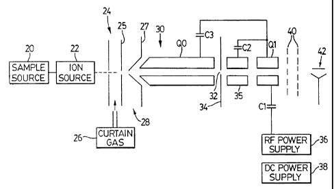
Figure 3 illustrates an apparatus in accordance with the
present invention, which may be employed to obtain a mass spectrum. A
sample source 20 (which may be a liquid or gaseous source) supplies sample
to an ion source 22 which acts as a generation means and produces ions
SUBSTITUTE SHEET (RULE 26)
. õ~
CA 02307116 2000-04-19
- WO 99123686 PGT1CA98I00999
-8-
therefrom and directs them into an interface 24 region which may be
supplied with inert curtain gas 26 as shown in US patent 4,137,750. Ions
passing through the gas curtain travel through an orifice in plate 25 to a
differentially pumped region 28, at a pressure of about 2 Torr. The ions
then pass through an orifice in a further plate 27. The interface region 24
and the differentially pumped region serve as direction means directing the
ions into a quadrupole RF-or.ly rod set QO in chamber 30, which is pumped
to a pressure of about 8 milli-Torr. Rod set QO serves to transmit the ions
onward with the removal of some gas. In addition, QO, because of the
relatively high pressure therein also serves to collisionally damp and cool
the ions to reduce their energy spread, as described in US patent 4,963,736.
From chamber 30, the ions travel through an orifice 32 in
an interface plate 34 and through a short set of RF-only rods 35 into a set of
analyzing rods Ql. The short RF-only rods 35 serve to collimate the ions
travelling into the analyzing quadrupole Ql. A conventional energy filter
40, consisting of a pair of grids, is located downstream of the analyzing rods
Ql, in the ion path, followed by a conventional detector 42.
The rods of QO may typically be about 20 cm long, the rods
35 may be typically 24 mm long, and the Q1 rods may typically be 48 mm in
length. Analyzing rods Ql are supplied with RP through capacitor Cl from
power supply 36. The same RF is supplied through capacitors C2, C3 to rods
QO and rods 35. Conventional DC offsets are also applied to the various
SU9ST{'R1TE SHEET (RULE 26)
CA 02307116 2000-04-19
-9-
rods and to the interface plates from a DC power supply 38.
The apparatus described above is otherwise relatively
conventional, and can produce a mass spectrum as the RF on the analyzing
rods is scanned.
As mentioned, ions approaching a q of 0.907 receive
additional axial kinetic energy coupled from their radial energy in the exit
fringing field at the exit of the analyzing rods Ql and are able to surmount
the potential barrier created by the energy filter and can reach the detector.
Ions with q<0.907 can also pass through the energy filter if their kinetic
energy is sufficient. These ions do not gain significant energy in the exit
fringing field and will be observed as a rather featureless background
contribution to the mass spectrum.
liL accordarLce witt't t he present IliveYition, It has now been
realized that a low level DC resolving signal applied to the rod set Ql has
numerous advantages and applied in an appropriate manner serves to
significantly eliminate unwanted background ions.
Unlike the DC signal applied to the other rod sets QO, 35,
where all the rods of each set are at the same potential, the resolving DC
signal applies the DC potential between two pairs of rods in the rod set Q1,
so that one opposite pair of rods is at one potential and the other pair of
rods is at another potential, the difference being the resolving DC potential.
Also, as detailed below, the potential is preferably scanned with mass.
Additionally, for a particular analyte, the DC potential can be selected, so
as,
to substantially eliminate unwanted background ions.
Referring to Figure 4, this provides an illustration of the
effect of gradually increasing DC voltages on a nominally RF-only mass
spectrum. The top trace 50, Figure 4a, is the mass spectrum of a mixture of
quaternary ammonium salts (0.5 picomoles/microliter each of tetramethyl
ammonium hydroxide, tetraethyl ammonium hydroxide, tetrahexyl
ammonium hydroxide, tetraoctyl ammonium bromide, and tertadecyl
ammonium bromide in 50:50 methanol water) with 0 V DC applied to the
rods Q1. This shows a broad continuum background ion signal with an
;~~51
Ati
CA 02307116 2000-04-19
WO 99t23686 PCT/CA98100999
- 9A -
onset 52 at about m/z 74. Figure 4b shows a spectrum 56 in which 7.6 V of
DC has been applied, and the onset 58 has moved to approximately m/z 280.
Referring to Pigure 4c, the lowest spectrum 60, with 15.3 V of DC shows
further movement of the onset 62 of the background to about m/z 405.
Note that there is a shift In the peak position due to the presence of the
different levels of DC. This is expetted from the stability diagram. The
effect can be eliminated simply by recalibrating the mass axis of the
irtstrumen t.
The data in Figure 4 clearly demonstrates the advantages of
low levels of DC on the continuum background intensity. The DC levels
employed here are much lower than those normaily used in conventional
RF/DC quadrupole mass spectrometry. For the RF voltage employed here,
S1/6ST'IT1JTE SttEE.T (RULE '26)
CA 02307116 2000-04-19
WO 99/23686 PCT/CA98/00999
-10-
one would normally need approximately 160 V DC at m/z 350. The data in
Figure 3 was obtained with less than 10% of the normal value.
The spectra in Figure 4 were obtained with a fixed DC
voltage and therefore a varying RF/DC ratio across the spectra. In Figure 1,
this fixed DC voltage could be represented as a horizontal line spaced above
the horizontal axis, but well below the tip or apex 14. Comparison of the
low mass peak intensities among the three spectra in Figure 4 shows that
the result is a loss of some low mass analyte intensity as the DC voltage is
increase. However the DC voltage can be readily scanned with mass over
the desired range to preserve the low mass peak intensities. An example of
this mode of operation is displayed in Figure 5 in which the DC was
scanned linearly with mass from a value of 0 V at m/z 30 to 38 V at m/z
600, so the RF/DC ratio is maintained constant throughout the scan. In
Figure 5, the spectrum is indicated at 64. This mode could be represented by
a line similar to line 12 in Figure 2, but inclined at a much smaller angle,
i.e.
with a relatively large value of Li. Figure 5 shows that this scanning mode
eliminates the problem of low mass intensity losses and produces a mass
spectrum with an excellent signal-to-noise ratio.
Although the RF/DC ratio is maintained approximately
constant in Figure 5, precise control of the ratio is not required; in
contrast
the conventional RF/DC quadrupole rod operation requires operation near
the apex of the stability boundary, and this in turn requires accurate control
on the RF/DC ratio to give the desired value of L1. Here, the DC is used
only to allow the quadrupole rods to remove high mass background
contaminating species more efficiently, prior to detection,_ rather than to
provide the means for mass spectral resolution. Thus, the value of L1 is
large and small variations in the RF/DC ratio will not significantly affect
the value of L1. It has been found experimentally that the RF/DC ratio in
the present invention can vary by more than 15% and still provide excellent
background reduction. In contrast the RF/DC ratio must be typically
maintained to better than 1% in conventional RF/DC quadrupole mass
spectrometers. Although a small amount of DC is employed in the present
invention, this does not affect filtering, and the quadrupole rods operate in
SUBSTITUTE SHEET (RULE 26)
CA 02307116 2000-04-19
WO 99a3686 PCT/CA98/00999
-11-
nominally RF-only mode and still require a downstream energy filter. The
amount of DC present does not filter by giving a small L1 /L2 ratio in Figure
1
The fact that low level resolving DC reduces the RF-only
background appears to identify the source of the background as high mass
species with sufficient kinetic energy to surmount the repulsive barrier at
the exit of the quadrupole rods. These are probably ions and ionic clusters
that have been accelerated to high kinetic energies in the atmospheric
pressure-to-vacuum interface region by the declustering voltages. Further
evidence comes from the fact that addition of modifiers to the solvent such
as acids and buffers cause this background to increase. These solvent
modifiers are known to increase the production of gas phase clusters in
electrospray ionization techniques. High declustering voltages between
orifices 25 and 27 also increase the contribution of the broad continuum ion
signal since, in this region, multiply charged ions and ionic clusters are
accelerated to proportionally higher kinetic energies than singly charged
species. It has now been found that the addition of small amounts of DC is
sufficient to render these higher mass species unstable in the quadrupole
rods, so that they fail to pass through the whole rod assembly and hence are
not detected.
The mechanism of background reduction can be further
understood with reference to Figure 6. Here the operating diagrams of an
exemplary analyte ion 97 and an exemplary background ion 98 are displayed
in term of V (RF voltage) and U (DC voltage) rather than q and a
parameters. Thus, areas under the curves 97, 98 are areas where the
respective ions would be stable and would pass through the spectrometer
for detection. If it is assumed that the higher mass species is the source of
the continuum background ion signal as is currently believed, then
operation of the RF-only quadrupole analyzer along the DC=O axis will
result in an analyte peak at an RF voltage corresponding to point 100 and a
background signal with an onset at an RF voltage corresponding to point
101 and extending to RF voltage 102. Addition of a small constant DC
voltage 99 will shift the analyte peak position to that corresponding to point
SUBSTITUTE SHEET (RULE 26)
CA 02307116 2000-04-19
- WO 99/23686 PCT/CA98/00999
-12- -
103 and the onset of the broad background to point 104. Optimization of the
DC voltage can provide complete separation between the RF voltage at
which the analyte peak appears and the RF voltage at which the continuum
background commences, so as to enhance signal-to-noise and thus to
improve analyte detectability.
It has been found that use of this technique significantly
enhances the signal-to-noise ratio of a nominally RF-only quadrupole mass
analyzer by reducing background contributions from high velocity, high
mass species that are often present.
SUBSTITUTE SHEET (RULE 26)