Note: Descriptions are shown in the official language in which they were submitted.
CA 02307160 2000-04-25
DESCRIPTION
APPLICATION METHOD FOR AT LEAST TWO DIFFERENT MEDIA AND DISPENSER THEREFOR
FIELD OF APPLICATION AND PRIOR ART
The invention relates to the application or discharge of media, particularly
pharmaceutical products in atomized, jet or drop form and a dispenser for
the same.
WO 96/24439 discloses a disposable dispenser, in which a glass ampoule
sealed by a rubber plug and containing a liquid medium is inserted in a
sleeve connected to a dispenser by means of a preset breaking connection.
The dispenser has a projecting nose adapter with an atomizing nozzle at the
end. A central shaft or member in the interior of said adapter carries in
the centre a needle which, on actuation by a manual pressing of the sleeve
into the adapter, perforates the rubber plug. The shaft then presses the
rubber plug as a plunger into the ampoule and consequently produces the
application pressure.
This disposable atomizer is very reliable and is eminently suitable for the
application of liquid medicaments, particularly those which have to be
rapidly absorbed by the body, e.g. by the nasal mucosa, whilst also avoiding
incompatibilities for the digestive tract which can arise in the case of
oral ingestion. However, there are medicaments, which are not stable for a
long period in liquid form.
Although there are numerous proposals for powder application and dosing,
this is problematical and only possible by whirling up in large air quan-
tities. This eliminates many fields of application, because a planned
application is scarcely possible in this way.
PROBLEM AND SOLUTION
The problem of the invention is to provide a method and a dispenser for the
application of two different media with which solid media can also be
applied reliably, as well as in dosed, planned manner.
CA 02307160 2000-04-25
- 2 -
medicaments, which are not stable for a long period in liquid form.
Although there are numerous proposals for powder application and dosing,
this is problematical and only possible by whirling up in large air quan-
tities. This eliminates many fields of application, because a planned
application is scarcely possible in this way.
US 3 756 390 relates to a hypodermic syringe, which has two chambers for
liquid and powder separated from one another by a piercing foil. To the
powder chamber is connected a connecting piece in which a needle can be
inserted after removing a protective cap. After piercing the separating
foil the two media are mixed together. The protective cap is then removed,
the needle inserted and injection carried out following air ejection.
A similar procedure occurs in US 3 595 439 A for a mixing cartridge for
dental two-component material.
GB 1 453 591 describes an ampoule, which has a perforatable sealing plug for
a liquid chamber and an intermediate plug for a powder chamber. On needle
perforation, e.g. connected to a drop, the intermediate plug is ejected, so
that the two media can mix with one another. The mixture can then pass
through an extra channel into the drop chamber.
JP 8-280807 A discloses an adapter, which has a liquid chamber sealed by an
aluminium foil and which can be mounted on a container with a freeze-dried
pharmaceutical. On the other side of the adapter sealed with a screw cap
can be engaged a pump atomizer, which with its suction tube perforates the
aluminium foil and thus interconnects the liquid chamber and powder con-
tainer. This dispenser which has to be assembled from three separate parts
prior to use is not very helpful for uncomplicated use purposes.
PROBLEM AND SOLUTION
The problem of the invention is to provide a method and a dispenser for the
application of two different media with which solid media can also be
applied reliably, as well as in dosed, planned manner.
Amended sheet
CA 02307160 2000-04-25
- 2a -
The invention provides a method in which a liquid is used as the carrier
medium for the particulate solid medium and the separately stored media are
only mixed together prior to their application. The term particulate solid
medium is understood to mean that it is not in the form of a gas, liquid,
paste or massive form, but instead normally dry with a certain flowability
or free-flow capability and is in particular pulverulent or granular. Thus,
it is possible to store the two media separately from one another and the
active substance can be present in dry form usually in the particulate
medium. It can e.g. be a pharmaceutical product in the form of a freeze-
dried powder. Only just prior to application is it mixed with a liquid
serving as the carrier medium. Either a suspension (dispersion) or also a
solution can be obtained, which are then jointly applied, preferably as a
spray mist, but also in drop or jet form.
Amended sheet
CA 02307160 2000-04-25
- 3 -
actions.
Advantageously between the mixing phase and the application phase there is a
pressure point which has to be manually overcome for the actuating force,
so that automatically there is a certain intermediate stop. The solid
medium will not usually completely fill the chamber in which it is stored,
which will contain an in part relatively large volume fraction of gas, e.g.
air or also an inert gas aiding product stabilization. On mixing said gas
can be compressed on introducing the liquid, so that finally on application,
i.e. the opening of the solid reservoir or a mixing chamber there is already
a certain initial pressure, which e.g. ensures a good atomization from the
outset.
In addition, a dispenser is proposed, which has a liquid chamber, pressuriz-
ing means for producing an application pressure and for delivering liquid
into a medium reservoir, separate from the liquid chamber, for a pulverulent
or free-flowing solid medium and a discharge orifice for the mixture. The
pressurizing means can be a thrust piston pump, whose cylinder can be the
liquid chamber.
Prior to the actuation of the dispenser it is possible to keep the liquid
chamber and the medium reservoir tightly sealed with respect to one another
and the outside and only to connect the same with one another and to the
discharge orifice through actuation. This can take place by perforating
membrane-like pistons or container walls, by lip valves or the like.
The building up of pressure points, which permit the build-up of certain
minimum actuating forces can take place both prior to the start of actuation
and also between the mixing and application phase, e.g. by snap connections,
but preferably by preset breaking points, i.e. material bridges which can be
destroyed by actuating forces.
In the case of dispensers, which have a separate container for each appli-
cation charge discharged all at once or in a few successive actuations, the
opening of a medium chamber usually takes place by a thin, hollow needle,
e.g. a steel needle, which is sharpened by a bevel and usually has a very
CA 02307160 2000-04-25
- 4 -
small diameter below 1 mm. It is received in a shaft, which usually also
presses the perforatable piston into the cylinder. In order to receive this
thin, sensitive needle, it has hitherto been provided with a metal adapter,
which was externally fitted to the needle as a relatively thick, solid,
metal ring. It permitted an engagement of an assembly tool and was pressed
into the shaft by means of an annular locking tooth system (cf. W0 96/24439).
This arrangement has proved satisfactory and was considered unavoidable due
to the reliable assembly without damaging the sensitive tip. However, it
requires the metal adapter as a separate part, which increases costs and
also the metal fraction in the dispenser which can otherwise be disposed of
virtually in type-pure manner.
It has now been found that it is possible to fit the very thin and sensitive
needle in damage-free manner with the necessary sealing action without said
adapter. For this purpose it is introduced between the entire central area
between the ribs of a larger bore in the shaft embracing both ends of the
needle and at the end is pressed with press fit into a bore, which is some-
what longer than the needle diameter. It is supported on a shoulder within
said bore and can consequently freely communicate to the discharge orifice.
On insertion the needle is held at its end carrying the tip by a collet,
which has a central pin engaging in the needle and consequently preventing a
crushing and damage to the sensitive tip. This is important, because
damage-free tips are necessary for the perforation of the closing plug in
the same way as in a hypodermic needle, so as to avoid the needle detaching
particles from the container or piston wall on penetrating the same and
which would lead to a clogging of the discharge orifice or could even enter
the respiratory tracts of the patient.
These and further features can be gathered from the claims, description and
drawings and the individual features, both singly or in the form of sub-
combinations, can be implemented in an embodiment of the invention and in
other fields and can represent advantageous, independently protectable con-
structions for which protection is hereby claimed. The subdivision of the
application into individual sections and the subtitles in no way restrict
the general validity of the statements made thereunder.
CA 02307160 2000-04-25
- 5 -
BRIEF DESCRIPTION OF THE DRAWINGS
An embodiment of the invention is described in greater detail hereinafter
relative to the drawings, wherein show:
Figs. 1 & 2 Longitudinal sections through a dispenser in two operating
positions.
Figs. 3 & 4 Longitudinal sections through other embodiments.
Figs. 5 to 7 Three operating positions of a further, preferred
embodiment, in each case in longitudinal section.
DESCRIPTION OF'THE PREFERRED EMBODIMENTS
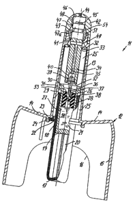
The dispenser 11 shown in figs. 1 and 2 is a disposable atomizer applying or
discharging its complete charge in a single stroke. It has a casing 12
with an elongated adapter section 13. It projects centrally out of a casing
actuating shoulder 14, which is oval in plan view and projects to two sides
in epaulette-like manner. A casing jacket 15 directed in opposition to the
adapter is connected to the shoulder 14 and has on its flatter sides in each
case an actuating cutout 16.
Through the actuating cutout 16 the actuating face 17 of a sleeve 18 is
accessible with a finger, which receives a glass ampoule 19, supported in
the sleeve by webs 20 and which contains a liquid chamber 21. The sleeve 18
and ampoule 19 are in the form of elongated, deep, circular cylindrical
containers.
Onto the plastic sleeve is shaped a ring 23 by means of thin, preset break-
ing point-forming, web-like material bridges 22 and which is received in a
snap connection 24 on the underside of the shoulder, adjacent to the inner
area 25 of the substantially hollow adapter 13.
The liquid chamber 1 in the ampoule 19 is sealed by a plug 26 made from a
rubbery material and which sealingly engages on the circular cylindrical
CA 02307160 2000-04-25
- 6 -
wall of the liquid chamber 21. It is relatively elongated and has central
recesses 28, emanating from each of its end sides and which are separated by
a central web 29, which forms a perforatable membrane. The sleeve 18 and
ampoule 19 project centrally into the inner area of the adapter 13 and are
guided there with the outer wall of the sleeve 18 and an upper flange 30 of
the ampoule 19 on lateral webs 31 in the interior 25 of the adapter 13,
namely over the length of an actuating path.
At the end of the actuating path a plunger 34 is received by means of a ring
32, which is connected thereto by means of preset breaking point-forming
material bridges 33 and which extends in the interior of the adapter 13
centrally up to just before the ampoule 19 or its plug 26. In the interior
of the plunger 34 there is a connecting channel 35, which is connected to
the inner channel 36 of a hollow ram 37, which comprises a steel needle on
which, directed towards the plug, is formed by bevelling a tip 38. The
steel needle is received in a relatively solid metal adapter ring 39, which
is externally provided with an annular, barb-like tooth system. By means of
the latter it is pressed into an opening 40 in the plunger 34 connected to
the connecting channel.
The connecting shaft 34 is guided and sealed above its predetermined break-
ing ring 32 by sealing and guiding lips 41 located in the interior 25 of
the adapter 13. By a sealingly mounted end cap 42 forming the end of the
adapter 13 an annular space is formed around the shaft 34 forming a medium
reservoir 43 for a solid medium, e.g. a powder. Centrally in the end cap
42 is provided a discharge orifice 44, which is constructed as a spraying
nozzle. It produces a conical spray jet with the aid of a vortex channel
construction 45 at the front end of the shaft 34 and in operation it
engages on the inside of the discharge nozzle 44. Spirally constructed
channels ensure an angular momentum of the liquid or mixture rapidly flowing
through them.
Between the nozzle interior and the end face of the shaft 34 is formed a
discharge chamber 46, which is sealed with respect to the medium reservoir
43 by sealing lips 47 of the end cap 42. Adjacent to the sealing lips the
discharge chamber contains in its cylindrical wall overflow channels 48.
CA 02307160 2000-04-25
- 7 -
The connecting channel 35 in the shaft 34 ends in lateral openings 49,
formed by a transverse channel, on the shaft surface.
All parts of the dispenser with the exception of the glass ampoule 19 and
the ram 37 formed by a steel needle with a metal adapter ring, are made from
plastics. The liquid chamber 21 is filled with a liquid intended to mix on
flowing out with a particulate solid medium in the medium reservoir 43, so
as to dissolve or suspend respectively disperse the same and discharge it
together with the liquid. The solid medium is a pharmaceutically active
substance, usually in powder form. The liquid mainly preponderantly com-
prises water, which is present in a sterile form and optionally in a form
physiologically adapted to the body fluid. However, also other liquids or
liquid additives are possible, which can have characteristics furthering or
initiating the activity of the solid medium. A two-component action can
arise between the liquid and the solid medium.
The dispenser according to figs. 1 and 2 is in the position shown in fig. 1
in the packing, storing and sale state. The liquid chamber 21 is filled
with the liquid 50 and tightly sealed by the plug 26. The ram 37 is just
above the web 29. The solid medium 51 is located in the medium reservoir
43, but there can simultaneously be present a normally even large quantity
of air, which is due to the gaps between the particles, but which can also
be additionally present so that the particles do not have to be filled in an
excessively compacted form. The medium reservoir 43 is tightly sealed to
the outside and inside by sealing lips 41 and 47 and the corresponding cylin-
der surfaces of the shaft 34.
For using the dispenser 11 the elongated adapter 13 is brought into the
corresponding dispensing position, e.g. inserted in a nostril. The user
grips the dispenser by placing two fingers on the shoulder 14, whilst press-
ing on the actuating face 17 with the thumb. He must initially exert a
relatively high actuating pressure in order to destroy the preset breaking
points formed by the material bridges 22 between the ring 23 and the sleeve
18 and which also form a tamper-evident closure.
The unit formed by the sleeve 18 and ampoule 19 is then moved upwards, i.e.
CA 02307160 2000-04-25
- 8 -
into the interior 25 of the adapter 13. The needle-like ram 37 perforates
the web 29 in the closing plug 26 and the lower face 52 of the shaft 34,
which has a somewhat smaller diameter than the liquid chamber 21, strikes
the face 53 of the plug 26. The latter consequently forms the piston of a
thrust piston pump, whose cylinder is formed by the liquid chamber 21 or
glass ampoule 19.
The upwardly directed axial pressure acting on the shaft 34, on actuation,
also breaks the material bridges 33 connecting the ring 32 to the shaft 34,
so that the shaft 34 is moved upwards in fig. 2 until its upper face engages
with the vortex channel construction 45 on the upper end wall bounding the
discharge chamber. As can be seen in fig. 2, in this position the connect-
ing channel 35 is connected by means of the lateral openings 49 to the
annular medium reservoir 43, but which remains sealed by the lips 41 to the
adapter interior 25. However, the upper sealing lip 47 is bypassed by an
annular groove 54 in the shaft, so that a discharge flow channel is formed
via the overflow channels 48 and the vortex channel construction 45 to the
discharge orifice (nozzle) 44.
The pressure of the shaft 34 on the plug/piston 26 produces the necessary
application pressure, which delivers the liquid through the needle 37, the
connecting channel 35 and the openings 49 into the medium reservoir 53,
where it is mixed with the solid medium 51, which can be aided by the design
of the medium reservoir and/or the openings 49, e.g. through their inclined
position for the production of a vortex. The resulting mixture is then dis-
charged from the discharge orifice, particularly in finely sprayed form.
The sealing lips 47 together with the upper piston section 47a or the groove
54 form the discharge valve. The dispenser is intended with a single, but
in this case two-stage actuating stroke to discharge the complete solid
medium and liquid charge stored in it in separate and tightly sealed form.
Apart from the differences described hereinafter, the construction of the
dispenser according to fig. 3 is the same as that shown in figs. 1 and 2.
Reference is made to the description of the latter and the same reference
numerals are used.
CA 02307160 2000-04-25
- 9 -
In the sleeve 18 is received an ampoule 19, which is longer than that
according to fig. 1. In axially succession it contains both the liquid
chamber 21 and also the medium reservoir 43a. Thus, apart from the closing
plunger 26 sealing the medium reservoir 43a here, the ampoule 19 contains an
intermediate piston 55 separating the liquid chamber 21 from the medium
reservoir 43a and which in the rest state shown in fig. 3 seals the two
chambers from one another. For the connection thereof a connecting channel
35a is formed in the wall of the ampoule 19 and its outlet into the medium
reservoir 43a is sealed in the rest state of the intermediate piston 55.
The shaft 34 is sealingly inserted in a support section 56 of the adapter
13, which is constructed in one piece with the casing 12 (and therefore
with the adapter 13). The hemispherical adapter end 57 is also constructed
in one piece therewith in that also the nozzle-like discharge orifice 44 is
provided. On its upper end face the shaft contains the vortex chamber
construction 45 cooperating with the discharge nozzle. The shaft receives
the ram 37, which is formed by a steel needle and extends almost entirely
through the shaft 34 up to just before its upper face. The needle, which
generally has an external diameter of less than 1 millimetre and a corres-
pondingly small wall thickness, is very carefully sharpened for forming a
sharp, burr-free tip 38 and without the adapter 39 shown in fig. 1 is
directly inserted in a bore 58 of the shaft. This bore has a much larger
diameter than the needle 37, but guides the latter through e.g. four webs
59 projecting radially inwards from the bore inner wall and which commence
with an insertion bevel 60 in the vicinity of the face 52 of the shaft 34.
They ensure a precise centring and prevent buckling of the thin needle on
insertion. They extend from the free end of the shaft up to a fitting bore
61, i.e. over most of the central area of the needle particularly important
for preventing buckling.
At the upper end, i.e. that remote from the tip 28, the needle 37 is pressed
into a fitting bore 61, which is so dimensioned that it permits a tight
press fit of the needle therein. A shoulder 62 in said fitting bore forms
an upper stop for the pressing in of the needle. The fitting bore embraces
the upper end of the needle over a length greater than a multiple, e.g.
five times the external diameter of the needle. The upper end of the
CA 02307160 2000-04-25
- 10 -
fitting bore is connected to the discharge chamber 46.
The dispenser comprises very few parts. The shaft 34 with the needle fitted
therein is inserted in the one-piece casing, in which is directly shaped the
discharge orifice 44. The dispenser is completed by the sleeve 18/ampoule
19 unit with closing plug 26 and the intermediate piston 55, separating the
liquid and the medium chamber.
The assembly of the dispenser in accordance with fig. 3 is very simple. As
a result of the novel construction of the shaft 34 the needle can be fitted
without the annular adapter 39 in accordance with fig. 1. The ribs 59 guide
the needle on entering the bore 58, without opposing an excessive resistance
in the longitudinal direction. Only when the needle has been guided over
most of its length between the ribs does it enter the fitting bore 61, where
it is pressed in in a sealing manner so as to be secured mechanically
against extraction. As can be gathered from the drawing, only over a rela-
tively small part of its length, usually less than one third, does the
needle project from the shaft 34. Thus, the section most endangered by
buckling, which is in the centre of the needle, when force is applied for
its pressing into the fitting bore 61, is already guided in buckling-
preventing manner between the ribs.
It is particularly important that the sensitive needle tip 28 is not damaged
during the pressing in process. Therefore working takes place with a tool,
which grips the needle from the outside with a type of collet (in the area
projecting from the shaft), but which additionally has a central pin engaging
in the needle bore and consequently protecting the needle against crushing
and damage to the tip.
The prefitted shaft can then be pressed into the connecting piece 56 with
its upper, partly bevelled offset end.
The prefitted unit constituted by the sleeve and inserted ampoule 19 is
fitted by means of the snap closure 24 to the casing 12. Beforehand the
ampoule was filled with the liquid, followed by the fitting of the inter-
mediate piston 55 and then the filling of the solid medium into the medium
CA 02307160 2000-04-25
- 11 -
reservoir 43 above it. The closing plug 26 was then fitted.
As in figs. 1 and 2, on actuation the preset breaking point 22 is destroyed
for obtaining an adequate initial pressure, which ensures that the user
continues to the end the actuation with a certain force and speed. An
interim interruption would e.g. lead to the dripping of the atomizer and
would optionally impair the mixing of the substances or prevent a complete
application.
Then the ram 37 (needle) perforates the web 29 in the piston 26 and then
opens the discharge channel 36, mainly formed by the interior of the hollow
needle 37, with respect to the medium reservoir 43a. The shaft 34 presses
the piston 26 downwards and compresses the solid medium 51 in the medium
reservoir 43a, together with the air (or a corresponding inert gas) con-
tained therein: Thus, the intermediate piston 55 is also pushed downwards
and frees the connecting channel 35a in the ampoule wall. The latter could
also be formed by a corresponding protuberance of said wall, which would
then free an overflow channel on its two sides. The liquid 50 flows out of
the liquid chamber 21 into the medium reservoir 43a, where it mixes with the
medium 51 and is passed with the corresponding discharge pressure via the
needle bore 36 to the discharge orifice 44. The sleeve 18/ampoule 19 unit,
guided by the webs 31, slides upwards in the interior 25 of the nose adapter
13. Here again a complete discharge of the two media (plus the third
medium "air") is possible. The air also forms a precompression, which aids
the start of the atomizing phase. Optionally the arrangement could also be
such that the medium was placed in the bottom-near area of the ampoule and
the liquid above it. In this case the liquid would firstly flow downwards,
mix there with the medium and then flow through the liquid chamber to the
outlet. This could optionally bring about a particularly intimate mixing.
Fig. 4 shows a particularly simply constructed embodiment. In an ampoule
19, which can also be made from plastic and is in the form of a particularly
deep bowl, is guided a liquid piston 64 sealing with piston lips and which
is constructed in one piece at the lower end of a piston rod 65. A connect-
ing chamber 63 receives the ball on being pressed out and a vortex channel/
nozzle arrangement 80 similar to the nozzle 44 with vortex channel 45
CA 02307160 2000-04-25
- 12 -
ensures a jet distribution aiding the mixing of the media, optionally accom-
panied by angular momentum and atomization in the medium reservoir 43b.
It has a through central bore 66, in whose upper section is pressed a ball
67 as the sealing valve. Over the end of the piston rod 65 is engaged a
sleeve-like adapter cap 13b, so that between the upper face 68 of the piston
rod 65 and the interior 69 of the adapter cap 13b is formed the medium
reservoir 43c. A discharge orifice 44 formed at the end of the adapter cap
can be constructed as a spray or drop nozzle. It is sealed by a pull-off
closure 70, e.g. a sealed-on aluminium foil.
The adapter cap 13b has lateral actuating shoulders 14b and engages with its
lower part in the interior of the ampoule 19, i.e. it is guided on the
cylinder wall 27. Resilient tabs 71 disengaged from the wall of the adapter
cap 13b form together with a groove in the cylinder wall 27 on the one hand
a snap closure securing the rest state and preventing a pulling of the
adapter cap 13c from the ampoule and on the other ensure the necessary
actuating force build-up prior to the start of actuation. As a result of
the barb-like construction pulling off can be prevented and the actuating
force build-up can be dimensioned in a predetermined manner.
This dispenser comprises a few relatively simple plastic parts, a foil por-
tion and a small steel or plastic ball. It could also be replaced by a
perforatable membrane or a membrane tearing through liquid pressure.
On production the liquid chamber 21 is filled with liquid 50, the piston/
piston rod unit 64, 65 is inserted and then the adapter cap 13b, filled with
the medium 51, is inserted.
For using the dispenser according to fig. 4 firstly the pull-off closure 70
is pulled off, so that the discharge orifice 44 is open. Then, accompanied
by the overcoming of the pressure point produced by the spring tabs 71, the
piston 64 is pressed into the sleeve 19 (or vice versa). The resulting
liquid pressure forces the ball 67 out of the overflow channel 66 into the
chamber 63. The liquid sprays with an angular momentum in a sharp jet or
atomizes in the medium reservoir 43b, mixes there with the medium 51 and
CA 02307160 2000-04-25
- 13 -
passes as a mixture out of the discharge orifice 44.
Here again, prior to actuation, the individual chambers must be completely
sealed with respect to one another and to the outside. The pull-off closure
70 could also be replaced by a valve opening in pressure-dependent manner,
but is generally unnecessary in the case of a disposal dispenser. In this
or the following construction according to figs. 5 to 7 it is also possible
to use a discharge valve, which is deliberately opened by the user only
following a mixing phase, e.g. a rotary slide valve, which is operated by
rotating the upper section of the adapter cap 13, 13b with respect to the
remaining casing. As a result of the rotation it would also be possible to
free a stop, which prevented the piston rod during the first actuating step
(mixing) from immediately discharging the mixture. The time required for
operating the rotary valve could e.g. ensure the dissolving of the powder
in the liquid.
In connection with the embodiments according to figs. 5 to 7 reference is
again made to the detailed description of figs. 1 to 3 and only differences
are described hereinafter.
The main difference is the unit containing the media and comprising the
sleeve 18 and the ampoule 19. The sleeve 18, which is fitted to the casing
12 by means of the preset breaking ring 32, contains the liquid chamber 21
in its lower area facing its bottom 17, where a plastic ram 37c is formed,
which projects centrally upwards in the sleeve and has a cruciform cross-
section.
In piston-like sealing manner an inner sleeve 19c is inserted in the sleeve
and has on its bottom a perforatable membrane 29c. This sleeve seals in the
upward direction the liquid chamber. It is inserted by means of a preset
breaking ring 32 into the interior 25 of the nose adapter 13. The preset
breaking ring operates with material bridges 33, as described hereinbefore.
The inner sleeve 19c forms a cylinder for a reservoir/mixing chamber 43c,
which is upwardly sealed by an inverted, sleeve-shaped closing plug 26c
serving as a piston.
CA 02307160 2000-04-25
- 14 -
During the manufacture of the dispenser 11 according to figs. 5 to 7 the
liquid 50 is introduced into the liquid chamber 21 and the solid medium 50
into the medium reservoir 43c, which is sealed by the closing plug 26c. The
inner sleeve 19c is inserted in the manner of a piston into the sleeve 18,
which consequently forms the cylinder of a second thrust piston pump on said
dispenser and upwardly seals the liquid chamber 21.
On actuation firstly the preset breaking closure 32 is broken through. The
ram 37c then penetrates through the membrane 29d and by means of the chan-
nels formed in the cruciform cross-section forms the connection between the
liquid chamber 21 and the medium reservoir 43d. The piston-like, lower part
of the inner sleeve 19c reducing the size of the liquid chamber 21 feeds
the liquid 50 into the medium storage space 43c, which thereby increases in
size, in that under the thus formed medium pressure it forces upwards the
plug 26c.
Fig. 6 shows the end of this mixing phase in which the liquid and solid
medium are mixed. It is ended in that, as shown in fig. 6, the bottom of
the inner sleeve 19c engages on the bottom 17 of the sleeve 18. There is
then only a common mixing chamber 43c. The air previously present in the
medium chamber 43c can compress to a greater or lesser extent as a function
of the resistance of the plug 26c and consequently maintain a basic pressure
in the mixing chamber.
The preset breaking closure 32 can be set in such a way that the user, on
reaching the position shown in fig. 6, must apply a further, increased pres-
sure, which ensures that there is an adequate time in the mixing chamber 43c
for mixing and optionally dissolving the constituents.
As shown in fig. 7, the preset breaking closure 32 then breaks, the needle
37 penetrates through the bottom 29d of the closing plug 26c, which is then
contacted by the face 52 of the shaft 34 and is pressed in the manner of a
piston into the inner sleeve 19c forming a pump cylinder. The mixture 50/51
is then transported from the mixing chamber 43d via the discharge channel
formed by the needle bore 36 to the discharge orifice 44 and is atomized
there under the discharge pressure or is discharged in some other way. As
CA 02307160 2000-04-25
- 15 -
described relative to fig. 3, the application phase could be time-limited in
addition to or in place of the preset breaking ring 32 by a stop released by
rotation. It is also possible to use in place of the perforating needle a
rotary slide valve which is opened by this rotation.
Thus, in this embodiment the mixing phase can be spatially and also time
separated from the application phase, although everything substantially
directly successively takes place, i.e. there is no risk of the solid medium
being damaged in the mixing phase. It is also possible to distribute these
two phases over two different actuating strokes instead of carrying them
out in two axially succeeding stroke sections, as in figs. 5 to 7. By a
corresponding subdivision or sequence of strokes, it is also possible to
discharge a charge premixed in a first stroke in two succeeding partial
discharge strokes, in order e.g. to successively apply a medicament to the
two nostrils of a patient. A multiple use dispenser or rechargeable dis-
penser in accordance with the above-described principle is also possible.